Load Analysis and Power Calculation for 4 Roll Bending
Ever wondered how massive metal sheets transform into precise cylindrical shapes? This article unveils the fascinating mechanics behind four-roll plate bending machines, exploring their structure, working principles, and the critical calculations for motor power selection. Get ready to dive into the engineering marvels that power industries like shipbuilding and petroleum!
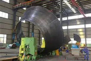
A plate rolling machine is a universal forming equipment that rolls sheet metal into cylindrical, arc, and other general shapes.
It is widely used in industries such as boilers, shipbuilding, petroleum, chemicals, metal structures, and mechanical manufacturing.
The four-roll plate bending machine is known for its convenient center alignment, small amount of straight edge surplus, high accuracy in roundness correction, and efficiency, as it can complete pre-bending and workpiece forming in a single rolling process without the need to switch the plate end.
It is becoming increasingly important in sheet metal forming.
The roll bending force conditions during the operation of the four-roller plate bending machine are complex and involve a significant load, requiring strong and rigid bearing parts.
Thus, precise and reliable design of the plate rolls is essential.
To begin, the force parameters of the roll bending machine need to be determined, such as the pressure on the roller, bending torque, and motor-driven power.
The load analysis of the rolling machine can serve as reference data for designing the plate rolls.
The calculation of the main driven power of the plate roll bending machine is crucial in choosing the main motor.
The motor power must be selected carefully, as a motor that is too small will be overloaded for long periods and damaged due to heat from insulation, while a motor that is too large will not fully utilize its output power and waste electricity.
Therefore, conducting a load analysis and improving the driven power calculation of the four-roll plate bending machine has practical value in choosing a suitable motor.
In this post, we not only introduce the basic structure and working principle of the four-roll plate bending machine, but also analyze its force capabilities, and provide the calculation formula for the main driven power of the four-roll bending machine.
Four Roll Bending Machine Structure and Working Principle
The rolling machine operates based on the principle of three-point forming, utilizing the relative position change and rotational motion of the working roll to produce continuous elastoplastic bending and achieve the desired shape and precision of the workpiece.
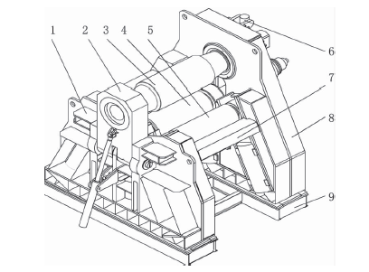
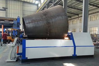
The structure of the four-roller plate bending machine is shown in Figure 1 and is composed of several parts including a low frame, overturn device, upper roller, lower roller, two side rollers, high frame, connecting beam, base, balancing device, transmission device, electrical system, and hydraulic system.
The working roll of the four-roller plate machine consists of four rolls: an upper roll, lower roll, and two side rolls.
The upper roll is the main drive roll and is embedded in the high and low frame through a bearing body. Its position is fixed, allowing only for rotational motion.
The lower roll is fixed in a bearing pedestal, which can move in a straight line to compensate for the thickness of the bent plate.
The two side rollers are also installed in bearing pedestals, which can move up and down at a certain angle with the vertical direction to achieve the desired radius of cylinder curvature.
Fig.1 Structure of four-roll plate bending machine
1. left frame
2. overturn the device
3. upper roller
4. lower roller
5. side roller
6. balancing device
7. connecting beam
8. right frame
9. base
In general, rolling a metal sheet into a cylindrical workpiece on a four-roll bending machine consists of four processes, namely:
During the operation of the rolling machine, the front end of the plate is placed between the upper and lower rollers and aligned with one of the side rollers. The lower roller is then raised to tightly press the plate, and the other side roller is lifted to apply force and bend the end of the metal plate.
For pre-bending the other end of the plate, it does not need to be removed from the rolling machine. Simply move the plate to the other end of the machine and repeat the process.
Continuous rolling is achieved through one-time or multiple-time feeding until the desired cylinder curvature radius is reached.
Finally, roundness corrections are performed to achieve the required roundness and cylindricity.
It can be seen that using the four-roll plate bending machine allows for the plate to be placed into the machine only once, achieving all the required bending.
Load Analysis
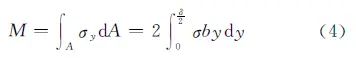
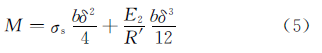
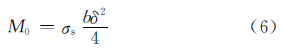
2.1 Calculation of the maximum bending moment of the plate
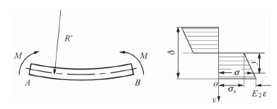
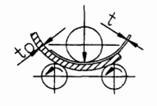
As shown in FIG. 2, the stress distribution of the plate section along the direction of steel plate height during the linear pure plastic bending is shown in FIG. 2.
Fig.2 Stress distribution of plate
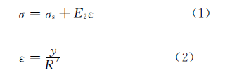
The functional relation of true stress can be expressed as follows:
In the above formula:
σ – the stress of the workpiece;
σs– the yield limit of the material;
ε – the strain of the workpiece;
ε – The linear reinforcement modulus of the material, can be found on the relevant manual.
y- The distance from the neutral axis to any point;
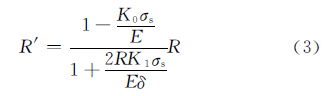
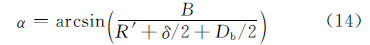
R′ – The radius of curvature before the neutral layer rebound, can be calculated as follows:
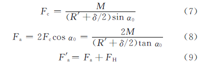
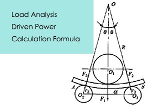
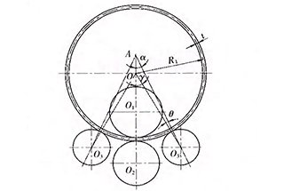
α0 – The angle between the force action line of the side roller and the force line of the upper roller.
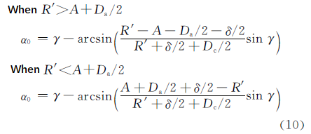
The value of α0 can be determined by the following formula according to the geometric relationship:
In the above formula:
Da – Upper roll diameter;
Dc – Side roll diameter;
γ – Tilt Angle of the side roll, which is the angle between the adjustment direction of the side roller and the vertical direction;
A – The distance from the intersection point of the roll angle to the center of the upper roller.
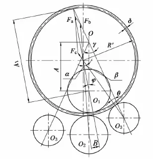
2.2.2 The rollers are arranged in an asymmetrical manner
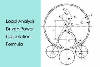
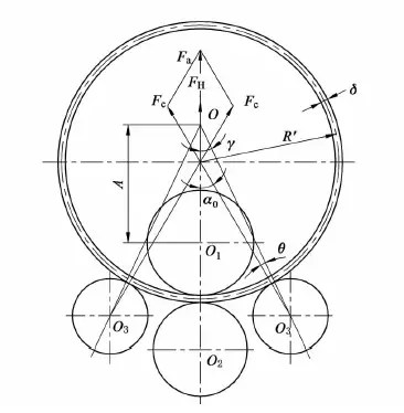
The force of the steel plate is shown in FIG. 4 when the roller is arranged asymmetrically.
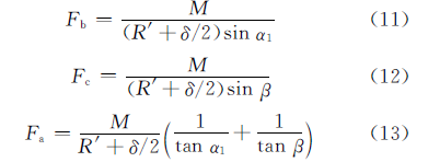
According to the force balance, the force of each working roll on the steel plate can be obtained:
In the above formula:
Fb– Lower roll force;
α – The angle between the force action line of the upper roller and the force line of the lower roller;
β – The angle between the force action line of the upper roller and the force line of the side roller.
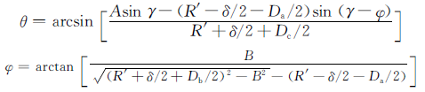
The value of α, β can be determined by the following formula according to the geometric relationship:
In the above formula:
Db – Lower roll diameter;
B – The distance between the action line of the upper roller and the center of the lower roller,
B= [1+Db /(2R’+δ]B’;
B’ – The length of the remaining straight edge, B’=2δ
In the formula: A1 = Asinγ/sin(γ – φ)
Driven Power Calculation
3.1 Upper roller drive torque
The upper roller of the four-roll bending machine is a driven roller, and the total drive torque acting on it is the sum of the torque consumed by deformation and friction.
The friction torque includes the friction resistance consumed in rolling the shaft roller on the bending plate and the torque consumed by bearing friction.
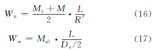
The torque consumed in deformation can be determined by the work done by the internal bending force and the external force on the upper roller.
In the formula:
Wn – The work done by bending internal forces;
Ww – The work on the upper roller by external forces;
L – The bending Angle corresponds to the length of the plate.
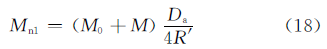
Make formula (17) equal to formula (18), we get the torque consumed in deforming:
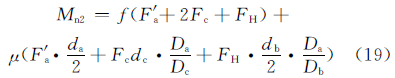
The torque for overcoming friction can be determined by formulas (19) and (20).
Friction torque of shaft roller in the symmetrical arrangement:
Friction torque of shaft roller in the asymmetrical arrangement:
In the above formula:
f – Coefficient of rolling friction, f =0.8mm
μ – Sliding friction coefficient of the roller neck, μ=0.05-0.1;
da, db, dc are the roller neck diameter of the upper roller, lower roller and side roller separately.
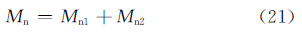
The total driving torque on the upper roller is:
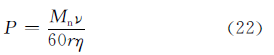
3.2 Upper roller drive power
The calculation formula for driving power is:
In the formula:
ν – Rolling speed;
r – Driven roller radius, r=Da /2
η – Transmission efficiency, η=0.9
According to the actual application condition of the four-roll plate bending machine, the driving power of the driving roller is calculated during the pre-bending and rolling process, and the driving power of the main drive system is the larger value in the calculation result:
In the above formula:
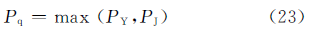
Pq – Driving power of the main drive system;
PY – The driving power of the driving roller when pre-bending;
PJ – The driving power of the driving roller when rolling circle.
The calculated value Pq of the driving power can be used as the basis for selecting the main motor power.
Conclusion
(1) Based on the structural characteristics and working principle of the four-roll plate bending machine, the force of the working roller is analyzed and the formula for calculating the working roll under different arrangements is obtained.
(2) By analyzing the maximum deformation bending moment and bearing force of the working roller, and using function transformation principles, the relationship between force, bending moment, and device driving power is established. A method to calculate the driving power of the main drive system is proposed.
According to actual application conditions, the driving power for pre-bending and rolling is calculated separately, and the main motor power is selected based on the larger calculated value.
As the founder of MachineMFG, I have dedicated over a decade of my career to the metalworking industry. My extensive experience has allowed me to become an expert in the fields of sheet metal fabrication, machining, mechanical engineering, and machine tools for metals. I am constantly thinking, reading, and writing about these subjects, constantly striving to stay at the forefront of my field. Let my knowledge and expertise be an asset to your business.
Imagine trying to bend a thick steel plate into a perfect cylinder—how much force would you need? This article dives into the critical calculations for determining the load and power…
Have you ever wondered how those massive steel structures are formed into perfect curves? Roll bending is the secret behind it. In this article, we'll dive into the fascinating world…
Have you ever wondered how complex shapes like cones and cylinders are crafted from flat metal sheets? This article explores the fascinating process of roll bending, breaking down the steps…
Have you ever wondered how massive steel structures are shaped into perfect cylinders and cones? This article explores the fascinating world of plate rolling machines, essential tools in industries like…
Have you ever wondered how a four-roller plate bending machine achieves such precise curves? This article explores the calculation of side roll position shifts, guided by an experienced mechanical engineer.…