Plate Roll Bending Calculations: Conversion Formula
Have you ever wondered how those massive steel structures are formed into perfect curves? Roll bending is the secret behind it. In this article, we'll dive into the fascinating world…
Have you ever wondered how a four-roller plate bending machine achieves such precise curves? This article explores the calculation of side roll position shifts, guided by an experienced mechanical engineer. Discover the key principles and techniques that make this machinery marvel possible.
According to the principle of three-point rounding, the plate bending machine utilizes the rotary motion and relative position change of the work roll to achieve continuous elastic-plastic bending. This results in metal sheets being bent into predetermined shapes such as cylinders and arcs, as well as precision workpieces.
The plate bending machine is widely used in various industries, including boiler manufacturing, shipbuilding, petrochemicals, metal structure, and sheet metal forming machinery.
Based on the number of rolls, the plate bending machine can be classified into two-roll, three-roll, and four-roll types, each with its unique characteristics.
In comparison to the traditional two-roll type, the four-roll plate bending machine has several advantages, including easier centering, a smaller residual straight edge, higher precision in circle straightening, and improved production efficiency.
In addition, the four-roll plate bending machine is capable of performing plate end preplex and workpiece rolling without the need for turning, making it increasingly important in sheet metal forming.
The machine is composed of an upper roll, a lower roll, and two side rolls at the front and rear. The upper roll rotates at a fixed position while the steel plate is fed through friction. The clamping, preplex, and rolling process of the steel plate are controlled by adjusting the position of the lower roll and the two side rolls.
To enhance the rolling accuracy of the steel plate, it is crucial to study the accurate positions of the lower roll and the two side rolls. Currently, the position control of these components is determined by the operator through repeated adjustments based on experience, and the rolling accuracy is monitored through continuous comparison and model checking, resulting in low accuracy and efficiency.
This article proposes a calculation formula for the springback curvature radius based on the elastic recovery theory, and studies the position requirements of the lower roll and two side rolls in the process of rolling steel plate. A mathematical model for calculating the positions of these components during aligning, preplex, and bending is established.
The study accurately determines the displacement of the lower roll and the front and rear side rolls during the rolling of the steel plate, providing accurate feed data for digital control. The results of this method, as verified through production practice, show consistency with practical applications, leading to improved rolling accuracy and efficiency.
The four-roll plate bending machine is composed of several key components, including the upper roll device, lower roll device, side roll device, overturning device, low rack, base, high rack, and hydraulic pump station.
The upper roll serves as the driving roll and is rotated by a servo motor through a transmission device, with its position being fixed. The lower roll and side roll are driven rolls, whose rotation is powered by friction with the steel plate.
The lower roll is fixed in its bearing seat, which can move vertically in a sliding guide groove on the frame to accommodate different plate thicknesses. The side rolls are installed in side roll bearing seats.
In order to form the desired curvature radius of the cylinder, the side roll bearing seat moves up and down in an inclined direction within the sliding guide groove, with a certain angle relative to the vertical direction.
The overturning and reset of the lower roll, side roll, and upper roll are controlled by a hydraulic cylinder. The overall structure of the equipment is depicted in Figure 1.
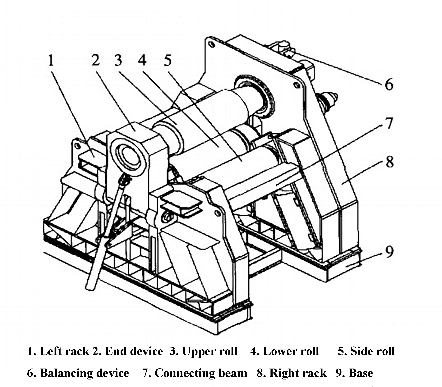
Fig. 1 Structure of four-roll plate bending machine
The process of rolling steel plate typically consists of six steps, including preparation, feeding, prebending, prebending on the other side, rolling forming, and arc correction. This process is depicted in Figure 2.

Fig. 2 Technological process of four-roll plate bending machine
1.2.1 Preparation and feeding
The lower roll is lifted to a position where the distance between the upper generating line and the lower generating line of the upper roll is slightly greater than the thickness of the workpiece.
The rear side roll is lifted to a position where the upper generatrix and the upper generatrix of the lower roll are in the same horizontal plane, and then the front side roll is lifted to a position where its center line is located between the upper and lower rolls (as shown in Figure 2a).
The workpiece is fed horizontally between the upper and lower rolls, with the front end pressing against the front roll. The lower roll is then raised to clamp the steel plate (as shown in Figure 2b).
With these steps completed, the preparation and feeding process is finished.
1.2.2 Prebending
The front side roll is returned to its original position and the rear side roll is raised to the process height for the prebending curvature of the steel plate (as shown in Figure 2c).
The upper roll rotates counterclockwise to drive the steel plate forward. When the end of the steel plate reaches half the distance between the two rollers, it should be measured to ensure it reaches the required curvature.
The process for prebending the other end is similar to what has been described above.
1.2.3 Roll bending
The front side roll is raised to the process height for the required curvature, while the rear side roll is lowered so that both front and rear side rolls are at the same level.
The upper roll rotates counterclockwise to drive the movement of the steel plate forward, causing it to curl. At the same time, the curvature of the protruding steel plate is measured using a template, and the process height is adjusted as necessary to achieve the desired radian (as shown in Figure 2d).
The arc correction process is similar to the roll bending process.
Currently, the majority of coils are produced through cold rolling. The springback phenomenon is quite pronounced in this process, so an adequate amount of overwinding is required to compensate for it.
Typically, the springback radius should be less than the desired radius of the parts (pre-bending radius).
Based on elastic-plastic mechanics, the springback in sheet metal processing is influenced by factors such as the elastic modulus, strengthened elastic modulus, yield limit, pre-coiling radius, and sheet thickness.
Through theoretical derivation, the calculation formula for the radius of curvature before recovery can be determined as follows:

In the formula:
The analysis of the steel plate rolling process reveals that the position of the upper roll remains unchanged during rolling and that the rolling is mainly accomplished through the vertical movement of the lower roll and the angled feed of the two side rolls.
Therefore, the accurate rolling of the steel plate can be achieved by precisely controlling the position of each roller during the process.
The following focuses on the mathematical modeling and calculation of the process positions of the lower roll and side rolls during the key processes such as forward movement, prebending, and coiling.
The calculation takes into account factors such as the rolling machine’s geometric parameters, the material and thickness of the rolled steel plate, and the rolling radius.
The following symbols are typically used to derive the displacement formula for the back roll and both sides of the plate bending machine:
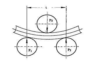
During the alignment process of the plate bending machine, as depicted in Figure 2, the lower roll and both side rolls undergo corresponding displacement. The process position of each roller during alignment is depicted in Figure 3.

Fig. 3 Process position of aligning rolls
The displacement of the two side rolls and the lower roll can be calculated based on the geometric relationship, as follows:

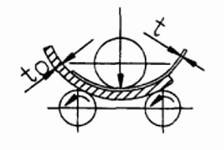
During the prebending process of the bending machine, as shown in Figure 2, the lower roll and front and rear rolls undergo corresponding displacement.
To meet the requirements of the prebending process, the process position of each roll during left prebending is shown in Figure 4. During right prebending, the positions of the front and rear rolls are simply swapped, while the position of the lower roll remains unchanged.
The value of the geometric parameter B can be calculated using the calculation formula for the asymmetric three-roll plate bending machine. In this article, B is taken to be equal to 2t.

Fig. 4 Process position of each roll during prebending
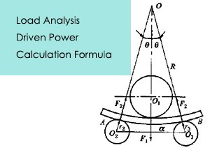
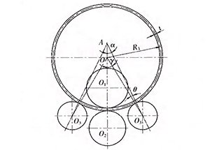
Suppose “O” is the center of curvature prior to springback, “y” represents the angle between the upper roll center and the bending center line “OO1” and the angle between the lower roll center and the bending center line “OO2.”
The angle “φ” represents the angle between the line “O1O2” between the upper roll center and the lower roll center, and the line between the upper roll center and the bending center.
The angle “θ” represents the angle between the line “AO3” between the center of the bending machine and the center of the side roll, and the line “OO3” between the center of the side roll and the bending center.
Based on these geometric relationships, the following conclusion can be drawn:
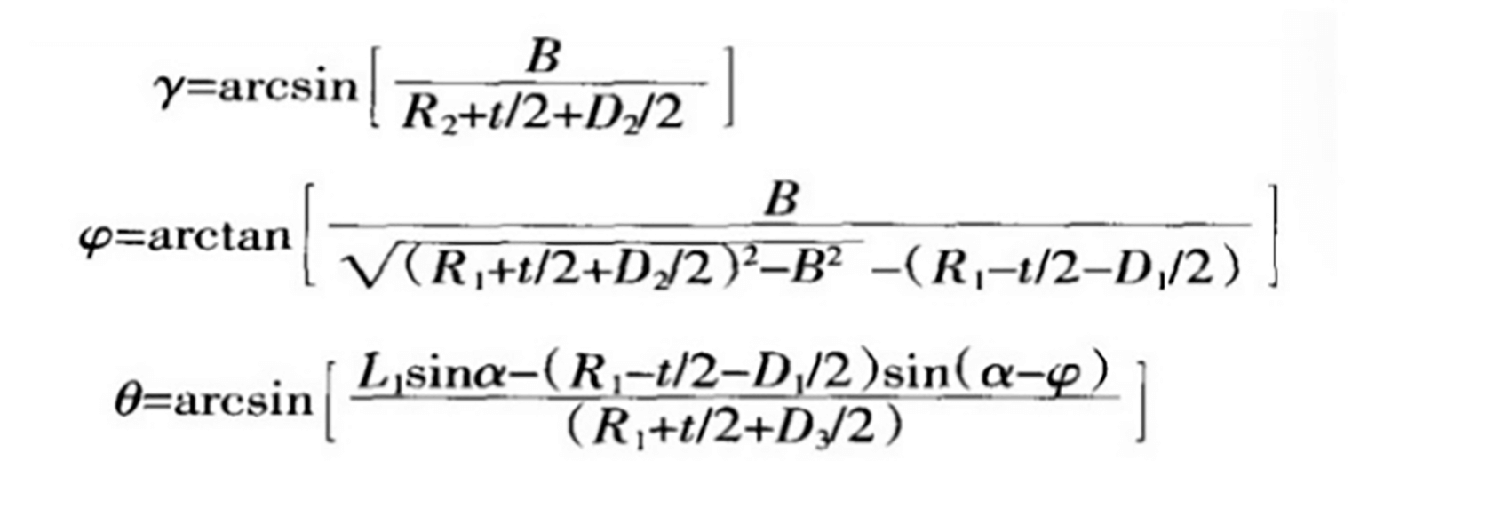
In the formula, the geometric parameter B is the value from the center of lower roll O2 to OO1, which can be calculated according to the formula of the asymmetric three-roll plate bending machine.
In this article, B = 2t, and other parameters are the same as the above.
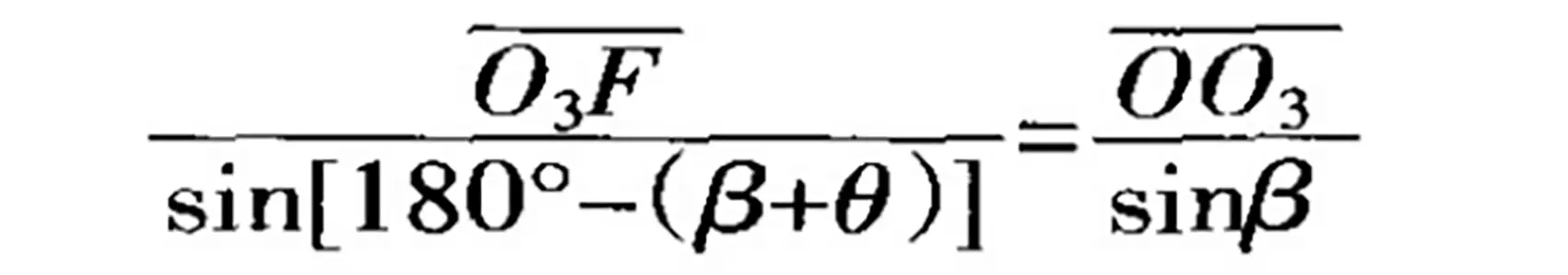
Suppose that F is the intersection of OO2 and AO3, and β is the angle between F and the middle line of upper and lower rolls.

In △ AFO2, according to the sine theorem:

Thus:

Similarly, in △ AFO2:

Thus:

In △ AFO2:
Thus:

That is:

Therefore, the displacement between the two side rolls and the lower roll is:
When the right side is prebending, Y1 remains unchanged, Y2 and Y3 can be interchanged.
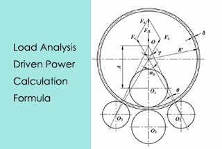
In the continuous bending process of the plate bending machine depicted in Figure 2, the two side rolls are positioned symmetrically, and the lower roll and the front and rear side rolls have corresponding displacements.
To meet the requirements of the continuous bending process, the position of each roller during the process is displayed in Figure 5.

Fig. 5 Process position of each roll during continuous bending
According to the geometric relation, in △OAO3, from the sine theorem:

Thus:

Suppose that O is the center of curvature before springback, λ is the angle between OO2 and OO3, then:

In △OAO3:

Thus:

If Y1 remains unchanged, Y2=Y3=L3-AO3, so the displacement of the rollers on both sides and the lower roller is:

An experimental study was conducted using a W1220 x 2500 plate rolling machine, with a 10 mm thick plate made of Q235 material and a rolling radius of 700 mm.
The results of the experiment showed that there was an absolute error of 4.8mm between the actual circle radius and the required circle radius, resulting in a relative error of 0.68%. Based on these results, it was determined that the correction was sufficient to meet the accuracy requirements.
Upon analyzing the test data from multiple attempts to adjust the springback radius, it was found that the primary cause of error was the assumption that the plate was undergoing pure bending during the calculation of the springback radius, and not taking into account the impact of extrusion force and friction.
However, the technical analysis showed that the displacement calculation was accurate and met the requirements of the process.
This article presents an analysis of the rolling process of a four-roll plate rolling machine. By combining the calculation formula for the springback radius with mathematical and mechanical methods, the article analyzes the position of each roller during the machine’s working process.
The results of the calculation were tested on a four-roll plate bending machine.
The results of the experiment showed that this method can significantly reduce the number of tests and improve the accuracy and efficiency of the rolling process.

As the founder of MachineMFG, I have dedicated over a decade of my career to the metalworking industry. My extensive experience has allowed me to become an expert in the fields of sheet metal fabrication, machining, mechanical engineering, and machine tools for metals. I am constantly thinking, reading, and writing about these subjects, constantly striving to stay at the forefront of my field. Let my knowledge and expertise be an asset to your business.