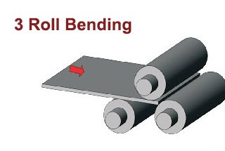
Have you ever wondered how massive steel plates are transformed into perfectly curved shapes? In this captivating blog post, we’ll dive into the fascinating world of 3-roll bending machines. Discover the ingenious working principles behind these mechanical marvels and gain insights from industry experts. Whether you’re an engineering enthusiast or simply curious about manufacturing processes, this article will unveil the secrets of precision metal bending. Get ready to be amazed by the power and precision of 3-roll bending machines!
With the rapid development of manufacturing, driven by the national clean energy policy, the demand for coal-fired, hydropower, nuclear power, and wind power has increased, along with the need for large plate rolling machines to process pipeline and column tower parts.
The offshore oil and gas, petrochemical, coal chemical industries, and the production of heavy-duty high-pressure vessels have become more prevalent, leading to widespread use of heavy-duty plate rolls that are specialized in rolling thick and high-strength plates, including 1000-ton hydrogenation reactors, 2000-ton coal liquefaction reactors, and 10,000 m3 natural gas spherical tanks.
3 Roll Bending Machine Working Principle
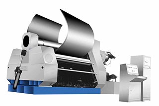
The Roll Bending Machine, also known as the Rounder or Roller Machine, is a versatile forming equipment used to roll metal plates into cylinders, cones, curves, and other shapes.
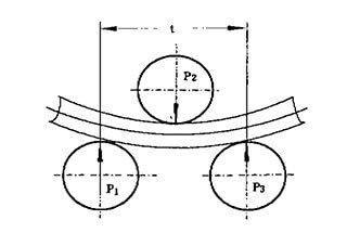
This machine works by using the principle of three-point forming circles, where the relative position change and rotational motion of the working rolls cause continuous plastic deformation of the metal sheet, resulting in the desired shape of the workpiece.
The Roll Bending Machine is widely used in industries such as boiler manufacturing, shipbuilding, petroleum, chemicals, metal structures, and machinery manufacturing.
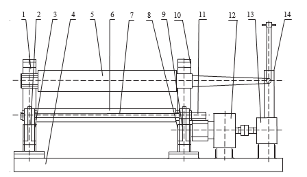
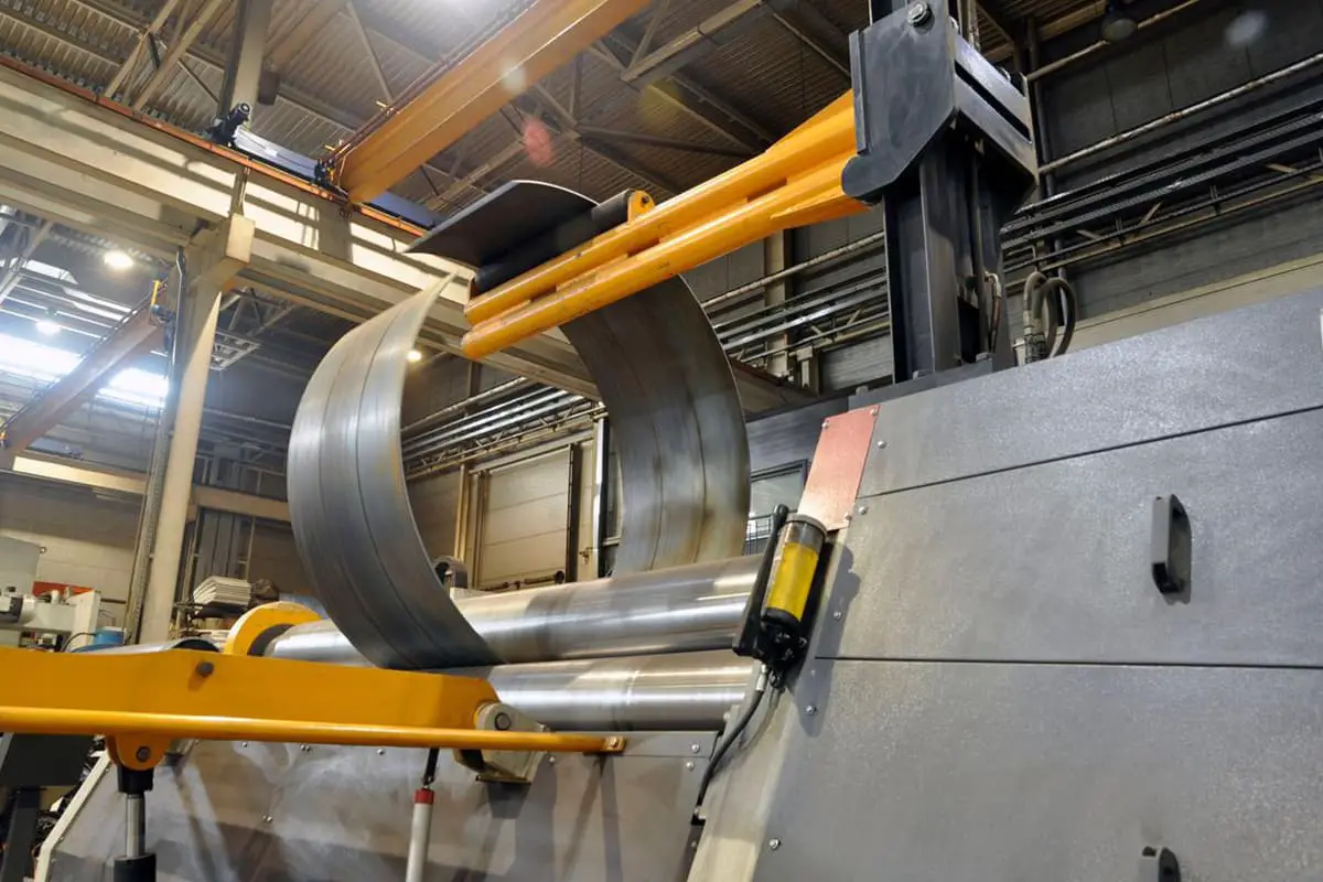
In a typical 3-Roll Bending Machine, two lower rolls function as active rolls and can rotate in both positive and reverse directions, while the upper roller serves as a follower roll, which can move up and down vertically. (See figure)
Movable bearing seat
Hydraulic cylinder
Left frame
Base
Upper roller
Lower roller
Tie rod
Right frame
Hydraulic cylinder
Fixed bearing seat
Roller gear
Reducer
Motor
Unloading device
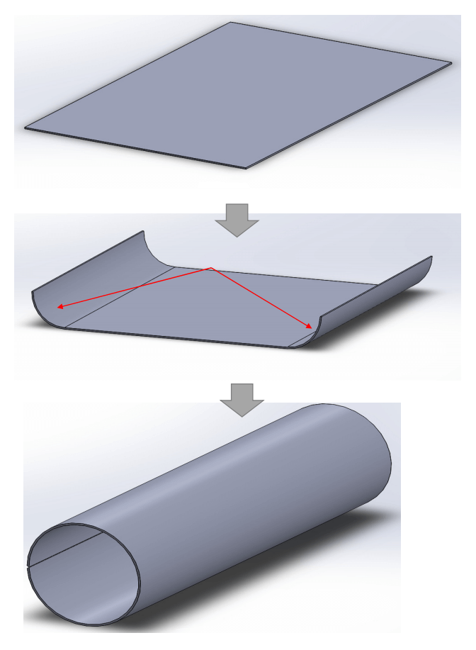
The process of rolling steel plate involves placing the plate between upper and lower rollers. The three cutting points exposed to the metal sheet by the three rolls cause the plate to bend into a curved or circular shape.
This process of sheet metal forming can be viewed as a continuous three-point bending process performed by the three-roll bending machine.
One end of the metal plate is fed into the machine between the upper and lower roller.
The top roller then applies downward pressure on the metal plate, causing it to undergo plastic bending deformation due to compression.
The rotation of the lower rollers, driven by friction between the plate and the rollers, causes the plate to move back and forth along its longitudinal direction.
The upper roller continues to exert downward pressure and moves back and forth on the plate.
As the plate passes through the roller deformation zone, plastic deformation occurs when stress exceeds the yield limit.
This results in the plate undergoing plastic bending deformation along its entire length and being shaped into the desired form.
By adjusting the relative position between the upper and lower rolls, the plate can be bent to a radius no less than that of the upper roller.
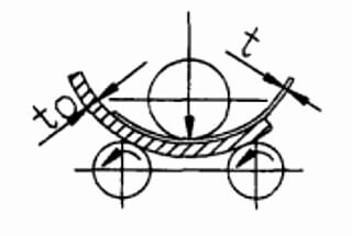
A diagram of the working principle of a symmetrical three-roll bending machine is provided below.
Driven rollers II and III are powered by a motor and a reducer and rotate in the same direction (or in opposite directions) at the same speed.
Due to the friction between the rollers and the plate, the plate is moved forward as the rollers rotate.
By adjusting the position of the upper roller, plates of varying curvatures can be produced.
If the workpiece doesn’t meet the desired curvature after a single rolling process, the upper roller can be adjusted and the process repeated until the desired shape is achieved.
The three rolls of the symmetrical three-roller bending machine are arranged in an isosceles triangle, causing the two ends of the workpiece to leave a straight-line segment in the rolling process.
This straight-line segment, which is about half the distance between the centers of the two lower rollers, is where the roller cannot roll and is the main disadvantage of this type of machine.
Despite its limitations, the symmetrical three-roller plate bending machine is widely used due to its simple structure, ease of operation, and low cost.
The problem of the straight-line segment can be addressed using different methods, depending on the specific situation, as shown in the table below.
Item
Solution
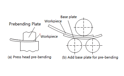
Elbow pre-bending
This technique involves using a die to pre-bend the ends of the steel plate in a press machine, so as to achieve the desired curvature.
Keep allowance
Add appropriate plate allowance at the ends of the plate. After rolling out a certain length at the two ends, the remainder (also known as the straight-line segment) can be cut off.
Add base plate for pre-bending
This method is carried out on the rolling machine, as depicted in figure 3b.
However, when adopting this method, it’s crucial to take into account the capacity of the rolling machine, that is, the combined bending force of the workpiece and the necessary gasket should not exceed that of the rolling machine.
For another asymmetric three-roller bending machine, the shaft roller arrangement is designed to eliminate straight line segments on the rolled workpiece.
The machine has the characteristic that the two lower rollers can be adjusted vertically. One lower roller can be adjusted to match the center distance of the upper roller, while the other is raised to the appropriate position.
The beginning end of the steel plate can be bent and rolled. After half a roll, the alignment of the two lower rollers is changed, and the rolling continues to eliminate the straight line segment at the end of the workpiece.
Alternatively, the workpiece can be turned over so that the back end becomes the front end for rolling, which will also eliminate the line segment.
3 Roll Bending Machine Rolling Process
Here is a brief overview of the process for rolling a short cylinder with a diameter of 400mm or greater, to help you understand the operation of a three-roller bending machine.
Getting the material
The material must be verified in accordance with the drawing and process requirements, and should have no obvious defects on its surface.
The material quality and specifications should conform to relevant national and industry standards.
Draw the line
When expanding, the cylinder’s diameter must match the actual diameter of the end enclosure, and the cylinder material’s diameter should be calculated based on the cylinder’s intermediate diameter.
The expanding direction should align with the steel rolling direction and be limited to a 45° position. The layout should be efficient, utilizing the edge material effectively and increasing the utilization of steel.
If the cylinder is constructed from multiple sections, the welding must be properly executed according to the technical requirements of equipment assembly and welding.
The spacing between butt welds of the end enclosure and longitudinal weldseams of the cylindrical shell section should be more than 3 times the cylinder’s thickness and not less than 100mm.
If the cylinder is connected to a pipe, support, reinforcing ring, base plate, etc., the interposition of the longitudinal and circumferential welds on the cylinder should prevent holes in the weld seam or being too close to it, and the reinforcing ring or base plate should cover the weld seams.
The line drawing should be precise, using a geometric mapping method to draw a vertical line, bisector, and midpoint, instead of a square master.
Allow for necessary margins, first draw the edge cutting line on the metal plate, then the actual material line, and verify the line.
Tolerance Requirements for Drawing Lines for Blanking:
The tolerance requirement for the line drawing of the cylinder height H is H ± 1mm.
The difference between two diagonal lines (△ L = L1 – L2) should be less than or equal to 2mm, and the length tolerance of the cylinder section is L ± 3mm.
The perimeter formula is L = π (Di + S), where Di is the cylinder diameter (mm) and S is the cylinder thickness (mm).
After marking, a material mark transplantation is made in the 100mm x 100mm box in the upper right corner of the steel plate.
Blanking and Edge Processing:
For carbon steel plates with a thickness less than 12mm, blanking is carried out using a shearing machine if possible (otherwise, a semi-automatic cutting machine is used).
After cutting, the slag should be cleaned and deburred.
For plates with a thickness greater than 6mm that require a groove, semi-automatic cutting machines or rolling chamfering machines are used. For plates with a thickness less than 6mm, the grinding method should be used.
The grooves generated by the flame cutting machine should have the slag cleaned, and the welding groove should not have flaws such as cracks or delaminations.
Before welding, the surface of the welded joint should be cleaned of any harmful impurities such as oxide, grease, and slag.
The clearance range (calculated from the groove or plate edge) should be ≥ 20mm.
Pre-bending
When rolling a plate, the ends of the plate can be bent due to the lack of contact with the upper roller, resulting in residual straight edges.
During symmetrical bending, the residual straight edge is typically about half the center distance of the lower roller and depends on the plate thickness.
Asymmetrical bending results in residual straight edges that are approximately 1/6 to 1/10 of those in symmetrical bending.
These residual straight edges can be challenging to eliminate completely during correction and can lead to quality issues and equipment accidents, so they should be pre-bent.
If pre-bending is not possible, they can be corrected using a template after the final roll.
Before bending, the steel plate surface and roller surface must be cleaned, and any rust, leather, wool, edges, corners, or rigid particles must be removed.
For example, when rolling stainless steel, the upper and lower rollers must be protected by wrapping them in tape or a special paint layer, and the protective layer must not have any rigid particles.
Center alignment
When the plate is inserted into the rolling machine, to prevent misalignment, the workpiece should be rotated, and the workpiece’s main axis should be aligned parallel to the roller shaft to ensure that the round rolling is of good quality.
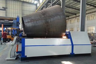
Rolling Circles
The circular rolling is the primary step in product forming and can be carried out in one-pass or multiple-pass processes.
The number of passes depends on the requirements of the process, such as the maximum permissible deformation rate in cold rolling, and the limitations of the equipment, such as the grip and power conditions.
A certain amount of over-rolling must be applied when the spring-back in cold rolling is significant.
The longitudinal stagger of the cylinder end should be less than 1.5mm. The plate rolling process is depicted in the accompanying figure.
Roundness correction
The purpose of roundness correction is to make the curvature of the entire circle as uniform as possible, thus improving product quality. Typically, the steps are:
(1) Feeding: Based on experience or calculation, the rollers can be adjusted to the maximum correct curvature position.
(2) Round Rolling: Roll the cylinder twice under correction curvature, focusing on the welding position to achieve consistent curvature throughout the circle.
(3) Unloading: Gradually decrease the load, allowing the workpiece to be rolled several times under reduced correction load.
As the founder of MachineMFG, I have dedicated over a decade of my career to the metalworking industry. My extensive experience has allowed me to become an expert in the fields of sheet metal fabrication, machining, mechanical engineering, and machine tools for metals. I am constantly thinking, reading, and writing about these subjects, constantly striving to stay at the forefront of my field. Let my knowledge and expertise be an asset to your business.
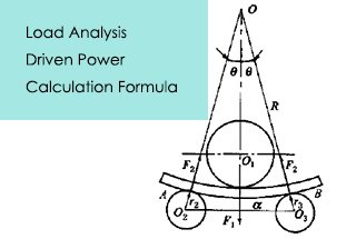
Imagine trying to bend a thick steel plate into a perfect cylinder—how much force would you need? This article dives into the critical calculations for determining the load and power…
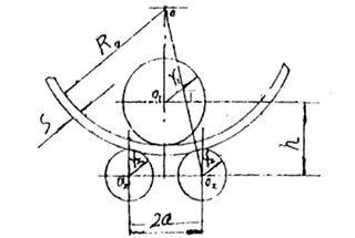
Have you ever struggled to calculate the center distance between rollers in a machine? In this blog post, we'll explore a straightforward method to determine this crucial measurement. Our expert…
Ever wondered who the top players in plate rolling machines are? This article introduces the leading manufacturers in the industry, detailing their innovations, product ranges, and global reach. From established…
Have you ever wondered how skilled operators bend steel plates into perfect cylinders? In this captivating blog post, we'll take you behind the scenes to explore the art and science…
Imagine transforming a flat sheet of metal into a complex curve with precision and efficiency. Roll bending machines, crucial in industries like shipbuilding and aerospace, achieve this through advanced technologies,…
Have you ever wondered how those massive steel structures are formed into perfect curves? Roll bending is the secret behind it. In this article, we'll dive into the fascinating world…
Have you ever wondered how a massive steel plate is bent into shape? In this article, we explore the fascinating mechanics behind plate rolling machines, revealing the forces and calculations…
Have you ever wondered how complex shapes like cones and cylinders are crafted from flat metal sheets? This article explores the fascinating process of roll bending, breaking down the steps…
Imagine transforming flat metal plates into precise cylinders or intricate shapes with just one machine. Welcome to the world of the plate roll bending machine! This powerful tool, essential in…