0° – 180° Bend Allowance Chart for Sheet Metal Bending
Have you ever wondered how sheet metal parts are designed and manufactured with precision? In this blog post, we'll dive into the fascinating world of bend allowance - a crucial…
Have you ever wondered how to achieve perfect sheet metal bends? This article dives into essential bending techniques, exploring everything from calculating material expansion to selecting the right tools. You’ll learn how to tackle common challenges, ensuring high-quality, efficient production. Whether you’re a seasoned technician or a curious beginner, this guide offers valuable insights to enhance your understanding and improve your results in sheet metal bending.
Bending forming is widely used in the shaping of sheet metal parts. This method is characterized by high efficiency, high-quality results, time savings, and cost savings in the processing of parts.
However, due to a lack of understanding of the bending process, process personnel often resort to traditional methods such as hand forming and hydraulic forming to achieve the final shape of parts.
These techniques increase the cost of part processing through the use of forming tools, can result in unstable parts due to increased human involvement, and reduce machining efficiency.
Therefore, it is crucial to have a thorough understanding of bending forming techniques.
Choosing the right bending technique requires careful consideration of many factors. Neglecting any of these considerations can result in process failure and negatively impact the development of parts.
In this article, we will primarily focus on calculating the size of expanded materials, selecting bending tools, analyzing typical part processing, and addressing common problems and solutions encountered during the bending process.
This article will serve as a guide for technologists and will be an important resource in the preparation of sheet metal parts. Its aim is to reduce the processing cost of parts and improve the quality and production efficiency of parts.
The focus of this article is to discuss size calculation, selection of bending tools, analysis of typical part processing, and common problems and solutions in the bending process.
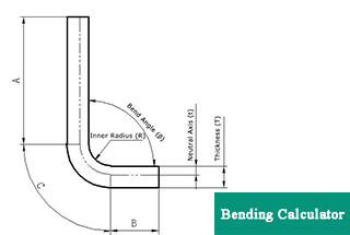
The size of sheet expansion depends on factors such as the thickness, material, bending angle, and bending tools. There are two commonly used methods for calculating the length of sheet metal expansion: the neutral layer calculation method and the empirical calculation method.
(1) The neutral layer calculation method
This method is appropriate for the situation where the bending angle is not a right angle. During the bending process, the outer layer experiences tensile stress while the inner layer experiences compressive stress.
The layer between these two layers, known as the neutral layer, experiences neither tensile nor compressive stress and remains unchanged throughout the bending process.
As a result, the neutral layer serves as the reference point for determining the length of the bent part.
However, the position of the neutral layer is dependent on the thickness of the material being bent.
Typically, if the material is less than 4mm thick, the distance between the neutral layer and the inner surface of the bent part is 0.5t. If the material is thicker than 5mm, this distance is 0.34t. The expansion length of the neutral layer is equivalent to the overall expansion length of the plate.
(2) Empirical calculation method
This method is only suitable for situations where the bending angle of the part is a right angle and the plate thickness is less than or equal to 3mm. It can be used to determine the expansion length of the parts.
The calculation formula is, L=A+B-2t
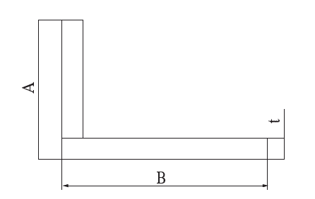
Fig.1 Part size schematic
(1) The selection principle of the press brake tooling
Selecting the appropriate tool for the bending process is a crucial consideration. The bending tool consists of two parts: the top tool (punch) and the bottom tool (die).
The choice of press brake punch and die is based on the thickness and size of the parts being bent to prevent deformation caused by collision between the parts and the punch and die.
The press brake is equipped with a universal lower die and a special die (as shown in figure 2). All notches for “V” shapes have a slot angle of 60 degrees. In general, the thicker the plate, the wider the slot should be, and the width of the slot is typically 8t.
For further information on the relationship between plate thickness and slot width, as well as how to calculate the required bending force, refer to the relevant article.
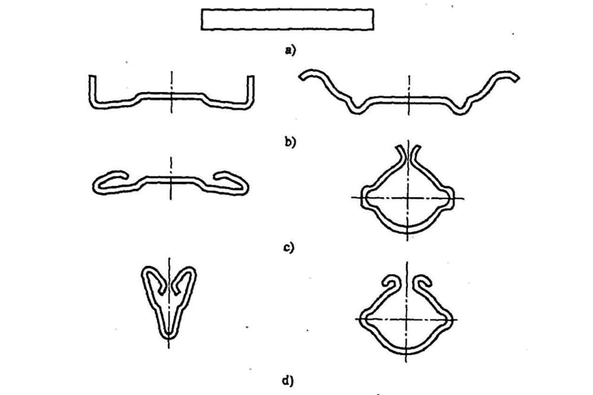
The press brake punch mainly includes straight punch, gooseneck punch, small bending punch, hemming punch etc., and can also customize the special tool according to the actual situation of the parts.
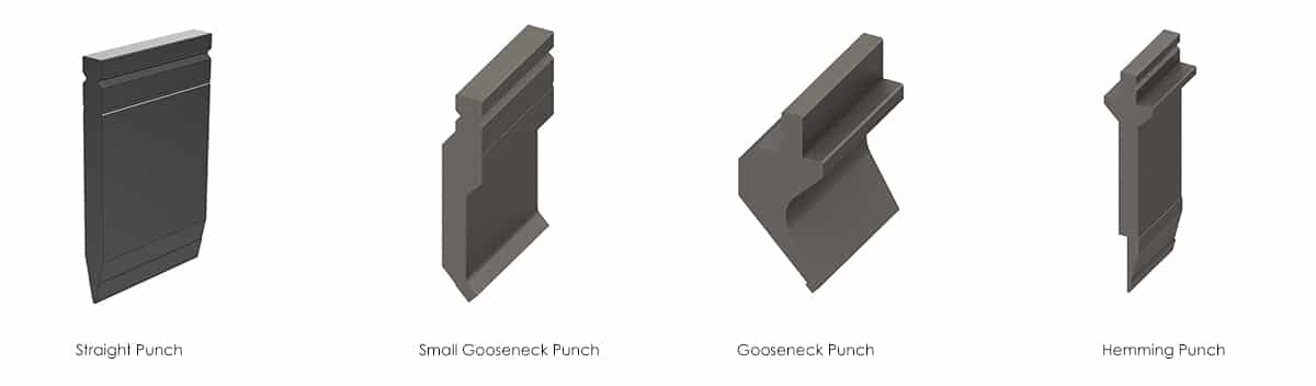
The straight punch is primarily utilized for bending parts with a thickness less than or equal to 3mm. The small gooseneck punch is mainly used for bending shallow “U” shaped parts.
The gooseneck punch is mainly used for bending “U” shaped parts with a deep depth. The hemming punch is mainly employed for flattening parts.
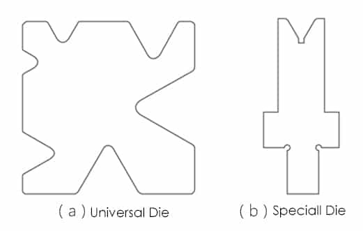
Fig.2
(2) The selection of press brake punch and die
Typically, we select the bending tool based on the bending radius of the part to guarantee that the bend radius is maintained. However, there are instances where the lower die is overlooked.
In such cases, an inappropriate combination of the bending punch and bending die can result in indentations on both sides of the bend radius after the bending process, making it impossible to repair.
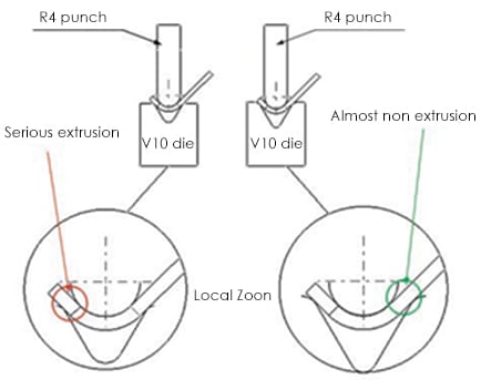
Fig.3 Bending punch and die matching simulation
Figure 3 displays the material thickness of 1.6mm for the simulated part, along with the bending radius R4 and a bending height of 8.9mm.
After conducting analysis, it was found that the lower die slot could be selected as either V12 or a smaller option. However, for this particular part, only the V12 slot could be chosen. The reasoning for this is shown in the figure, with the V10 slot on the left and the V12 slot on the right.
Considering the resilience of the part during bending, the angle input for the press brake controller must be less than 90 degrees.
As seen in the simulation figure for the 90 degree bending flange, if the punch of the press brake continues to move down, the V10 slot experiences significant extrusion while the V12 slot experiences minimal extrusion.
Therefore, it is recommended to select the lower die with the V12 slot instead of the V10 and smaller options. This will ensure that the two sides of the bend radius remain free of indentations and will not require any finishing, resulting in a qualified part.
When bending parts, it is important to consider both the height of the flange and the width of the web. If the width of the web is too narrow and the flange height is too tall, interference between the previously formed flange and the bending tool may occur during the bending process, preventing the continuation of the bend.
This can result in the scrapping of the entire batch of material, leading to increased processing costs if no corrective action is taken.
In the following analysis, we will examine the bending of “U” shape parts and “Z” shape parts.
Related reading: V & U-shaped Bend Force Calculator
(1) Technique analysis of “U” shape parts
The key factor in bending “U” shaped parts is the relationship between the height (H) of the two flanges and the width (B) of the web. If H is less than or equal to B, it is generally possible to bend the part, although interference may occur. This type of interference happens between the bending flange of the part and the machine body.
For a standard press brake machine, if the bending height H is greater than or equal to 80mm, the part will interfere with the machine during the bending process.
When faced with such interference issues, there are two solutions:
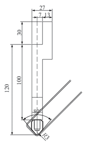
Fig.4 Suspension bending tooling
(2) Technique analysis of “U” shape parts
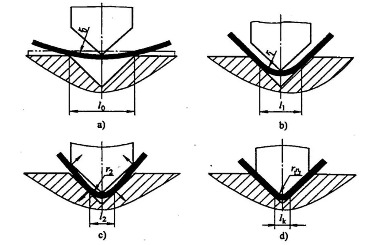
“Z” shaped parts with curved edges in sheet metal are known for their small size and high volume. If technicians use a conservative hand-forming process to produce these parts, the efficiency is low and the quality is inconsistent.
To avoid these issues, the parts must be simulated and analyzed before the bending process is chosen. This is because the size limitations of the part webs and the size of the bending die must be taken into consideration.
Table 1 provides a classification of the parameters that need to be considered in the simulation analysis.
Table 1 Simulation parameter setting

| The parameter setting | Code | Schematic diagram |
|---|---|---|
| Web width (measured in the model) | H | |
| Bending radius | R | |
| Material thickness | t | |
| Tooling width | T | |
| The length of the linear neutral layer on the web. | L | |
| 1/2 Neutral layer arc length | P |
By using the information in the table, technicians can accurately determine if the parts can be formed through bending. If the condition L + P is greater than T/2, then the bending process can be successfully carried out.
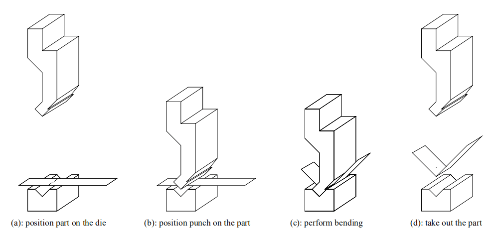
(1) Bending the flange of parts
Due to limitations in the punch and die equipment on the press brake, not all flanges with different heights can be formed using this method. Therefore, it is crucial to perform careful analysis and simulation before selecting the bending method to ensure that the parts can be bent.
CATIA can be used for technical analysis and preparation to simulate the feasibility of the bending height for the part. The following should be taken into consideration when conducting the simulation:
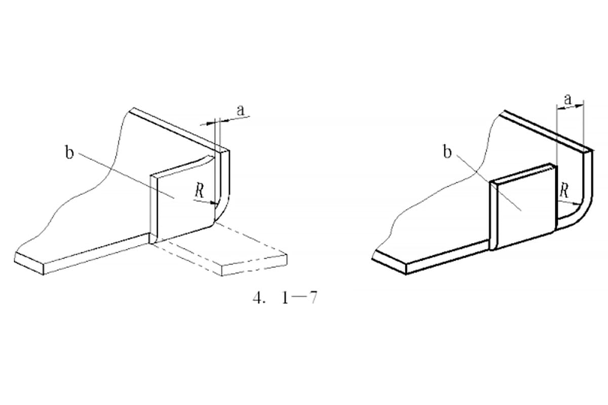
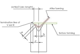
The simulation results are shown in Figure 5.
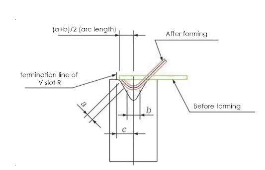
Fig. 5 Parts flange bending
In the formed state of Figure 5, the black line represents the neutral layer of the part. The variables “a” represents the linear dimension of the neutral layer, “b” represents the arc length of the neutral layer at the bending radius, and “c” represents the distance between the tool center and the termination line of the V slot R.
If (a + b)/2 is greater than c, the part can be bent. If (a + b)/2 is less than or equal to c, the part cannot be bent.
Based on this evaluation, if the size of the part is too small for bending, the overall flange size of the part needs to be increased when preparing the technique.
(2) Bending of large parts
When bending large length parts, the press brake machine can be impacted by its own machine tool structure, causing significant deformation in the bending beads of the parts. In theory, the bend should be a straight line, but after bending it becomes a curved line, requiring a significant amount of finishing work by the workers.
To address this issue, the crowning on the press brake can be adjusted based on the actual conditions after bending to eliminate the deformation of the parts, as shown in Figure 6. This reduces the amount of manual labor required and improves the quality of the parts and production efficiency.
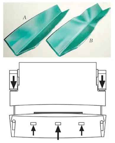
Fig. 6 Long parts bending and crowning
(3) Bending of parts with partially thinning
In sheet metal parts, some parts are partially reduced in size to decrease weight. These parts can be produced through hydraulic forming or bending in actual production. However, due to variations in the material thickness for bending, the same punch and die cannot be used for one-time bend forming.
To overcome this issue, thin paddings can be added to the thinned area of the material. The paddings are placed in the area corresponding to the top punch after bending.
During the bending process, the paddings will compensate for the punch and allow for bending of materials with different thicknesses in one step.
(4) Bending of the part with a shaped flange
Most standard rear positioning stoppers on press brakes are straight line types and can only bend parts with equal height flanges. However, this type of stopper is not suitable for parts with non-equal height flanges or shaped parts.
To address this, two solutions can be applied:
(1) Design a dedicated back stopper specifically for parts with non-equal height flanges and shaped parts. This stopper uses bolts for positioning, changing the conventional positioning method of the press brake machine and solving the problem of bending for parts with non-equal height flanges and shaped flanges. This also expands the capabilities of the press brake.
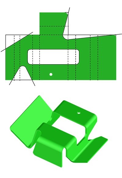
The pre-processing and post-processing states are shown in Figure 7 and Figure 8, respectively.
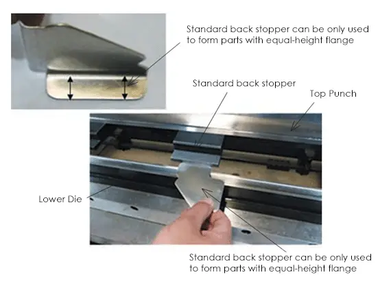
Fig.7 Pretreatment state

Fig.8 Post-processing state
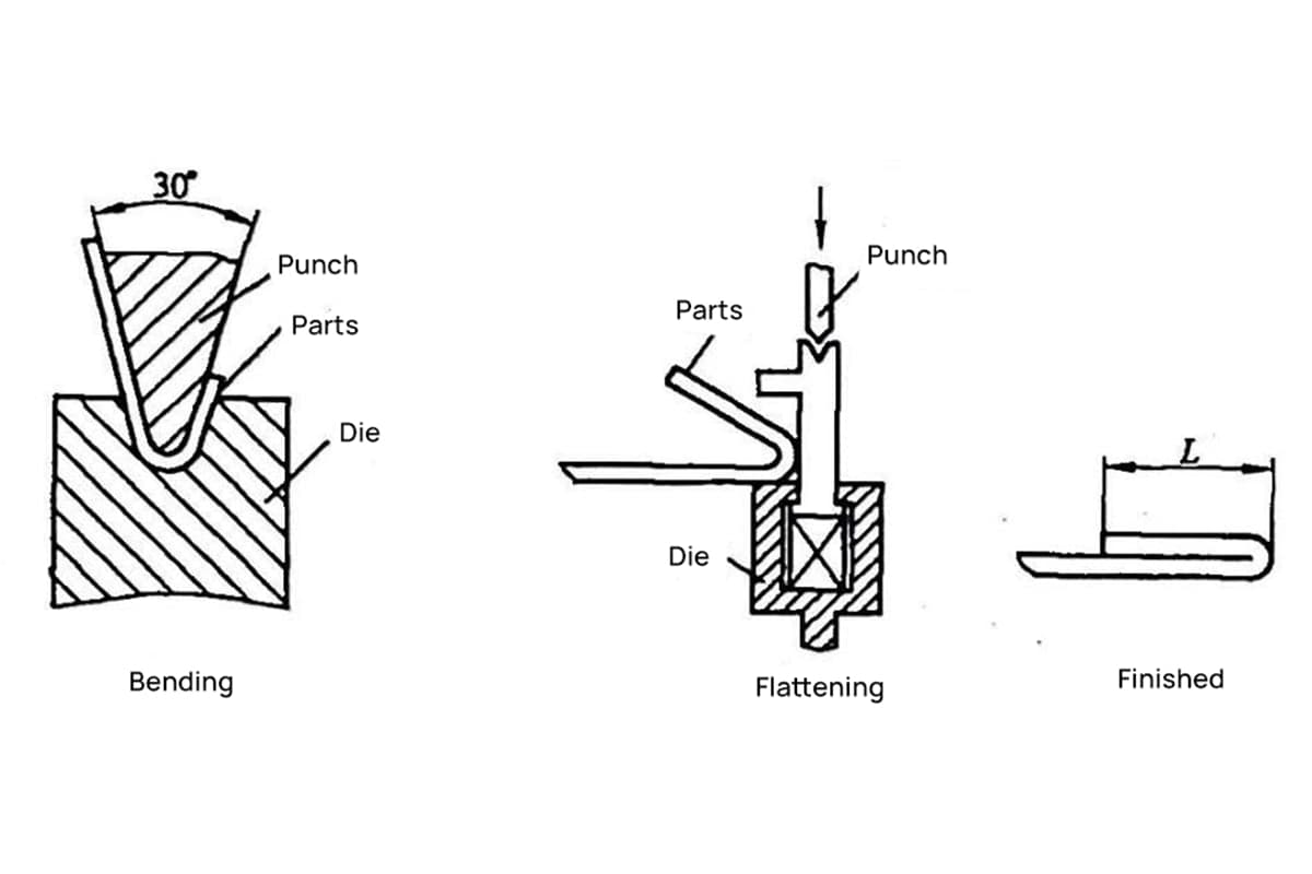
(2) Another solution is to add an assistant positioning earpiece to the bending parts during blanking. The earpiece is at the highest level of the parts and can be used for positioning during bending and forming. After bending, the earpiece is removed to complete the bend forming of the parts. This greatly improves production efficiency.
(5) The parts broke at the bending place
When some parts break at the bend position, there are two main factors that can cause this:
The discussion and analysis of various situations encountered in the bending technique have expanded the scope of the bending forming process in sheet metal parts production. This helps to avoid errors in process selection that would negatively impact the overall development cycle of the parts and improve production efficiency while stabilizing the quality of the parts.
The design of more reasonable bending tooling will play a crucial role in expanding the application of the bending forming technique.

As the founder of MachineMFG, I have dedicated over a decade of my career to the metalworking industry. My extensive experience has allowed me to become an expert in the fields of sheet metal fabrication, machining, mechanical engineering, and machine tools for metals. I am constantly thinking, reading, and writing about these subjects, constantly striving to stay at the forefront of my field. Let my knowledge and expertise be an asset to your business.