Motor Bearing Heat Generation: A Complete Analysis
Why do motor bearings get so hot, and what can be done about it? This article dives into the causes of motor bearing heat generation, from excessive loads and poor…
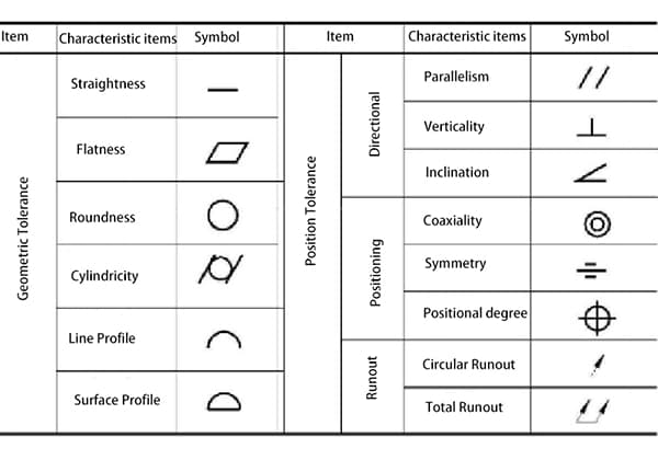
Have you ever wondered what makes a perfect circle? In the world of mechanical engineering, roundness is a crucial concept that affects the performance and longevity of rotating components. This article dives into the intricacies of roundness, exploring its definition, measurement methods, and the factors that influence it. Whether you’re a seasoned engineer or a curious learner, understanding roundness is key to designing and maintaining high-precision machinery.

In the Japanese Industrial Standard (JIS) B0621-1984, which pertains to the definition and expression of form and position deviations, roundness is defined as “the deviation from the geometric circle of a circular body.” This standard provides a precise method for representing roundness, which is crucial for ensuring the quality and functionality of circular components in mechanical engineering.
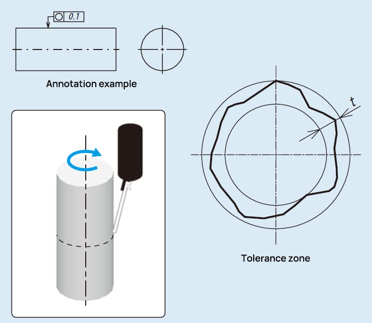
The representation of roundness in JIS B0621-1984 is as follows:
For rotating components, evaluating their true circular shape is critical to ensure proper function and longevity. The immediate concern is to determine the roundness tolerance, which is the permissible deviation from a perfect circle. This evaluation begins with:
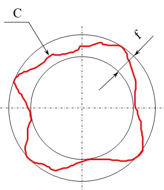
Roundness tolerance, also known as circularity tolerance, is a geometric dimensioning and tolerancing (GD&T) specification that defines the allowable deviation from a perfect circle in a cross-sectional plane of a cylindrical or spherical part. It ensures that the measured circumference of a part lies within a specified tolerance zone, which is the area between two concentric circles of the same section with a radius difference of t. This tolerance zone guarantees that the part maintains a consistent circular shape within the defined limits.
Imagine a cross-section of a cylindrical part. The roundness tolerance zone is depicted as the area between two concentric circles. The radius difference t between these circles represents the allowable deviation from the ideal circular form. Any point on the actual circumference of the part must fall within this zone to meet the roundness tolerance requirement.
Several factors can lead to deviations in roundness and cylindricity, affecting the precision and functionality of machined parts. Here are the common causes:
There are several methods for evaluating roundness, each with its own unique features and advantages. The method to use is typically selected based on the specific requirements of the workpiece.
Such as:
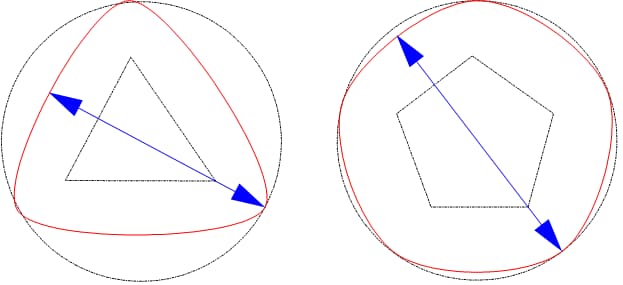
Diameter method
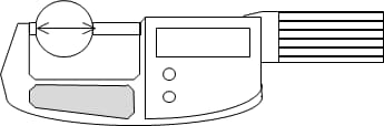
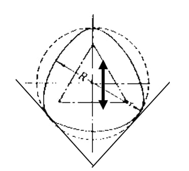
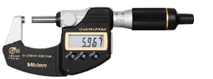
Roundness can be directly measured using tools such as micrometers. This method is simple and easy to perform. However, when evaluating triangle and pentagonal equal-diameter circles, it is easy to measure them as circular if they are not, leading to incorrect results.
Three point method
The three-point method can obtain roundness data through [V-block + micrometer / meter + bench].
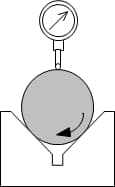
However, the three-point method may result in incorrect measurements due to differences in the tangent line at the selected support point and difficulties in determining the center of the reference point. Additionally, errors may occur during measurement due to the up and down movement with the rotation of the object being measured.
Such as:
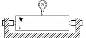
Radius method
The radius method evaluates the roundness by using the difference between the maximum and minimum radius obtained after rotating the workpiece for one cycle. As shown in the figure, the measurement results can also be easily impacted by the workpiece’s horizontal operation.
The tolerance zone is between two concentric circles on the same section
Central method
Compared with the central method, the radius method is mostly used for more precise measurement needs. The data of roundness detection depends on the reference circle. Different evaluation methods of the test circle will result in different central positions of the reference circle, thereby affecting the axial position of the measured circular feature.
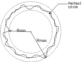
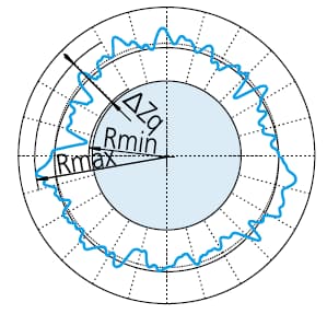
To determine roundness, the measured contour is fit to a circle and the sum of squares of the deviation of the contour data from the circle is minimized. Then, the roundness value is defined as the difference between the maximum deviation (the highest peak value to the lowest valley value) of the contour and the circle.
ΔZq=Rmax-Rmin, symbol representing roundness value through LSC
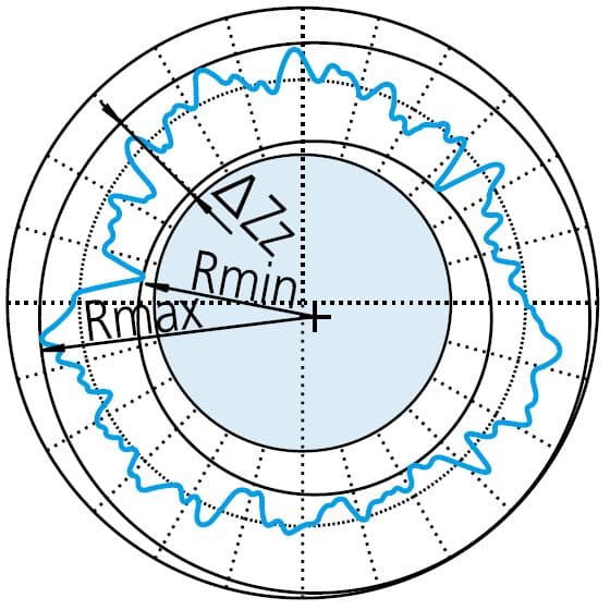
To minimize the radial difference, two concentric circles are placed around the measured contour. The roundness value is defined as the radial interval between the two circles.
ΔZz=Rmax-Rmin , symbol representing roundness value through MZC
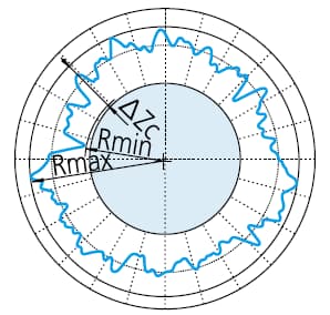
First, create the smallest circle that encloses the measured profile. Then, the roundness value is defined as the maximum deviation between the contour and the circle. This method is commonly used for evaluating shafts, rods, and similar objects.
ΔZc=Rmax-Rmin , the symbol of roundness value through MCC.
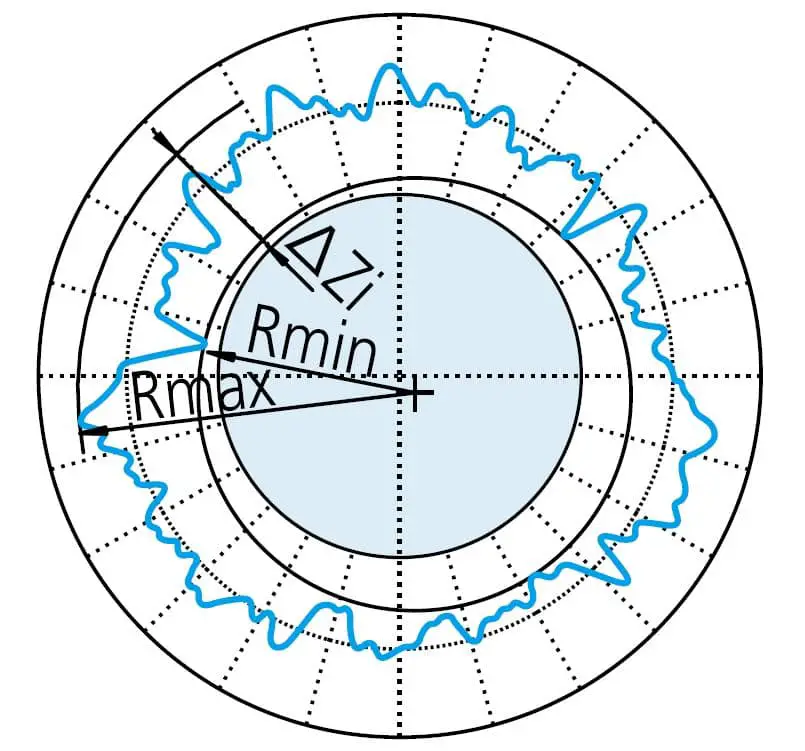
Create the largest circle that can enclose the measured profile. Then, the roundness value is defined as the maximum deviation between the contour and the circle.
ΔZi=Rmax-Rmin , the symbol indicating roundness value through MIC.
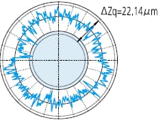
When evaluating roundness, the obtained contour is typically filtered to reduce or eliminate the influence of unnecessary noise.
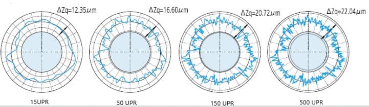
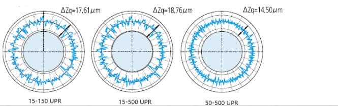
Filtering methods and the set filtering cut-off values (UPR: fluctuations per revolution) can vary depending on the specific measurement requirements. The figure below illustrates the varying effects of filter settings on the measured contour.
No filter:
Low pass filter:
Bandpass filter:
As evaluators, what can these figures tell us?
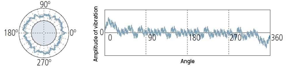
Figure: chart of measurement results
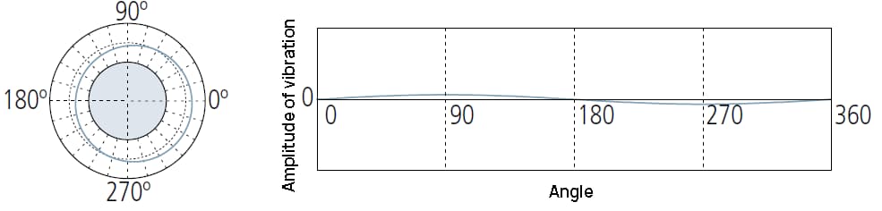
1 UPR: only one wave is retained after filtering:
1UPR component indicates the eccentricity of the workpiece relative to the rotating axis of the measuring instrument.
The amplitude of the waveform depends on the adjustment of its level.
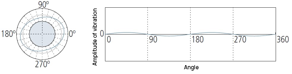
2UPR components may indicate:
① Insufficient level adjustment of measuring instruments;
② Circular runout caused by incorrect installation of the workpiece on the machine tool forming its shape;
③ The shape of the workpiece is oval in design, for example, in the piston of IC engine.
May indicate:
① Deformation caused by too tight retaining chuck on the measuring instrument.
② Relaxation deformation caused by stress release when unloading from the fixed chuck of the processing machine tool.
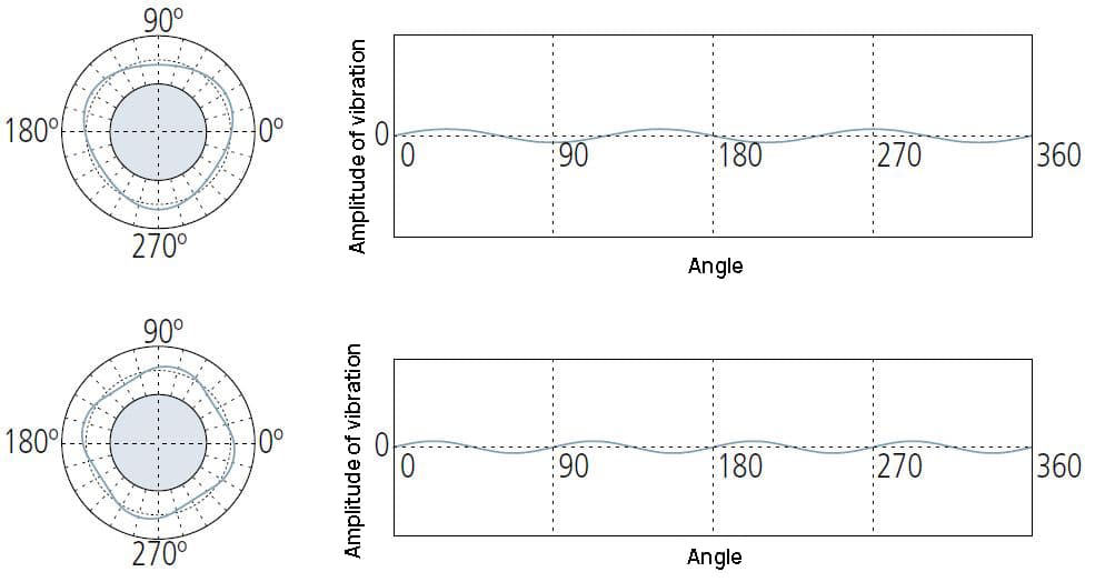
It usually refers to unbalanced factors in the processing method or the process of producing workpieces.
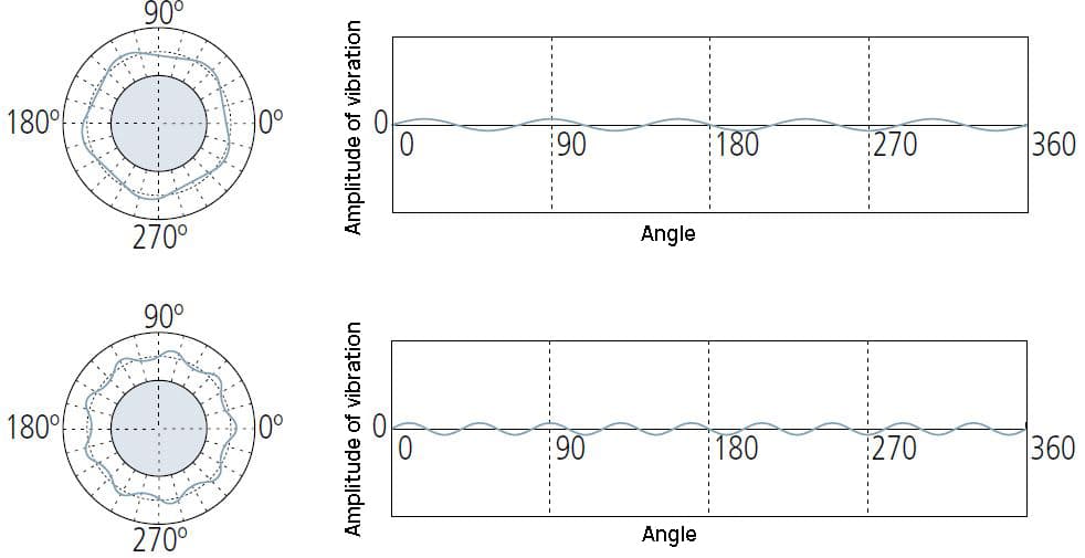
15 (or more) UPR conditions are usually caused by their own causes, such as tool chatter, machine vibration, coolant transfer effect, material inhomogeneity, etc.

| Parameter | Meaning |
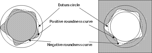
| RONt | The measured value of roundness represents the difference between the maximum value of positive roundness curve and the minimum value of negative roundness curve or the sum of absolute values. |
| RONp | The measured peak height of roundness curve represents the maximum value of positive roundness curve. |
| RONV | The measured value of roundness represents the absolute value of the minimum value of the negative roundness curve. |
| RONq | The double root mean square roundness measurement represents the double root mean square of the roundness curve. |
Finally, let’s take a look at what tools and instruments are available to measure roundness?
Micrometer:
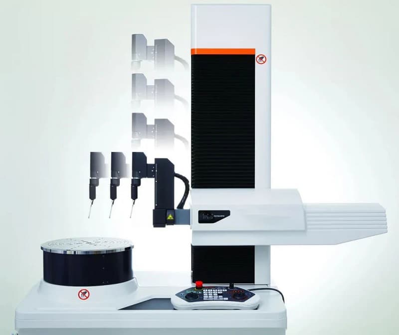
Roundness measuring instrument:
Coordinate measuring machine:

The space is limited, and you are welcome to leave a message and criticize the matters not covered.
After reading this article, I hope you have gained a deeper understanding of roundness. If you have any further questions, please feel free to leave a comment below.

As the founder of MachineMFG, I have dedicated over a decade of my career to the metalworking industry. My extensive experience has allowed me to become an expert in the fields of sheet metal fabrication, machining, mechanical engineering, and machine tools for metals. I am constantly thinking, reading, and writing about these subjects, constantly striving to stay at the forefront of my field. Let my knowledge and expertise be an asset to your business.