Have you ever wondered how engineers ensure precision and accuracy in manufacturing? In this blog post, we’ll delve into the fascinating world of geometric tolerances – a crucial aspect of mechanical engineering that enables the production of high-quality components. Drawing from the expertise of seasoned professionals, we’ll explore the various types of tolerances and their applications, providing you with valuable insights to enhance your understanding of this complex subject. Get ready to discover the secrets behind achieving perfection in the realm of mechanical engineering!
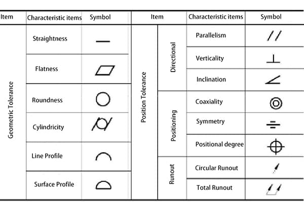
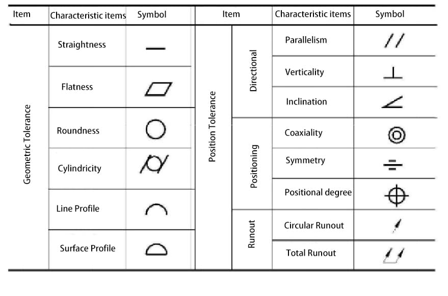
The geometric tolerance specified by the national standard is divided into two categories: geometric tolerance and position tolerance, a total of 14 items.
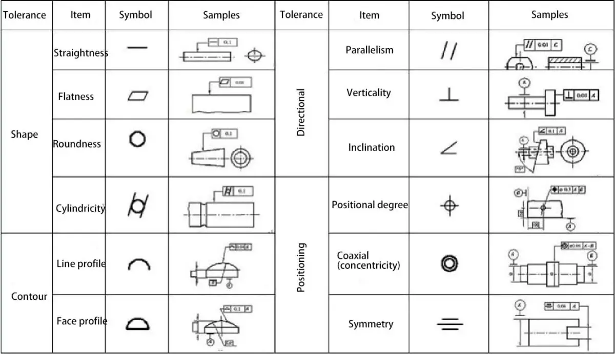
Their names and symbols are shown in the table below.
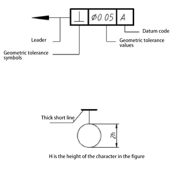
Geometric tolerance symbols
I. Definition of Geometric Positioning Tolerance
Straightness – All points are on a straight line, with tolerance specified by the region between two parallel lines.
Flatness – All points on a surface are on a plane, with tolerance specified by the region between two parallel planes.
Roundness – All points on a surface are on a circumference, with tolerance specified by the region between two concentric circles.
Cylindricity – The axis of all points on a rotating surface is equidistant from a common axis. Cylindricity tolerance defines the tolerance region formed by two concentric cylinders, where this rotating surface must fall within this region.
Profile tolerance – Defines the tolerance method for irregular surfaces, lines, arcs or ordinary planes. Profile can be applied to a single line element or the entire surface of a part. Profile tolerance specifies the unique boundary along the actual profile.
Perpendicularity – The surface or axis is perpendicular to the datum plane or axis. Perpendicular tolerance specifies one of the following: the region defined by two planes perpendicular to the datum plane or axis, or the region defined by two parallel planes perpendicular to the datum axis.
Parallelism – The surface or axis and all points are equidistant from the datum plane or axis. Parallelism tolerance specifies one of the following: the region defined by two parallel planes or lines parallel to the datum plane or axis, or the cylindricity tolerance region where the axis is parallel to the datum axis.
Coaxiality – The axis of all intersecting combinable elements of the rotating surface is the common axis of the data feature. Coaxiality tolerance specifies the cylindricity tolerance region where the axis is the same as the datum axis.
Position tolerance – Position tolerance defines the area where the center axis or center plane is allowed to deviate from the actual (theoretically correct) position.
The basic dimension establishes the actual position between the data feature and the interrelated feature. Position error is the total allowable positional deviation between the feature and its correct position.
For cylindrical features such as holes and external diameters, position tolerance is usually the diameter of the tolerance region where the axis of the feature must fall. For non-circular features (such as slots and short projections), position tolerance is the total width of the tolerance region where the center plane of the feature must fall.
Circular runout – Provides control over circular surface elements. When the part rotates 360 degrees, this tolerance is independently applied at any measurement position of the circular element and applied to the circular runout tolerance constructed around the datum axis, controlling the accumulated change in roundness and coaxiality.
When applied to a surface constructed vertically with the datum axis, it controls circular elements of plane surface features.
Total runout – Provides composite control over all surface elements. When the part rotates 360 degrees, this tolerance is applied simultaneously to both circular and elongated features. When applied to a surface constructed around the datum axis, total runout controls the accumulated variability of roundness, cylindricity, straightness, coaxiality, angle, taper, and profile. When applied to a surface constructed vertically with the datum axis, it controls the accumulated variability of perpendicularity and straightness.
II. Basic Terminology
Feature – refers to the points, lines, and surfaces that make up the geometry of a component.
Ideal feature – a feature with geometric meaning.
Actual feature – the feature that actually exists on the component, typically represented by a measured feature.
Reference feature – a feature used to determine the direction or position of the measured feature. Simply referred to as a reference, it serves as the basis for determining the geometric relationship between features. It includes reference points, reference lines, and reference surfaces.
Measured feature – the feature that specifies the shape or position tolerance.
Central feature – points, lines, or surfaces that have a symmetrical relationship with the feature.
Tolerance band – restricts the variation of actual shape or position features. It is a region defined by a given maximum error value, determined by size, shape, direction, and position.”
III. Tolerance Classification
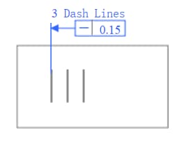
1. Straightness
The tolerance band is the region between two parallel lines/planes/cylinders, etc. at a distance of tolerance value t
Example 1
Each engraved line must be located between two parallel lines on the surface with a tolerance value of 0.015mm
Example 2
Any element line on the cylindrical surface must be located within the axial plane and between two parallel lines at a distance of tolerance value 0.02mm.
Application Example
Example 3
Any element line on the cylindrical surface must be located within the axial plane and between two parallel lines at a tolerance value of 0.04mm within any 100mm.
Example 4
Discussion: How should we understand if different straightness tolerances are given in two directions on the same surface?
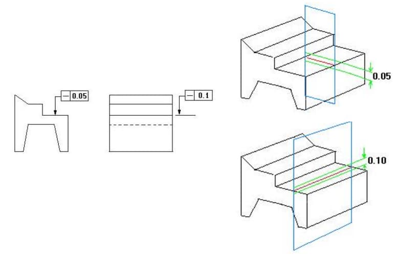
2. Flatness
The tolerance band is the region between two parallel planes at a distance of tolerance value t.
It represents the actual shape of the component’s planar features retaining the ideal plane condition.
Example 1
The upper surface must be located within two parallel planes at a tolerance value of 0.1mm.
Example 2
Any 100×100 range on the surface must be located within two parallel planes at a tolerance value of 0.1mm.
3. Roundness
It represents the actual shape of the circular feature on the component and its center maintaining an equal distance.
The tolerance band is the region between two concentric circles with a radius difference of tolerance value t on the same cross-section.
Example 1
In any cross-section perpendicular to the axis, the circle must be located between two concentric circles with a radius of tolerance value 0.02mm.
Example 2
In any cross-section perpendicular to the axis, the circle must be located between two concentric circles with a radius of tolerance value 0.02mm.
4. Cylindricity
It represents the condition where all points on the contour of the cylindrical surface on the component maintain equal distance from its axis.
The tolerance band is the region between two cylindrical surfaces with a radius difference of tolerance value t on the same axis.
Example 1
The cylindrical surface must be located between two cylindrical surfaces with a radius difference of tolerance value 0.05mm on the same axis.
5. Parallelism
It represents the condition where the actual measured feature on the component maintains an equal distance from the reference.
When given one direction, the tolerance band is the region between two parallel planes at a distance of tolerance value t and parallel to the reference plane (or line, axis); when given two perpendicular directions, it is the region within a rectangular prism with dimensions of tolerance values t1×t2 and parallel to the reference axis.
Example 1
The top surface must be located between two parallel planes at a distance of tolerance value 0.05mm and parallel to the reference plane.
Example 2
The axis of ΦD must be located between two parallel planes at a distance of tolerance value 0.1mm and vertically parallel to the reference axis Φ.
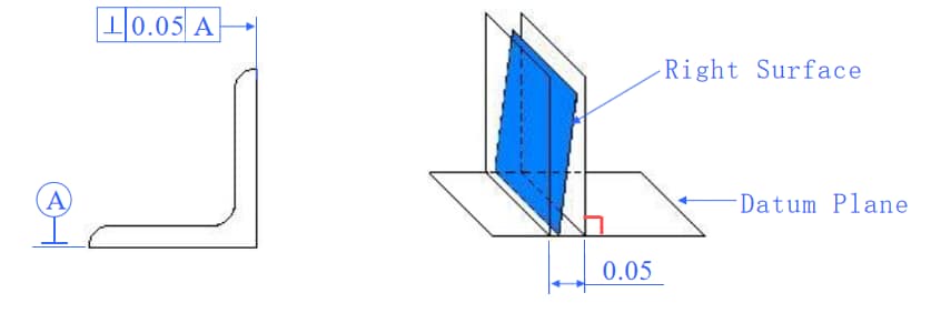
6. Verticality
The tolerance represents the condition where the actual feature on the part is maintained at a correct 90-degree angle relative to the reference feature.
When given a direction, the tolerance zone is the region between two parallel planes (or lines) that are perpendicular to the reference plane (or line, axis) and separated by a distance equal to the tolerance value t.
When two mutually perpendicular directions are given, the tolerance zone is the region inside a parallelepiped with dimensions t1 × t2 that is perpendicular to the reference axis.
Example 1
The right surface must be located between two parallel planes that are perpendicular to the reference plane and have a deviation of 0.05mm.
Example 2
The left surface must be within a deviation band of 0.05mm and between two parallel planes perpendicular to the reference axis.
Example 3
The axis of cylinder d must be located within the cylinder surface perpendicular to the reference plane with a diameter tolerance of 0.05mm.
Example 4
The axis of circular hole E must be between two parallel planes perpendicular to reference plane Z, with a deviation value of 0.06mm.
7. Tilt degree
Correct condition of two elements on the part maintaining a given angle between their relative directions.
Within a specified direction, the tolerance zone is the area between two parallel planes (or lines) that are at a theoretical correct angle to the datum plane (or line or axis) and at a distance of tolerance value t from it.
Example 1
The inclined surface must be located between two parallel planes that are at a 45-degree angle to the datum plane and at a distance of 0.08mm from it within the tolerance zone.
Example 2
The axis of feature D must be located between two parallel planes that are at a 45-degree angle to the datum axis and at a distance of 0.1mm from it within the tolerance zone.
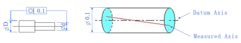
8. Concentricity
Concentricity is the condition where the axis being measured on the part maintains alignment with the datum axis along the same straight line.
The tolerance zone is the area within a cylinder that has a diameter of the tolerance value t and is coaxial with the datum axis.
Example 1
The axis of feature D must be located within a cylinder that has a diameter of 0.1mm and is coaxial with the datum axis D within the tolerance zone.
9. Symmetry
Symmetry is the condition where two pairs of symmetrical features on the part are aligned within the same plane.
The tolerance zone is the area between two parallel planes (or lines) that are at a distance of tolerance value t from the datum center plane (or center line or axis) and symmetrically arranged with respect to it.
If two mutually perpendicular directions are specified, the tolerance zone is the region within a four-sided prism whose cross-section is equal to tolerance values t1 x t2.
Example 1
The center plane of the slot must be located between two parallel planes that are symmetrically arranged with respect to the datum center plane and at a distance of 0.1mm from it within the tolerance zone.
Example:
CT MT Terminal
(1) The center of the terminal must be straightened.
(2) The maximum deviation of one side from the center of the slot cannot exceed 0.035mm.
Question?
(1) How is the offset T calculated?
T=(b-a)/2
(2) What is the symmetry tolerance?
10. Positional tolerance.
Positional tolerance refers to the accuracy of points, lines, surfaces, and other elements on a part in relation to their ideal locations.
Tolerance zone:
(1) Positional tolerance of point: The tolerance zone is the area within a circle or sphere with a diameter of the tolerance value t, centered on the ideal position of the point.
(2) Positional tolerance of line: When a direction is given, the tolerance zone is the area between two parallel planes (or lines) that are symmetrically arranged around the ideal position of the line and at a distance of the tolerance value t. If two perpendicular directions are given, the tolerance zone is the area within a four-sided prism with a cross-sectional size of t1 X t2 and the axis line of the prism coinciding with the ideal position of the line.
(3) Positional tolerance of surface: The tolerance zone is the area between two parallel planes that are symmetrically arranged around the ideal position of the surface and at a distance of the tolerance value t.
Example 1
The point must be located within a circle with a diameter of tolerance value 0.3mm, and the center of the circle is at the ideal position of the points determined by the relative datum A and B.
Three datum plane system:
Three mutually perpendicular datum planes A, B, and C constitute a datum plane system, commonly known as the three datum plane system. It is the starting point for determining the geometric relationships of various elements on parts.
In the three datum plane system, the datum planes are ordered by their functions.
The most important is the first datum plane (A), followed by the second (B) and third (C) datum planes.
Example 2
The axis of the hole must be located within a cylinder surface with a diameter of tolerance value 0.1 mm, and the axis line of the cylinder surface should coincide with the ideal position of the points on relative datum A, B, and C.
Example 3
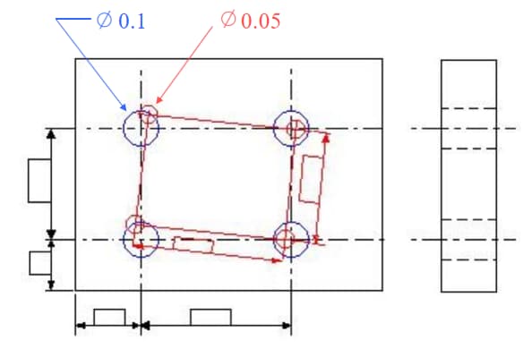
Composite positional tolerance.
Geometric frame:
It is a graphic that shows the correct geometric relationship between a set of ideal axis lines or between them and the datum.
The axis of the four D-holes must be located within the overlapping section of two cylindrical tolerance zones, one with a diameter tolerance value of 0.1 mm and the other with a diameter tolerance value of 0.05 mm. The geometric frame of the four 0.1mm positional tolerance zones is determined relative to datum A, B, and C. The geometric frame of the four 0.05mm positional tolerance zones is oriented only relative to datum A.
The axes of the four D-holes must be located within the overlapping section of two cylindrical tolerance zones, one with a diameter tolerance value of 0.1mm and the other with a diameter tolerance value of 0.05mm. The geometric frame of the four 0.1mm positional tolerance zones is determined relative to datum A, B, and C. The geometric frame of the four 0.05mm positional tolerance zones is oriented only relative to datum A.
Consideration: Comparing the following two types of positional accuracy.
11. Circular runout
Refers to the condition where the rotating surface on the part is limited within the measuring surface, and maintains its specified position relative to the reference axis.
(1) Radial runout.
The tolerance zone is the area between two concentric circles with their centers on the reference axis, where the radius difference in any measuring plane perpendicular to the reference axis is the tolerance value t.
(2) End face runout.
The tolerance zone is the cylindrical surface area along the generatrix direction with a width of t on the measuring cylinder at any diameter position coaxial with the reference axis.
Example 1
Radial runout.
When the cylindrical surface rotates around the reference axis without any axial movement, the radial runout in any measuring plane must not exceed the tolerance value of 0.05mm.
The tolerance zone is the area between two concentric circles with their centers on the reference axis, where the radius difference in any measuring plane perpendicular to the reference axis is the tolerance value t.
Example 2
End face runout.
When the part rotates around the reference axis without any axial movement, the axial runout at any measuring diameter on the left end face must not exceed the tolerance value of 0.05mm.
The tolerance zone is the cylindrical surface area along the generatrix direction with a width of t on the measuring cylinder at any diameter position coaxial with the reference axis.
12. Total runout.
Refers to the even runout along the entire measured surface of the part when it rotates continuously around the reference axis
(1) Radial total runout.
The tolerance zone is the area between two cylinders coaxial with the reference axis and having a radius difference of the tolerance value t
(2) End face total runout.
The tolerance zone is the area between two parallel planes perpendicular to the reference axis and having a distance of the tolerance value t.
Example 1
Radial total runout.
When the surface rotates continuously around the reference axis without any axial movement, while the indicator moves linearly parallel to the reference axis, the runout along the entire surface must not exceed the tolerance value of 0.02mm.
The tolerance zone is the area between two cylinders coaxial with the reference axis and having a radius difference of the tolerance value t.
Example 2
End face total runout.
When the end face rotates continuously around the reference axis without any axial movement, while the indicator moves linearly perpendicular to the reference axis, the runout along the entire end face must not exceed the tolerance value of 0.05mm.
The tolerance zone is the area between two parallel planes perpendicular to the reference axis and having a distance of the tolerance value t.
As the founder of MachineMFG, I have dedicated over a decade of my career to the metalworking industry. My extensive experience has allowed me to become an expert in the fields of sheet metal fabrication, machining, mechanical engineering, and machine tools for metals. I am constantly thinking, reading, and writing about these subjects, constantly striving to stay at the forefront of my field. Let my knowledge and expertise be an asset to your business.
Attention all mechanical engineers and manufacturing professionals! Are you struggling with pesky anodizing defects in your aluminum products? Look no further! In this blog post, we'll dive deep into the…
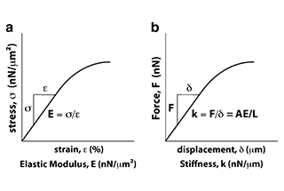
Ever wondered why some materials bend easily while others remain rigid? This blog dives into the fascinating world of elastic modulus and stiffness, unraveling their crucial roles in engineering. By…
Have you ever wondered what makes a perfect circle? In the world of mechanical engineering, roundness is a crucial concept that affects the performance and longevity of rotating components. This…
In today's fast-paced manufacturing world, efficient deburring is crucial. With numerous methods available, choosing the right one can be daunting. In this blog post, we'll explore various deburring techniques, from…
Have you ever wondered what keeps the world spinning smoothly? The unsung heroes behind the scenes are bearings. These small but mighty components play a crucial role in reducing friction…
Gears are the unsung heroes of the mechanical world, quietly working behind the scenes to keep machines running smoothly. But have you ever wondered what materials these critical components are…
This article explores the top 5 cooling tower manufacturers shaping our world. Learn how these companies innovate to keep industries running smoothly and efficiently. Get ready to uncover the secrets…
Have you ever wondered what keeps our gas systems running smoothly and safely? In this article, we explore top gas regulator manufacturers, uncovering their innovations and contributions to the industry.…
Ever wondered why connecting copper and aluminum wires is problematic? This article explains the risks associated with connecting these two metals due to their differing electrochemical properties, which can lead…