Sheet Metal Joining Process: The Ultimate Guide
Have you ever wondered how sheet metal parts are joined together to create complex structures? In this blog post, we'll explore the fascinating world of sheet metal joining techniques. As…
How does one transform a simple sheet of metal into a precise, functional component? Sheet metal cutting is a fundamental process in manufacturing that involves various techniques such as laser, plasma, and waterjet cutting. This article provides a comprehensive guide to these methods, exploring the principles behind each and their applications. From understanding the equipment used to the intricacies of different cutting methods, you’ll gain valuable insights into the world of sheet metal fabrication. Discover the details that make precision cutting possible and how these processes contribute to efficient production.
The principle of laser cutting is based on the abbreviation of Light Amplification by Stimulated Emission of Radiation, which is translated as laser.
Laser cutting is powered by electrical discharge and uses a mixture of gases such as He, N2, CO2, etc. as the excitation medium. The laser beam is generated by focusing the laser through a set of mirrors, which then melts the material.
The process of laser cutting: Under the control of NC programs, the laser generator produces a specific type of laser. The laser is transmitted through the optical system to the cutting head and focused on the surface of the workpiece, melting the metal.
At the same time, the assist gas is sprayed from the direction parallel to the laser beam to blow away the molten slag. The cutting head moves along the predetermined path, controlled by a servo motor, to cut out various shapes of workpieces.
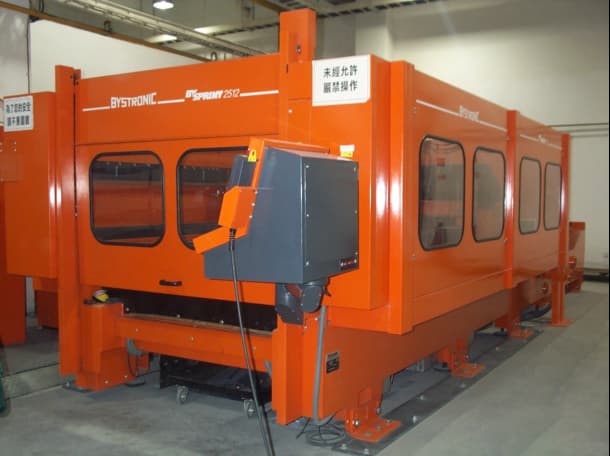
1)Machine Bed:
The entire optical path is mounted on the machine bed, which is equipped with beams, cutting head brackets, and cutting head tools. The bed is designed to eliminate vibrations during processing due to axial acceleration. The bottom of the machine bed is divided into several exhaust chambers. When the cutting head is located above a certain exhaust chamber, the valve opens and the waste gas is expelled. Through the bracket separator, small workpieces and scrap fall into the waste box.
2)Worktable:
The worktable with embedded supports is used to support the material during flat cutting.
3)Sensors:
Good cutting quality is related to the distance between the nozzle and the workpiece. There are two types of sensors: contact mechanical sensors and capacitance induction sensors. The former is used for processing non-conductive materials, while the latter is used for conductive materials.
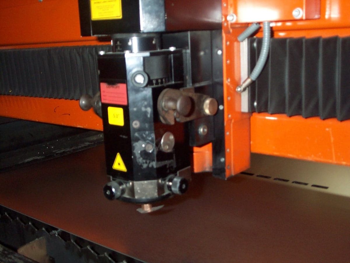
4)Cutting Head:
It is the final component of the optical path. The built-in lens focuses the laser beam. There are two standard cutting head focal lengths, 5 inches and 7.5 inches (mainly used for cutting thick plates).
5)CNC Controller:
Converts the cutting program (the pattern of the workpiece combination and layout) and the processing parameters of axis movement. Through the combination of movement of the beam, bracket, and rotary axis, the controller controls the movement trajectory of the laser beam on the workpiece, automatically adjusting the cutting speed and laser power.
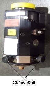
6)Laser Control Cabinet:
Controls and checks the function of the laser and displays the system’s pressure, power, discharge current, and laser operating mode.
7)Laser:
The resonant cavity is the heart of the laser, where the laser beam is generated. The laser gas is a mixture of carbon dioxide, nitrogen, and helium gases. The turbocharger causes the gas to move rapidly along the axis of the resonant cavity. The gas is cooled in the two heat exchangers to transfer energy to the gas in the high-pressure unit.
8)Cooling Equipment:
Cools the laser, laser gas, and optical system.
9)Dust Collector:
Removes most of the dust generated during processing.
10)Automatic Loading and Unloading System.
Cutting Methods:
1)Laser Melting Cutting – In laser melting cutting, the material of the workpiece is partially melted and the molten material is blown away by gas, forming a cut. The cutting is performed only in a liquid state, so it is called melting cutting. During cutting, a high-purity inert gas is supplied in the direction of the laser axis as the assist gas, and the assist gas only blows out the molten metal from the cut. It does not react with the metal.
2)Laser Flame Cutting – Unlike laser melting cutting, laser flame cutting uses active oxygen as the assist gas. Because oxygen reacts with the already heated metal, releasing a large amount of heat, the result is that the material is further heated.
3)Laser Vaporization Cutting – In laser vaporization cutting, the material at the cut is vaporized by the extremely high energy density. This method cuts the metal by quickly evaporating it, avoiding the splashing of molten droplets.
The choice of cutting method depends on their characteristics and the material of the plate, and sometimes the shape of the cut.
Since vaporization requires more heat than melting, the speed of laser melting cutting is faster than that of laser vaporization cutting, and laser flame cutting is faster by using the heat generated by the reaction of oxygen and metal.
At the same time, the cut width and roughness of flame cutting are high, and the heat-affected area is large, so the cutting quality is relatively poor, while the melting cutting has a smooth and high-quality surface, and the vaporization cutting has the best cutting quality without oxidation.
In addition, melting and vaporization cutting can obtain an oxygen-free cut, which is important for cutting with special requirements.
Generally, materials can be cut by flame cutting, if the surface is required to be non-oxidized, melting cutting should be selected, and vaporization cutting is generally used in cases with high requirements for dimensional accuracy and surface smoothness, so its speed is also the lowest.
In addition, the shape of the cut also affects the cutting method. When processing delicate workpieces and sharp angles, flame cutting may be dangerous because overheating can cause small parts to burn.
LASER Gas
During the actual Laser cutting process, auxiliary gas is also involved. Auxiliary gas can not only blow away the slag in time but also play a role in cooling the workpiece and cleaning the lens.
Choosing different auxiliary gases can also change the cutting speed and cutting surface quality, which is of great significance for cutting special metals.
1)Laser Gas
Laser gas is a mixture of helium, nitrogen, and carbon dioxide gas in a certain proportion, which is predetermined in the factory to ensure optimal performance.
Do not adjust the ratio casually, as improper proportions may cause laser system failure and damage to the high-voltage power supply.
Carbon dioxide CO2: is the activating substance. It is excited by electrical discharge and then converts the electrical energy into infrared radiation.
Nitrogen N2: transfers the energy generated by the electrical discharge to carbon dioxide, increasing the laser’s output power.
Helium He: can help maintain the electrical discharge in the gas and make carbon dioxide easier to cool.
2)Cutting Gas:
Mainly N2 or O2. The cutting surface of N2 cutting is relatively bright, while the cutting surface of O2 cutting turns black due to material oxidation.
Note: The gas used by LASER is high purity (all above 99.99%).
3)Control of Gas Parameters
The gas parameters that affect the cutting process include gas type, gas pressure, and nozzle diameter.
(1) Auxiliary Gas Type
The types of auxiliary gas include oxygen, air, nitrogen, and argon.
Oxygen is suitable for cutting thick plates, high-speed cutting, and extremely thin plate cutting.
Air is suitable for cutting aluminum plates, non-metals, and galvanized steel plates. It can reduce oxide film to some extent and save costs.
Nitrogen, as a protective gas during cutting, can prevent the oxidation film from occurring and prevent combustion (which is easy to occur when the plate is thick).
Argon is used for cutting titanium metals.
(2) Gas Pressure
Gas pressure is divided into high pressure and low pressure.
According to the technical parameters of the Laser machine, the maximum high pressure is 20 megapascals, and the maximum low pressure is 5 megapascals.
The selection of pressure is based on plate thickness, cutting speed, viscosity of molten metal, and laser power.
When the plate thickness is large, the cutting speed is fast, and the viscosity of the molten metal is high, a higher pressure can be selected.
Conversely, for thin materials, slow cutting, or metals with low liquid viscosity, an appropriate low pressure can be chosen.
Increasing the gas pressure appropriately when the power is high is beneficial for cooling the surrounding materials, which is suitable for special requirements.
Regardless of the pressure selected, the principle is to be as economical as possible while ensuring the effect of blowing away slag.
(3) Nozzle Diameter
The selection of the nozzle diameter is similar to the selection of gas pressure, but it is also related to the cutting method.
For cutting with oxygen as the auxiliary gas, the cutting seam is wider due to the combustion of the metal.
To blow away the slag quickly and effectively, a large-diameter nozzle must be selected.
For pulse cutting, where the cutting seam is smaller, a nozzle that is not too large should be chosen. Sometimes the choice of nozzle size conflicts with the pressure selection.
In such cases, adjusting the distance between the nozzle and the cutting seam can also play a role.
The range of use of the cutting head:
| Lens Focal Length | Spot diameter | Depth of focus[mm] | Scope of use | |||
| type of material | range of material thickness[mm] | type of gas | gas pressure[bar] | |||
| 5.00 | 130 | 0.6 | Structural steel Galvanized steel sheet Stainless steel Alloy | ≦8 ≦5 ≦8 ≦10 | O2 N2 N2 N2 | ≦5 ≦12 8~16 8~16 |
| 7.50 | 190 | 1.4 | Structural steel Stainless steel Alloy | ≦20 ≦10 ≦10 | O2 N2 N2 | ≦5 8~20 8~20 |
Note: The nozzle is divided into two types, HK and K. For example, HK15 means high-pressure induction type with a aperture of Φ1.5mm.
The following figure shows the structure of the cutting head:
Relationship between material properties and Laser processing:
The result of the workpiece cutting may be a clean cut or the opposite, with slag at the bottom of the cut or burn marks on the top of the cut, with a large part of it caused by the material.
Factors that affect the cutting quality include alloy composition, material microstructure, surface quality, surface treatment, reflectivity, thermal conductivity, melting point and boiling point.
Usually, alloy composition affects the material’s strength, weldability, high oxidation and corrosion resistance, so the higher the carbon content, the harder it is to cut; fine grains result in better cut quality;
If the material surface has rust or an oxide layer, the oxide will melt differently from the metal during melting, resulting in a difficult-to-melt oxide on the surface and an increase in slag, resulting in an irregular cut.
Rough surface reduces reflection, increases thermal efficiency, and after sandblasting treatment, the cutting quality is much better.
Low thermal conductivity concentrates heat and increases efficiency.
Therefore, materials with fine grains, rough surfaces, no rust, and low thermal conductivity are easy to process.
Materials with high carbon content, coated or painted surfaces, and high reflectivity are more difficult to cut.
Metals with high carbon content generally have high melting points, making them difficult to melt and increasing the cutting time.
On the one hand, it widens the cutting gap, enlarges the surface heat affected zone, and results in unstable cutting quality.
On the other hand, high alloy content increases the viscosity of liquid metal, which increases the ratio of splashing and slagging, and requires higher adjustment of laser power and air pressure during processing.
Coatings and paints enhance the reflectivity of light, making melting difficult and increasing the production of slag.
The table below shows the cutting time for LASER cutting of different materials:
Note: The data in the table is for reference only, and the actual cutting time is affected by many factors.
| Material | Material thickness (mm) | Cutting speed (mm/min) | Perforation time | Assist gas | |
| Continuous | Pulse | ||||
| Hot-dip galvanized steel sheet Aluminum-coated cold-rolled steel sheet Electroplated zinc sheet Cold-rolled steel sheet | 0.8 | 7000 | 0.2 | 0.4 | N2 |
| 0.9—1.0 | 6000 | 0.2 | 0.4 | N2 | |
| 1.2 | 5000 | 0.2 | 0.6 | N2 | |
| 1.5 | 4800 | 0.3 | 0.6 | N2 | |
| 2.0 | 3500 | 0.3 | 1 | N2 | |
| 2.5 | 4500 | 0.3 | 1 | O2 | |
| hot-rolled steel sheet | 0.2—0.3 | 300 | 1 | 0.3 | O2 |
| stainless steel | 0.5 | 8000 | 0.1 | 1 | N2 |
| 1.0 | 7000 | 0.2 | 1 | N2 | |
| 1.5 | 5500 | 0.2 | 1 | N2 | |
| 2.0 | 3200 | 0.3 | 1 | N2 | |
| 2.5 | 3000 | 0.3 | 1 | N2 | |
| 3.0 | 2200 | 0.4 | 1 | N2 | |
Common engineering materials for laser cutting:
1. Laser cutting of metal materials:
Almost all metal materials have a high reflectivity to infrared wave energy at room temperature, but CO2 laser with a wavelength of 10.6μm has been successfully applied to laser cutting of many metals.
The initial absorption rate of metal to 10.6μm laser beam is only 0.5-10%, but when a focused laser with a power density exceeding 106w/cm2 is irradiated on the metal surface, the surface can quickly begin to melt in microseconds.
The absorption rate of most metals in the molten state increases sharply, generally up to 60%-80%.
1.1 Carbon steel
Modern laser cutting systems can cut carbon steel plates with a maximum thickness of nearly 20mm. The width of the cut seam can be controlled within a satisfactory range using the oxidation melting cutting mechanism.
For low-carbon steel, the cutting heat-affected zone can be ignored, and the cut seam is flat, smooth, with good perpendicularity.
However, the phosphorus and sulfur segregation zone is prone to cut edge erosion.
For high carbon steel, the quality of the cut edge is slightly improved, but its heat-affected zone is slightly larger.
1.2 Stainless steel
The oxidation and heat release reaction during the laser cutting of stainless steel is not as intense as that of carbon steel, so its cutting speed is slightly slower than that of ordinary steel with the same thickness.
The use of inert gas as an assist gas to cut stainless steel can achieve non-oxidized cut edges, which can be directly used for welding, but the cutting speed with oxygen as an assist gas will be reduced by about 50%.
1.3 Alloy steel
Within the range of laser power that can be used for cutting, as long as the process parameters are controlled properly, obtaining straight and non-sticky cut edges is not very difficult.
However, tungsten-containing high-speed tool steel and hot-work steel may experience melting and sticking of slag during laser cutting.
1.4 Aluminum and its alloys
Aluminum cutting belongs to the melting cutting mechanism, and the auxiliary gas is mainly used to blow away the molten product from the cutting area.
Generally, better cutting surface quality can be obtained.
Sometimes, the slag will also adhere to the back of the cut, and for some aluminum alloys, it is important to prevent the generation of intergranular microcracks on the cut surface.
Aluminum laser cutting requires high power density to overcome its high reflectivity to 10.6μm wavelength beams. The initial hole is formed by vaporizing the material, and once the hole is generated, the absorption rate of the material to the beam will be greatly increased, like steel.
1.5 Copper and its alloys
Pure copper (copper) cannot be cut by CO2 laser beams due to its high reflectivity. Higher laser power and air or oxygen as auxiliary gas can be used to cut thinner copper alloy sheets. Sometimes, a small amount of slag may adhere to the back of the cut.
1.6 Titanium and its alloys
Pure titanium can be well coupled with focused laser beams to convert thermal energy.
When using oxygen as the auxiliary gas, the chemical reaction is intense, and the cutting speed is fast, but an oxide layer may be generated on the cutting edge, and overheating may also occur if not careful.
For safety reasons, it is better to use air as the auxiliary gas.
1.7 Nickel alloys
Nickel-based alloys, also known as superalloys, have many varieties, most of which can be cut by oxide melting cutting.
2. Laser cutting of non-metallic materials:
The 10.6μm wavelength CO2 laser beam is easily absorbed by non-metallic materials due to their low thermal conductivity and evaporation temperature.
The absorbed beam can transmit almost entirely into the material and instantaneously vaporize at the spot of irradiation, forming an initial hole for the cutting process to proceed through a benign cycle.
2.1 Organic materials
2.1.1 Plastics (polymers)
Laser cutting has a great appeal for plastic processing because it can cut any shape of complex-shaped workpiece without contact and at high speed.
As a high-power density heat source, the laser quickly evaporates the adhesive and breaks the polymer chains to implement cutting.
Under proper process control, low-melting plastics can be cut with smooth, burr-free, and bubble-free edges, while high-strength plastics require stronger beam power density, which results in burning and different degrees of edge carbonization.
Cutting polyvinyl chloride (PVC) and similar materials should be carefully performed to prevent the generation of harmful gases during the cutting process.
2.1.2 Rubber
Rubber laser cutting is non-contact with the workpiece and does not cause extension or deformation of the workpiece, preventing edge sticking.
2.1.3 Wood
Laser cutting is effective for wood, plywood, and chipboard without sawing noise.
2.2 Inorganic materials
2.2.1 Quartz
Quartz materials with low thermal expansion coefficients are more suitable for laser cutting, resulting in good edge quality and smooth cutting surfaces.
2.2.2 Glass
Most glass will produce cracks after being subjected to laser thermal shock.
2.2.3 Ceramic
The laser cutting mechanism for ceramics is a controllable directional fracture. The focused laser spot causes directional heating gradients and high mechanical stress to generate small cracks in ceramics and other materials without plasticity.
These cracks move along the direction of the light spot, continually generating until the material is cut. The use of a continuous wave CO2 laser beam should avoid high power, as it may cause cracking and cutting failure.
2.2.4 Stone
Different types of stone materials contain moisture, and the moisture can cause explosions and cracking due to rapid heating by the laser beam.
3. Laser cutting of composite materials:
New lightweight reinforced fiber polymer composite materials are difficult to process using conventional methods.
Laser cutting, utilizing the contactless processing characteristic, can be used to cut and trim thin slices of the material before it cures to a fixed shape, with the edges of the slices fused together under the heat of the laser beam to avoid the generation of fiber debris.
For fully cured thick pieces, especially those made of fiber-reinforced and carbon-fiber composite materials, caution must be taken during laser cutting to prevent possible carbonization, delamination, and thermal damage of the cut edges.
Issues to be aware of in laser cutting:
1)Selection of cutting speed:
The maximum cutting speed of laser cutting can reach 200-300mm/s, but in practical applications, the actual speed used is usually only about one-third to one-half of the maximum speed.
This is because higher speeds can lead to lower dynamic precision of the servo mechanism, which directly affects the cutting quality.
Experiments have shown that when cutting circular holes, the higher the cutting speed, the smaller the aperture and the poorer the roundness of the hole.
Therefore, it is recommended to use the maximum speed only for cutting along long straight lines to improve efficiency.
2)Cutting lead-in and lead-out lines:
In order to ensure good seam jointing and prevent burning at the start and end points of cutting, transition lines are often used at the beginning and end of cutting, known as lead-in and lead-out lines.
Lead-in and lead-out lines are not useful for the workpiece itself, so they should be arranged outside the range of the workpiece, and care should be taken not to set the lead-in lines at sharp corners or areas where heat dissipation is poor.
The connection between the lead-in line and the cutting seam should be made using a circular arc transition to ensure smooth machine movement and avoid burning caused by stopping at corners.
3)Processing sharp corners:
Use circular arcs to process obtuse angles. If possible, avoid processing corners without circular arcs. Corners with circular arcs have the following advantages:
For corners without circular arcs, the maximum allowable radius that can be set is half the width of the cutting seam. In this case, the corners cut out will not have a circular arc.
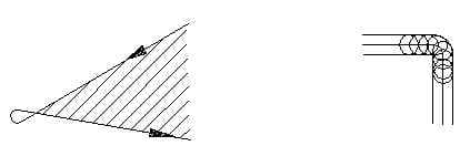
Use the turning round holes into corners method to process sharp corners, and the cutting along arcs method to process obtuse angles.
Cutting sharp corners on thin sheets using the method of turning round holes into corners is recommended for high-speed cutting.
It has the following benefits:
When cutting sharp corners on thick plates, using the method of turning round holes into corners can cause overheating around the sharp corner.
In this case, the “Critical angle, dwell time” parameters should be used for cutting. The machine moves to the sharp corner, pauses for a specific time, and then continues with the turning motion.
LASER processing characteristics:
1. LASER processing parameters:
1)Flat processing range:
LASER processing range XY (25001250), (the maximum size of the existing sheet material is 1220mm*2440mm, and 10mm should be left on the edge of the sheet material during cutting).
2)Processing height:
The LASER head can be lifted by 60-80mm in the vertical direction (Z direction). Therefore, the maximum height of the cutting workpiece without removing the fixtures is 60mm. If the workpiece height exceeds 60mm, it should be lowered, such as by removing the fixtures or using connecting jigs.
3)Processing thickness:
2512 model processing material thickness:
| Machine models | SUS | SPHC | AL | CU |
| 1800W | 5mm | 10mm | 3.0mm | Thin sheet |
| 3000W | 10mm | 25mm | 5mm | 5mm |
LASER can also process materials such as wood panels, acrylic sheets, and metal materials with thin films attached.
Note: For metal cutting, LASER machines have automatic sensing capabilities, but they cannot sense non-metallic materials.
Therefore, the cutting must be set at a specific height during processing.
Additionally, LASER machines have the ability to cut through the thin film before cutting the metal material repeatedly, without the need for height adjustments.
4)Minimum processing slot width and aperture
The minimum processing slot width in LASER cutting is determined by the laser beam diameter, which is usually 0.2mm. Therefore, the minimum processing slot width is 0.2mm, which is a direct cutting line.
Similarly, the minimum processing aperture is determined by the laser beam diameter, which is 0.7mm.
2. Common LASER processing methods
1)One-time LASER cutting:
The complete external and internal holes of the workpiece are cut in one go. This is the most common LASER processing method.
Since there are no restrictions on the cutting workpiece, the laser beam has unlimited contour cutting capabilities, making LASER ideal for processing complex-shaped workpieces.
When all the external and internal holes of the workpiece can be cut out in one go without affecting subsequent workstations and ensuring product quality, one-time LASER cutting is used in engineering scheduling.
2)Secondary processing:
The definition of secondary processing is that due to process requirements or design changes, it is necessary to perform supplementary cutting processing on finished or semi-finished products, by cutting the external and internal holes of the workpiece completely in multiple stages.
When one-time LASER cutting affects subsequent workstations and it is difficult to ensure product quality, a portion of the graphics is cut during the first cutting of the workpiece, and then after being processed by the relevant workstations, a second LASER cutting is performed to cut out the external and internal holes of the workpiece completely.
The product is then processed by subsequent workstations to meet the product’s quality requirements.
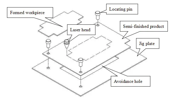
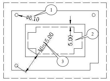
The basic processing principle for secondary processing is shown in Table 3, and the processing steps are as follows:
First, place a fixture plate on the machine and secure it (the size of the plate is not required and can be selected on-site according to actual needs, slightly larger than the workpiece is sufficient because we only need its positioning holes).
Then call the fixture program to cut three positioning holes and the cutting path avoidance holes on the fixture plate. Next, place the workpiece to be cut and use the three positioning pins on the workpiece to position it with the fixture plate.
Finally, call the main program to cut the workpiece. After one piece is processed, remove the positioning pins, take out the workpiece and the cut waste frame, and then process the next batch.
Notes for secondary processing:
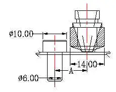
In addition to borrowing existing holes on the workpiece for positioning, the diameter of the positioning pin holes should be uniformly set to 6.10 to adapt to the use of positioning pins with a diameter of 6.00 (as shown in circle 1 in Table 4).
If it is necessary to use positioning holes of other specifications, the LASER on-site personnel should be notified so that they can prepare the corresponding positioning pins. Commonly used positioning pins are shown in the table below:
| Specifications(D) | Spacing | Schematic diagram |
| Φ3.0~Φ8.0 | 0.1mm | 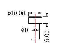 |
The avoidance holes on the fixture plate should be at least 3-5mm larger than the workpiece to avoid LASER flame and prevent the back of the workpiece from becoming burnt (as shown in circle 2 in Table 4).
The distance between the positioning pin holes and the cutting path should be at least 15mm to prevent interference between the LASER head and the positioning pins (as shown in circle 3 in Table 4 and dimension A in Table 5).
3)Etching
LASER has the ability to etch, for example, to etch text or patterns onto a workpiece. The etching depth is related to the processing parameters and is generally around 0.1mm.
Therefore, when the workpiece has surface treatment (such as paint), it will be covered and etching should not be used.
Also note that etching can only be done on the front of the workpiece relative to its placement since the LASER head is on the front and cannot process the backside.
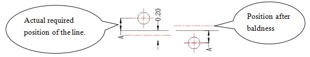
4)Cutting lines
When the workpiece does not require wide slots, cutting lines are necessary. Note that the minimum width for LASER cutting lines is 0.2mm.
During normal cutting, the program will automatically compensate for this difference for features like holes. However, for cutting lines, the program cannot determine which side to compensate for.
If there are strict requirements for cutting line positions, the programming team must be notified and informed which side to compensate for.
For example, different compensation methods must be taken to ensure dimension A as shown in the following diagram:
3. Common Processing Techniques
1)Interference between cutting head and secondary processed parts
Commonly used cutting head diagram:

Note: The interference range of secondary processed parts can be seen from the above cutting head structural dimension diagram.
Interference processing range (different nozzle heads).
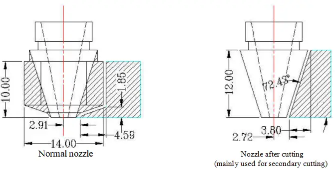
Note: The shaded area outside the nozzle is the normal non-interference processing range.
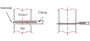
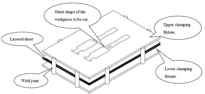
2)Processing of thin materials (thickness less than or equal to 0.2mm):
Laser processing is completed using high-pressure gas and relies on the support of a slat (made of iron).
During the cutting process, the material will be blown down by high-pressure gas and deformed, and the workpiece will be burnt black when passing through the slat.
During the processing, a parent plate is usually cut first to avoid the cutting path of the workpiece, and then the material is placed on the parent plate or on a special support (fixture) and pulled taut to avoid contact with the slat.
The usual practice is to make a pressure tool, clamp the workpiece between the lower pad plate and the pressure tool, and tighten it to achieve the cutting of thin sheet materials.
The following diagram shows this:
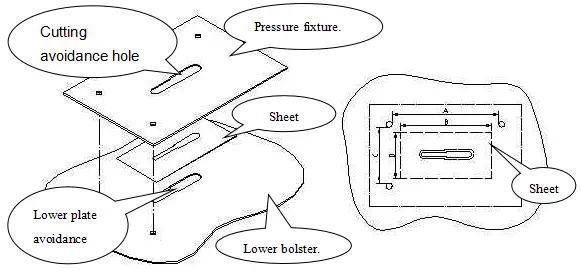
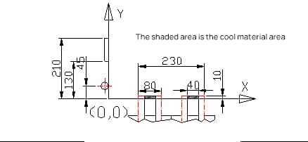
Note: When designing the lower pad plate and pressure tool, the size of the positioning pin hole relative to the two hole edges should be larger than the outline of the thin material.
As shown in Figure 7, dimension A is larger than dimension B, and dimension C is larger than dimension D. Since most thin materials are supplied in the form of coils, before using LASER to cut them, they need to be cut into sheet materials with scissors or a cutting machine.
At this time, the accuracy of the outline size cannot be guaranteed. In this case, a larger distance between the positioning pin holes can ensure that the thin material can still be clamped.
For example, when the actual cutting size D in Table 7 is larger than C, since A is larger than B, the sheet can still pass through the gap between the two positioning pins in the longitudinal direction without interfering with them.
3)Cutting position
The pitch between slats on the worktable is 50mm. When there is interference during secondary processing, the interfering slat can be removed.
When processing small workpieces, if the width of the workpiece in the X direction is less than 50, the workpiece will fall into the waste bin through the gap between the slats after cutting.
If the width of the workpiece in the X direction is between 50 and 100 and only supported by one slat after cutting, it will also fall into the waste bin.
If the size of the workpiece in the X direction is greater than 100, the slat can support the workpiece, and the workpiece can be taken directly from the worktable. See the diagram below:
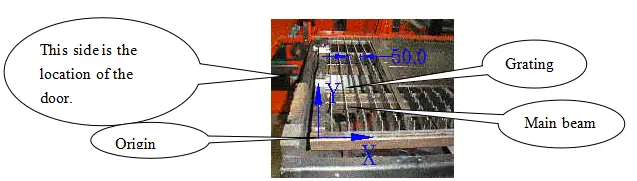
4)Workpiece placement on the machine
The definition of X and Y directions on the LASER machine can be seen in the diagram above, with the X direction along the length of the machine.
The significance of differentiating between the X and Y directions is as follows:
Optimize nesting to achieve the highest material utilization
For secondary cutting of workpieces, align the long edge as parallel as possible to the operator’s position (where the door is opened) for ease of loading and unloading.
Note that the X and Y directions of the workpiece placement on the machine correspond to those in AUTOCAD drawing, unless there is a rotation during the conversion process.
Therefore, in the drawing process, try to place the graphics consistent with the actual requirements.
For example, in general secondary cutting work, you should place the workpiece vertically in the drawing.
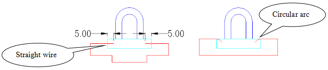
5)Cutting of non-enclosed shapes and inner holes
For the cutting of non-enclosed shapes and inner holes (which is more common in secondary cutting), the starting point should not be placed directly on the workpiece.
Instead, a lead-in should be reserved to prevent the LASER from burning the workpiece when starting the piercing process at the starting point. Generally, a 5mm external lead-in is sufficient.
There are two types of lead-ins according to specific circumstances: straight lead-ins or arc lead-ins. See the application in the following diagram:
6)Reverse rounding
For all workpieces, sharp corners must be reverse rounded to R0.5mm during LASER processing, unless otherwise specified. There are two reasons for this:
Firstly, to prevent sharp corners from causing injury to personnel;
Secondly, to ensure smooth machine movement and avoid burning caused by stopping at corners.
7)Other processing considerations:
When cutting bottom holes in metal parts, the diameter must be increased by 0.05mm because there will be a small connection point at the start and end points of the cutting.
For example, a bottom hole with a diameter of Φ5.4 should be cut to Φ5.45.
The width of the process hole during cutting is generally greater than 0.5mm, and the smaller the width, the more obvious the burrs.
When performing secondary cutting from a flat surface to a convex surface, the speed must be slow, similar to cutting equally thick materials.
LASER is a thermal processing method, and cutting mesh holes and thin materials is affected by heat and may cause deformation of the workpiece.

1. NCT Machining Principle
NCT, or Numerical Control Machine Tool, is a flexible automated machine tool that can adapt to frequent changes in product design.
The various operations and steps required during the machining process, as well as the relative displacement between the tool and the workpiece, are represented by digital codes.
The digital information is sent into a dedicated or general-purpose computer through a control medium (such as paper tape or disk), and the computer processes and calculates the input information, issues various commands to control the machine’s servo system or other executing components, to automatically machine the required workpiece or product.
2. Main Structure of NCT
(1) NC Control System: This system issues most of the control instructions and receives information from various parts of the machine, which is then processed centrally to control the various machining processes of the machine.
(2) Hydraulic System: Provides the power required for punching by the punching head under the support of the NC control system and executes T commands and m parameters.
(3) Cooling System: Takes away the heat generated by the various main parts of the machine during operation to keep the machine stable.
(4) Worktable: Holds the sheet metal and is controlled by a servo motor to feed the XY axis, matching the position of the sheet metal with the punching head, and is the main site of machining.
3. Types of NCT Machine Tools
Currently, there are two major types of machine tools: AMADA machine tools (VIP255, VIP2510, and VIP357) and Trumpf machine tools (TP2000).
Since there are a large number of AMADA machine tools on site, the following discussion will mainly focus on AMADA, with separate explanations for different parts of the Trumpf machine.
4. Tool Disc and Tools.
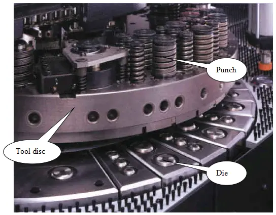
The situation of the tool disc: The tool disc varies depending on the machine model.
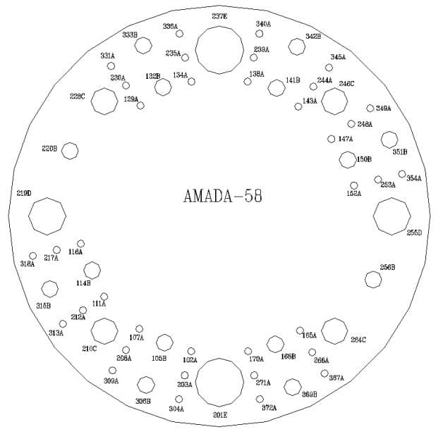
The VIP357 machine has a three-layer turntable with 58 tool positions, divided into five levels (A, B, C, D, E) and two B-type automatic corner turning tool positions (T220, T256).
Except for the A-type tool positions in the middle and inner layers, all others are key tool positions.
The VIP255 and VIP2510 machines have a two-layer turntable with 31 tool positions, divided into four levels (A, B, C, D) and three automatic corner turning tool positions (two B-type: T210, T227 and one C-type: T228).
Except for the A-type tool positions in the inner layer, all others are key tool positions. During the tool arranging process, it is recommended to avoid arranging tools in the rotating tool positions.
Also, it is important to note whether the tool position is a key position or not. Round-shaped tools such as round knives, salad knives, punching tools, stamping tools, circular convex points (bumps), etc. can be placed in non-key tool positions, while other tools must be placed in key tool positions.
Tool status:
The NCT tools are divided into five levels A, B, C, D, and E according to the size of their external dimensions, with level A having the smallest external dimensions and level E having the largest. The tools of each level correspond to the tool positions on the tool disc.
The specifications for the installation of molds on the tool disc tool positions are listed in the table below:
| Type of Mold | Nominal Size | Standard Upper Mold Size | Model Number |
| A | 1/2″ | 1.6-12.7mm dia(0.063″-0.5″dia) | 36 (12) outer ring with 12 supports and KEY |
| B | 1-1/4″ | 12.8-31.7mm dia(0.501″-1.25″dia) | 14 (14) outer ring with 6 supports and 4 KEY8 supports with 2 KEY for inner ring. |
| C | 2″ | 31.8-50.8mm dia(1.251″-2″dia) | 4(4) |
| D | 3-1/2″ | 50.9-88.9mm dia(2.001″-3.5″dia) | 2(2) |
| E | 4-1/2″ | 89.0-114.3mm dia(3.501″-4.5″dia) | 2(2) |
※ The number inside the parentheses indicates the applicable mold model.
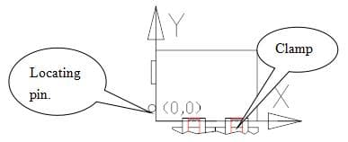
1. The definitions of X and Y directions are as follows:
The X direction is parallel to the two jaws, and the Y direction is parallel to the locating pin or locating column. See the diagram below:
2. Machining range:
| Model number | X direction | Y direction |
| VIP357 | -10<x<1840 | -50<y<1270 |
| VIP255 | -10<x<1210 | -50<y<1270 |
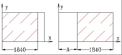
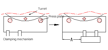
If the X direction exceeds this range, the automatic claw movement command G27 can be used to adjust it. The format is G27 X movement amount.
The diagram below shows the before and after using the automatic claw movement method. The dashed lines in the diagram are two cylindrical pressure plates used to fix the sheet metal when the jaws are released to prevent movement.
After the jaws are released and retracted outward, they move towards the positive X-axis direction by Amm, then move inward to the corresponding position and clamp. This completes the entire claw movement process.
The machining range before and after the claw movement is expanded as shown in the diagram below.
If the Y direction exceeds this range, it may pose a danger because it means that the jaws may have entered the danger zone, as shown in the diagram below.
In the first scenario, the jaws are located between the upper and lower dies, and punching may damage the jaws.
In the second scenario, although the jaws will not be damaged, the material may deform due to being located on different planes.
The solution is to change the position of the jaws, change the position of the die, change the size of the die, or design alternative jaws.
3. Workpiece positioning
The positioning of the workpiece on the NCT is achieved by the jaws and the locating pin or square locating block in the Y direction.
Positioning the workpiece against the jaws determines the position in the Y direction, and positioning against the locating pin or square locating block determines the position in the X direction.
The distance from the origin positioning position to the locating pin or square locating block is as follows:
| Model number | Distance from the origin positioning position |
| VIP357 | Locating pin: 45mmLocating block: 130~210mm. |
| VIP255 | Locating pin: 59mm |
4. Jaw-related data
The relative position of the two jaws in the X direction on the NCT can be adjusted to accommodate different sizes of sheet metal.
However, the two jaws cannot be brought infinitely close to each other; there is a minimum distance between them, as shown in the diagram below. If the workpiece is smaller than this minimum value, it can only be clamped by one jaw.
5. List of danger zones and forming interference zones for each tool type’s jaws
During the movement of the workpiece held by the jaws, it is possible for the jaws to be punched, resulting in damage.
Therefore, a certain safe distance must be left between the processing section and the jaws.
The minimum distance from the jaws in the Y direction = upper die radius + jaw width + deformation zone.
| Project | Lower die diameter mm | Upper die diameter mm | Minimum distance from the jaws in the Y direction mm | ||
| Tool type | |||||
| A | 18 | 25.4 | 25.4 | 30 | |
| B | 38 | 47.8 | 47.8 | 40 | |
| C | 74 | 89 | 70 | 50 | |
| D | 110 | 125.4 | 110 | 80 | |
| E | 133 | 158 | 133 | 95 | |
Note:
1) The deformation zone of the material is usually taken as 5mm, and the specific value depends on the thickness of the material and the forming height. This value is for reference only.
2) The jaw width is taken as 10mm.
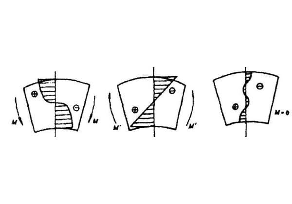
The forming interference zone in the upward direction = upper die radius + deformation zone
(Note: deformation zone = forming element radius or width/2 + material deformation zone)
| A | B | C | D | E | |
| Minimum machining interference zone mm | 12.7+Deformation zone | 24+Deformation zone | 35+Deformation zone | 55+Deformation zone | 67+Deformation zone |
The forming interference zone in the downward direction = lower die radius + deformation zone
(Note: deformation zone = forming element radius or width/2 + material deformation zone)
| A | B | C | D | E | |
| Minimum machining interference zone mm | 12.7+Deformation zone | 24+Deformation zone | 45+Deformation zone | 63+Deformation zone | 79+Deformation zone |
6. Estimated processing time for NCT
Tool changing time
Adjacent tool position: approximately 1.5 seconds
Interval tool position: approximately 2.0 seconds
Rotary tool position: approximately 2.5 seconds
The above tool changing times can be unified to approximately 2.0 seconds because even for a complex workpiece with 30 installed tools, the error in tool changing time should not exceed 15 seconds.
Punching frequency
For single-hole tools, the maximum punching frequency is 8 per second, with a hole distance of 4-5mm, i.e., 480 per minute. However, according to the tool and equipment conditions on site, the punching frequency is generally 4 per second, i.e., 240 per minute.
For multi-hole tools, the maximum punching frequency is 2 per second, i.e., 120 per minute. However, according to the tool and equipment conditions on site, the punching frequency is generally 60-70 per minute.
Forming time
7. Typical machine tool characteristic parameters.
Technical performance table for VIPROS-357 processing:
| Project | Content | |
| Maximum processing size. | Without using automatic tool changing | -10<x<1840 -50<y<1270 |
| Using automatic tool changing | 1270<x<2440 | |
| Maximum processing thickness (mm) | 6 | |
| Maximum load capacity (kg) | 100 | |
| Processing accuracy (mm) | ±0.10 | |
| Worktable movement speed (X, Y m/min) | 65、50 | |
| Rotary turning speed (rpm) | 30 | |
| Maximum punching frequency | 520/420 (stroke 3mm, pitch 2mm)360/360 (stroke 6mm, pitch 2mm)275/275 (stroke 8mm, pitch 8mm)275/240 (stroke 8mm, pitch 25.4mm) | |
| Straight-line distance between two positioning pins and the jaws | Block: 130.00 Round locating pin: 55.00 | |
| Width of one jaw (mm) | 80 | |
| Minimum width when two jaws are combined (mm) | 220 | |
| Minimum air pressure (kg/cm2) | 3 | |
| Minimum oil pressure (kg/cm2) | 190 | |
| Maximum oil temperature (℃) | 700 | |
List of processing parameters for Trumpf machines
| Scope of application | It is suitable for small-batch and simple workpieces and is mainly used for secondary processing of workpieces with dense mesh holes. | |
| Processing thickness | The maximum processing thickness is 6.4 mm | |
| Tool turret | The TP2000 machine has a total of 11 optional tool positions. After deducting the two positions occupied by the clamps, a program can use up to 9 tool holders at a time, which means a maximum of 9 ordinary tools can be used in one program. (Here, ordinary tools refer to tools that can only hold one tool on a tool disk, as opposed to multi-tool tools.) If multi-tool tools are used, up to 90 tools can be installed at a time. If more than 9 tool holders are needed for processing, the actual processing can be achieved by stopping the machine halfway through and changing the tool. In this case, the operator will first install the first 9 tools on the tool holders, and when the program reaches the 10th tool, the machine will stop and the tool will be changed before continuing with the program to complete the processing. | |
| Positioning method | Positioning pillars are used for positioning. There are two positioning pillars with a diameter of 20mm and a Y-axis distance of 90mm. The applicable range for the two positioning pillars is as follows: Positioning pillar 2 is suitable for secondary processing of workpieces with graphic elements that are a maximum distance of less than 530mm from pillar X direction and with smaller dimensions (X < 1220). Positioning pillar 1 is suitable for all other cases except for those mentioned above. The distance between the two positioning pillars is 940mm. | |
| Machine working range | Without additional platform: 1275x1280mm. With additional platform: 1275x2030mm. | Note: When using a multi-position tool, the machining range is correspondingly reduced. For a 5-position tool, it is reduced by 20mm, and for a 10-position tool, it is reduced by 26mm. |
| Actual machining range | X direction: -25 to 1275mm. Y direction: -7 to 1280mm. When changing tools, Ymax = -161.5mm. | |
| Danger zone of the clamp. | Regular tool: Xmax = 97×2 = 194mm, Ymax = 72mm.5-position tool: Xmax = 97×2 + 20×2 = 234mm, Ymax = 72 + 20 = 92mm. 10-position tool: Xmax = 97×2 + 26×2 = 246mm, Ymax = 72 + 26 = 98mm. | |
| Automatic unloading size. | 200X200mm. | |
| Machining speed. | X-axis motion speed: 90m/min. Y-axis motion speed: 60m/min. Combined speed of X and Y axes: 108m/min. Impact speed: at positioning height of 1mm: 900 beats/min, at positioning height of 25mm: 420 beats/min. Marking speed: 2200 beats/min.C-axis rotation speed: 3 rotations/s. | |
| Maximum punching diameter | Single stroke 76mm Standard multicut 200mm | |
| Accuracy | Positioning accuracy 0.1mm Repeatability 0.03mm | |
There are various ways of NCT processing, such as punching mesh holes, step punching, nibbling, chamfering, automatic clamp movement, etc.
Each processing method corresponds to specific NC program instructions. Using the appropriate instruction not only makes processing easier and less prone to errors, but also improves efficiency. This section will provide some explanations for these typical NCT processing methods.
1) Punching Mesh Holes
In practical processing, NCT often processes a large number of heat dissipation mesh holes.
G36 mode has the fastest processing speed when punching mesh holes.
If the mesh holes within a unit area exceed 25%, punching will cause material deformation. In this case, appropriate process treatment is necessary.
Usually, the entire sheet material will be punched first with NCT, and after the workpiece is punched, the sheet will be flattened.
If there are critical dimensions that need to be guaranteed, consider secondary processing after flattening.
When the size and spacing of mesh holes are inconsistent, consult with the customer to make them consistent within the tolerance range, in order to facilitate subsequent mass production mold opening (such as NCT opening multiple head punching).
2) Continuous Punching (Rectangular) Holes
In NCT processing, there are often cases of punching large rectangular holes, which can be processed by continuous punching with small rectangular molds.
3) Nibbling
In the absence of a laser cutting machine, nibbling may be used to process a larger sized circular ring or straight length.
4) Chamfering
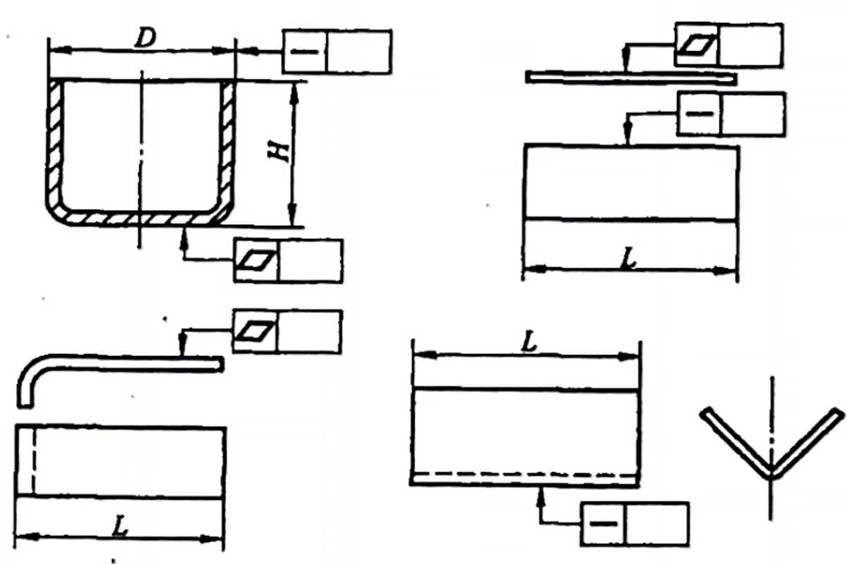
5) Machining of Salad Holes
As the formation of Salad Holes is achieved by extrusion, it causes deformation of the material after punching.
(1) Range of material filling for Salad Holes:
For the center position less than 10mm away from the edge, it should be filled with material.
For distances greater than 15mm from the edge, no material should be filled.
For distances between 10-15mm, it should be determined based on the actual situation of the Salad Hole whether to fill material or not.
When punching two Salad Holes, if the distance between the two larger circles is greater than 5mm, they will not affect each other. If it is less than 5mm, an additional punching is necessary to reduce deformation.
(2) Method of filling material for Salad Holes:
With the aim of improving processing speed and ensuring quality (reducing joints),
for a single Salad Hole, fill material with a diameter as the basis, offsetting each side by 5mm, which is the longer side (assuming this length is A). The other side should be A/2+1, and a square blade punch of SQA+1 should be selected.
For filling material for two or more Salad Holes together, fill with a width of 10mm, the length depending on the actual situation.
(3) Selection of pre-hole size for Salad Holes:
In general, the pre-hole size is selected according to the following principles:
90° Salad Hole Φpre = Φbottom hole of the formed shape + 0.2&0.3
100° Salad Hole Φpre = Φbottom hole of the formed shape + 0.3&0.5
120° Salad Hole Φpre = Φbottom hole of the formed shape + 0.5&0.6
140° Salad Hole Φpre = Φbottom hole of the formed shape + 0.7&0.8
The forming depth of NCT-punched Salad Holes is generally not greater than 85% (T<2.5mm).
6) Press Line Treatment
The depth of NCT press lines is 0.4T.
When using a 150.5 press line tool, if it is less than 20mm away from the edge, it needs to be filled with material. When using a 150.2 press line tool, if it is less than 15mm away from the edge, it needs to be filled with material.
The method of filling material is similar to that of Salad Holes.
Press lines can be targeted or pressed along the entire bending line. If only one side of the bending line is pressed and the other side is not, it is prone to bending and size discrepancies.
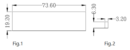
7) Character Mold Cutter
Reverse character mold cutter:
Figure 1 shows the groove size of the reverse character mold cutter, and Figure 2 shows the size of one character mold. It can be seen that the reverse character mold cutter can hold up to 3 rows and a maximum of 23 character molds per row.
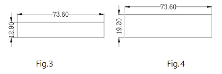
Front-facing character mold cutter:
The front-facing character mold cutter has two types of grooves, as shown in Figures 3 and 4. The length direction is the same, but the width direction differs by the width of one character mold.
Therefore, in the operation, corresponding processing can be made according to the actual situation.
The following are the actual measurement sizes of several character molds, for reference in engineering layout.
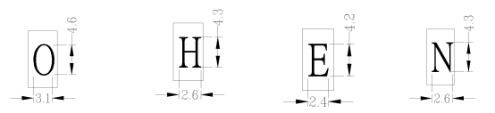
Each character mold has a character height of 0.6mm.
Therefore, the maximum depth that can be achieved by embossing is no more than 0.6mm. If strict requirements are needed for the flatness of the workpiece, special attention should be paid to ensuring that the depth of the embossing is not too deep.
8) Punching
Punching requires special tools, and the most commonly used punching tool is the one used for M3 buds (punching hole diameter 2.60).
The minimum distance from the edge for NCT punching is 3T, the minimum distance between two punching holes is 6T, and the minimum safe distance from the bending edge (inside) of the punching hole is 3T+R.
If it is too small, press line processing is required. (T represents the thickness of the material).
9) Tapping bottom hole
Direct tapping will cause burrs, so a small Salad Hole is punched on both sides of the tapping hole to avoid this phenomenon.
Additionally, Salad Holes can also guide the threading process. The specification for Salad Holes is generally a depth of 0.3mm and an angle of 90 degrees.
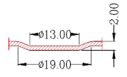
10) Drawing or Punching Convex Features:
There are two ways to process convex features with NCT:
Develop dedicated convex feature tools.
Use ordinary tools, which can achieve drawing or punching convex features through the M command, but can only be oriented downward.
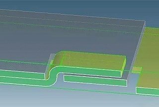
As shown in the figure below: using the upper mold of RO13 and the lower mold of RO19 can punch out this convex feature. The same method can also be used for half-cutting and convex points.
When using this method, pay attention to two points: (1) there must be available upper and lower molds, and (2) the forming depth cannot exceed one material thickness.
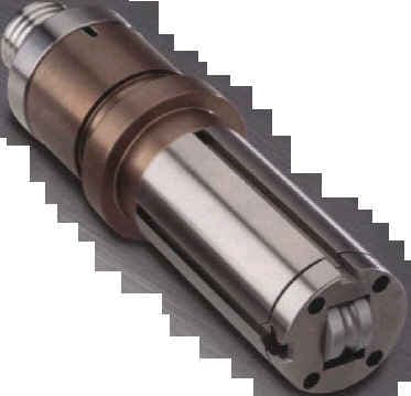
11) Flanging
Working principle of rolling cutting tools:
When using WILSON rolling cutting tools to process reinforced ribs or other workpieces, the upper and lower molds of the rolling cutting tools are used to press the workpiece, and then the workpiece is moved according to the shape of the processing drawing by the clamps, thereby completing the processing of such elements.
Structure of rolling cutting tools:
1. Structure of lower mold: The lower mold of the rolling cutting tool consists of a lower mold base and a roller assembly (for rolling cutting tools used for rolling cutting, there is also a control wheel). The roller includes bearings and can rotate freely. Taking the rolling cutting tool for reinforced ribs as an example, only the lower mold of the rolling cutting tool is introduced. The lower mold base plays the role of supporting the roller.
2. Structure of upper mold: The upper mold of the rolling cutting tool consists of an upper mold base and a roller assembly. Taking the rolling cutting tool for reinforced ribs as an example, the upper mold of the rolling cutting tool is shown in the figure below:
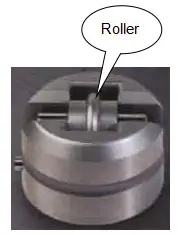
The existing WILSON rolling tools have unlimited thickness for processing, and the total height of the reinforced rib (including two material thicknesses) is (2.3+T)mm.
1. Anti-misoperation
For asymmetric workpieces that are difficult to distinguish direction or have left-right symmetry, foolproofing measures must be taken to prevent the workpiece from being installed incorrectly during the secondary NCT processing. The following are commonly used methods:
1) Using the photoelectric sensing installed in NCT.
2) Using material addition:
Adding a small piece of material on one side of the Y axis according to the actual situation, with a size slightly smaller than the tool (usually SQ10~15) used to cut this material.
The position is roughly opposite to the positioning pin or block, and then cut with a square tool.
The left figure below shows an example:
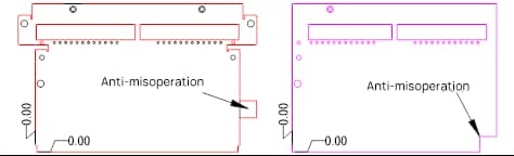
If the workpiece needs to undergo other secondary processing to form its shape after being cut by NCT, foolproofing corners can be used.
As shown in the right figure above, the size of the foolproofing corner is usually taken as 10X10 to allow for punching with a SQ10 square tool.
2. Processing for hole distance less than material thickness from the edge
Punching square holes can cause the edge to flip up, and the larger the square hole, the more obvious the edge flipping.
At this time, secondary LASER cutting is often considered (customer opinions can also be sought to determine if this deformation is acceptable).
Note: The distance between holes and edges or between holes should not be too small in NCT stamping, and the allowable values are shown in the table below:
| Material | Punching round holes | Punching square holes |
| Hard steel | 0.5t | 0.4t |
| Soft steel and brass | 0.35t | 0.3t |
| Aluminum | 0.3t | 0.28t |
The minimum hole diameter for NCT stamping
| Material | Punching round holes | Punching square holes |
| Hard steel | 1.3T | 1.0T |
| Soft steel and brass | 1.0T | 0.7T |
| Aluminum | 0.8T | 0.6T |
Clearance between upper and lower dies for NCT punching of different materials:
| Plate thickness (t) | Clearance between upper and lower dies for different materials | ||
| Steel plate | Aluminum plate | Stainless Steel plate | |
| 0.6~1.0 | 0.15 | 0.15 | 0.2 |
| 1.0~1.5 | 0.2 | 0.15 | 0.25 |
| 1.5~2.0 | 0.25 | 0.2 | 0.3 |
| 2.0~2.5 | 0.3 | 0.25 | 0.4 |
| 2.5~3.0 | 0.4 | 0.3 | 0.5 |
From the table above, it can be seen that the greater the thickness of the material, the larger the clearance between the upper and lower dies used.
Currently, the clearance used for the molds at the sample center is basically 0.2mm, except for a small amount of shearing blades that have 0.3mm.
Therefore, if materials above 2.0mm thickness are to be processed using NCT, it is necessary to consider reworking the molds.
3. Relationship between Material Properties and NCT Processing
The material properties that affect NCT processing are material ductility and material hardness.
Generally, moderate hardness and ductility are beneficial for punching and cutting processing. Excessive hardness will increase punching force and have a negative impact on punching head and precision. Too low hardness will cause serious deformation during punching and greatly limit precision.
Material plasticity is opposed to hardness, where high hardness leads to low plasticity, and low hardness leads to high plasticity.
High plasticity is beneficial for forming processing, but not suitable for nibbling, continuous punching, punching holes, and shearing. Low plasticity can improve processing accuracy, but punching force will increase.
However, as long as it is not excessively low, the impact is not significant.
Ductility plays a significant role in the rebound during processing. Appropriate ductility is beneficial for punching and can suppress the degree of deformation during punching.
However, if the ductility is too high, rebound after punching will be severe, which will negatively affect the precision.
4. Limitations of NCT Processing
When the distance from the clamp is less than 90mm, the punching speed of NCT slows down as the distance decreases (for VIP357).
NCT punching is a back-and-forth movement of the workpiece on the tool turret.
Therefore, in general, the reverse side of the workpiece cannot have protrusions unless they are small bumps of unimportant size and low height. Half-shear points are easily deformed or detached during material movement.
Alternatively, the workpiece can be moved to a brush after punching in one place and then processed further.
When NCT processing strengthening ribs, the step distance is about 1mm, so the punching speed is very slow and not suitable for mass production.
The minimum width of the process slot opened by NCT processing is 1.2mm.
The tool used for NCT punching must be larger than the material thickness. For example, a tool with a RO1.5 radius cannot punch a 1.6mm material.
Materials below 0.6mm thickness are generally not processed using NCT.
Stainless steel materials are generally not processed using NCT. (Of course, materials between 0.6-1.5mm can be processed using NCT, but tool wear is high and the probability of waste products on-site is much higher than other materials such as GI.)
Note that the machine only has three D-shaped rotary tool positions.
Since aluminum is relatively soft, a slightly larger clearance between the upper and lower dies can easily cause burrs, especially when punching mesh holes. (Solution: reduce the clearance between the upper and lower dies).
According to on-site testing, the height of half-shear points punched by NCT should not exceed 0.6T. If it exceeds 0.6T, it is prone to detachment.
When NCT tools are required to cut outer shapes or internal holes with rounded corners, the corner radius of the outer shape and internal hole should be R≧0.5T.
NCT can be used for direct material feeding and opening NCT blanking molds for mass production of small workpieces (limited to SQ80 and RO113).
5. Advantages and Disadvantages of NCT and Laser Processing
(1) Laser cutting speed for straight lines is faster than NCT.
(2) Laser cutting can handle irregular curves.
(3) Laser cutting speed for punching holes is slower than NCT. The fastest speed for laser flying cutting is about 100 pieces/min, while the punching speed of NCT exceeds 400 pieces/min.
(4) The cutting surface of the laser is smooth and delicate, while NCT step punching leaves joints (the step distance of NCT’s jointless tools is relatively small, and the length of the D-shaped tool is only 25mm).
(5) NCT punching only requires converting the workpiece elements to be processed into NCT CAM and inputting the converted program code into the NCT punching machine, which can use existing shared molds for punching and cutting at high speed and efficiency. It is suitable for cutting regular outer shapes and internal holes and processing other forming surfaces in batch production.
(6) Laser cutting is suitable for cutting outer shapes, while NCT is suitable for punching holes. If there are no existing NCT tools, NCT tools should be developed based on the actual situation.
1. Scope of Application:
Currently, the shearing machine is mainly used for rough cutting of sheet metal, providing sheet materials for subsequent processing in NCT or laser machines. It can also be used for direct shaping of workpieces with low accuracy requirements.
2. Processing Accuracy: +/-0.1mm
3. Modes:
According to current operations, there are three ways to shear plates:
For simple-shaped workpieces with low accuracy requirements, the shearing machine can be used for direct material feeding. However, this method should be used with caution.
The shearing machine is used to cut small sheet materials before processing with NCT. This method is equivalent to secondary processing of the workpiece in NCT. Please refer to NCT for precautions.
NCT is used to process the entire sheet first without cutting the workpiece shape, and then the entire sheet is moved to the shearing machine to cut it to the required external dimensions.
The process card specifies shearing machine material feeding without providing engineering drawings, but detailed specifications and plate dimensions must be clearly written and rounded to the nearest decimal or integer, as required.
Other graphic elements and three-positioning pin holes are processed in NCT.
4. Processing Characteristics:
For NCT, the biggest advantage is saving time on cutting external shapes, because the external shape is not very important for secondary processing, and it is generally positioned through three positioning pin holes.
So far, the shearing machine has not been able to solve the problem of surface scratches on sheet metal. There is a hidden risk of surface scratches when using the shearing machine for material feeding.
However, it does not have a significant impact on small-scale sampling.
1. Scope of Application:
Wire cutting can be considered for material feeding when the workpiece is thin and only requires cutting external shapes or fewer internal holes.
2. Basic Steps:

As the founder of MachineMFG, I have dedicated over a decade of my career to the metalworking industry. My extensive experience has allowed me to become an expert in the fields of sheet metal fabrication, machining, mechanical engineering, and machine tools for metals. I am constantly thinking, reading, and writing about these subjects, constantly striving to stay at the forefront of my field. Let my knowledge and expertise be an asset to your business.