Aluminum Heat Treatment: Your Comprehensive Guide
Ever wondered how aluminum transforms from a raw metal into the sturdy, versatile material we rely on daily? This article unveils the fascinating heat treatment processes behind aluminum and its…
Imagine investing time and resources into manufacturing precision gear rings, only to find them distorted after heat treatment. Why does this happen, and how can it be controlled? This article explores the causes of gear ring distortion during heat treatment and provides strategies for minimizing these issues. By understanding the interplay between different processing methods, readers will learn practical techniques to enhance the accuracy, reduce defects, and extend the service life of gear rings. Dive in to discover how to achieve optimal results in gear ring manufacturing.
The significant disparity between the diameter and width/height of a gear ring can cause issues during heat treatment, leading to deviations in the roundness of the inner hole, flatness of the end face, and taper distortion.
Heat treatment-related distortion is a prevalent issue in the heat treatment process of gear rings.
The machining process of gear rings is complex and results in a low qualification rate for distortion, large machining allowances, high rates of defective products, high costs, and low accuracy and high noise levels, all of which significantly impact its service life.
To improve the qualification rate and processing accuracy of heat treatment distortion in gear rings, it is necessary to coordinate cold and hot processing, optimize processes, improve clamping and furnace methods, and adopt advanced heat treatment processes and equipment. This will reduce the processing cost of products and minimize the number of defective products.
A large gear ring with dimensions of φ2180mm (outer diameter), φ1750mm (inner diameter), and 550mm (width), made of 17CrNiMo6 steel, has strict requirements for heat treatment distortion. However, after undergoing carburizing and quenching, the tooth top height is often observed to increase by 4 to 5mm, and in some cases, up to 6 to 7mm.
For this, the following control measures are adopted:
(1) Preparation of pretreatment process
The gear ring is subjected to a quenching and tempering process, which involves heating it to 860°C for quenching (20 to 30°C higher than the final quenching temperature) and then tempering at 650°C. The ideal outcome is to control the increase in inner hole diameter within 8 to 10mm.
After undergoing carburizing and cooling, air cooling, temperature equalizing at (820 ± 10)°C, quenching in a 170°C nitrate bath for cooling, and two tempering cycles at 210°C, the diameter of the tooth top circle is only about 2mm larger than before carburizing and quenching, meeting the expected increase. Additionally, the roundness and upper and lower taper of the gear ring meet the requirements.
(2) Process key points
It is crucial to maintain strict control over the quenching temperature during the quenching and tempering process. If the temperature is too low, it will not effectively reduce the large distortion. Conversely, if the temperature is too high, the size of the tooth tip circle after carburizing and quenching may decrease, requiring further testing.
The driven gear ring in a tricycle transmission (refer to Figure 1) is made of 20CrMnTi steel and has strict technical requirements for heat treatment. The deep layer of Carbonitriding should be 0.6 to 1.0mm, with a tooth surface hardness of 58 to 64HRC and a core hardness of 35 to 48HRC. The positional tolerance of the threaded hole and single chain groove must be 0.05mm.
Before charging, 10 M8 screw holes are sealed with an anti-seepage coating. After undergoing Carbonitriding at 850 to 860°C, the gear ring is directly quenched and tempered.
Upon inspection, it was found that the position of the threaded hole and single chain groove were out of tolerance, and the anti-seepage coating was not easily removable.
The improved process and effect are as follows:
(1) Improved process
Gear making and forming → slow cooling after carbonitriding → turning (cutting) the infiltrated layer, broaching (cutting) the keyway, drilling and tapping → heating and quenching at 850 ~ 860 ℃ → low temperature tempering → capping (protecting the threaded hole) shot blasting → grinding (cutting) the spoke plate → inspection.
(2) Improvement effect
Through inspection, the qualified rate of heat treatment distortion of driven gear ring is over 95%.
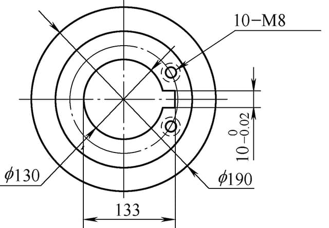
Fig. 1 Schematic diagram of driven gear ring
The gear ring of a mine rolling mill reducer has an overall dimension of φ1631mm (outer diameter), φ1364mm (inner diameter), and 300mm (width), with a single piece weight of 1434kg and a normal modulus of 20mm. It has 78 teeth and is made of 20CrNi2MoA steel, requiring carburizing and quenching.
(1) Technical requirements for modified gear ring
To control and minimize heat treatment distortion of the gear ring, some technical requirements have been revised. The revised technical requirements for the gear ring are listed in Table 1.
Before undergoing carburizing, the gear ring undergoes a quenching and tempering treatment, with a quenching and tempering hardness of 217 to 255HBW. The effective hardened layer should be 3.90 to 5.10mm.
(2) New technology
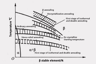
The normalizing process after forging has been changed to a combination of normalizing and high temperature tempering. Additionally, a spheroidizing annealing process has been added after carburizing to guarantee that the size of the carbide particles in the carburizing layer does not exceed 1 μm.
The spheroidizing annealing process is depicted in Figure 2, and the results from both Process A and Process B in Figure 2 are similar.
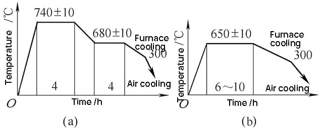
(a) Two stage isothermal spheroidizing annealing
(b) One stage isothermal spheroidizing annealing
Fig. 2 spheroidizing annealing process of 20CrNi2MoA steel gear
New process route: forging → normalizing + high temperature tempering → rough turning → flaw detection → quenching and tempering → fine turning and gear milling → carburizing → spheroidizing annealing → quenching and tempering → shot blasting → fine turning of inner hole and two planes → grinding of inner hole and two planes → gear grinding → keyway → flaw detection → product.
Tooling design: design the upper and lower cover plates to control the distortion of the gear ring. See Fig. 3 for details.
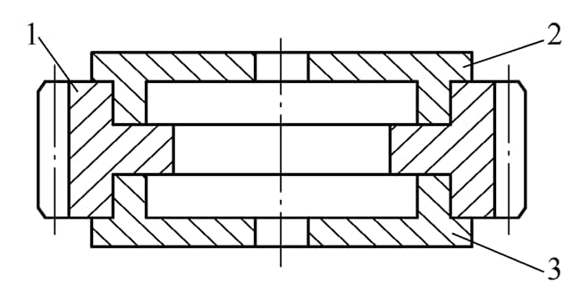
Fig. 3 heat treatment fixture of gear ring
1. Gear ring
2. Upper cover plate
3. Lower cover plate
(3) Inspection results
The surface hardness, core hardness, and effective hardened layer depth of the gear ring meet the technical requirements. The surface of the gear ring has a carbon concentration of 0.76% (by mass) and the carbide particle size has reached 0.5 μm.
The metallographic structure is composed of martensite and retained austenite (grade 2), carbide (grade 1), and core ferrite (grade 2). All mechanical properties indexes meet the technical requirements outlined in the drawings.
Inspection of the gear ring distortion showed that the inner hole roundness is 0.90mm, the tooth tip diameter variation is within the range of +3.1 to +4.0mm, and the normal variation is between +0.2 to +0.6mm, meeting the technical requirements.
Table 1 technical requirements of modified gear ring
| Effective hardened layer depth / mm | Tooth surface hardness (HRC) | Heart hardness (HRC) | Surface carbon concentration of carburized layer (%) | Mechanical properties of heart after heat treatment | ||||
| σb/MPa | σs/MPa | δ5(%) | ψ(%) | αk/J·cm-2 | ||||
| 3.90~5.10 | 58~62 | 30~45 | 0.75~0.95 | ≥1100 | ≥800 | ≥8 | ≥35 | ≥60 |
The ultra-thin internal gear ring in a large transmission gearbox has overall dimensions of φ1120mm (outer diameter), φ944mm (inner diameter), and 260mm (width). It is made of 17CrNiMo6 steel, weighs 550Kg, and requires heat treatment to meet the following technical requirements:
Post heat distortion requirements: taper ≤ 1.35mm, roundness ≤ 1.35mm, common normal line variation ≤ 0.7 ‰, and tooth top circular shrinkage ≤ 1.5 ‰.
(1) Original processing route, process and distortion of gear ring
Original processing route: rough turning of forging stock → drilling → gear shaping → carburizing and quenching → shot peening → fine turning → gear grinding → finished product.
The original carburizing process route is: preheating 650 ℃ × 1h → carburizing (930 ± 10) ℃ × 50h → temperature reduction, thermal insulation 830 ℃ before discharge × 2h → outgoing air cooling → high temperature tempering (680 ℃) × 4h → quenching and heating (820 ± 10) ℃ × 2.5h → salt isothermal quenching (160 ± 10) ℃ → low temperature tempering (210 ± 20) ℃ × 10h → outlet air cooling.
After cleaning the gear ring, apply an anti-seepage coating to 5 pieces per furnace.
The carburizing atmosphere is a gas enriched with methanol and isopropanol.
Upon inspection, it was found that while all other items meet the technical requirements, the gear ring exhibits significant distortion.
(2) Improved process
High-temperature normalizing must be performed after rough machining and before gear ring shaping.
To reduce residual stress and thermal stress and lower the carburizing temperature, the number of step heating stages is increased in the early stage.
Following these improvements, the isothermal temperatures of 400°C and 850°C have been increased, and the quenching temperature has been appropriately reduced.
Inspection has revealed that while the distortion of the gear ring has improved by one grade, there are still occasional cases where it falls outside of tolerance. See Figure 4 for the carburizing process.
The carburizing correction quenching process and gear ring quenching cooling utilize the die correction method. See Figure 4 for the gear ring’s carburizing correction quenching process curve.
The die correction quenching method cools the die and gear ring together, allowing the gear ring to be corrected by the die during the cooling process.
In the subsequent long-term tempering process, the stress generated during quenching and cooling is eliminated, the size of the gear ring is stabilized, and the rebound of distortion is prevented.
The results of the distortion test are ideal.
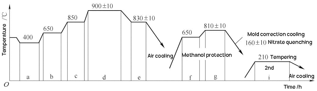
Fig. 4 carburizing correction quenching process curve of large gear ring
The JT001 gear ring in TY320, TY220, D65, and other gearboxes has an outer gear diameter of 318.1mm, an inner gear diameter of 251.7mm, and a width of 51.5mm.
The material used is 42CrMo steel, which has a quenching and tempering hardness of 262 to 302HBW.
After nitriding treatment, a ΔM of less than or equal to 0.10mm is required.
(1) Original heat treatment process and distortion
Blank normalizing (880 ℃× 3h) + tempering after rough turning (salt bath 820 ℃× 0.5h, oil quenching + tempering) + correction + aging treatment after finishing turning (300 ℃× 5h) + gear shaping + ion nitriding (520 ℃) and then cooling with the furnace.
Through inspection, the m value and variation amount are out of tolerance, and the qualified rate of gear ring distortion is only about 70%.
(2) Improved process and effect
The original process of “quenching and tempering before correction and nitriding” was changed to “correction and tempering before nitriding”.
The rate of gear ring distortion meeting the qualifications has increased to more than 98%, and the variation in ΔM value of the gear ring was reduced from a maximum of 0.46mm before the adjustment to 0.10mm after quenching and tempering.
The aging temperature was increased from 300°C to 560°C, which not only ensures the complete release of machining stress, but is also 30 to 50°C higher than the nitriding temperature, thus minimizing the distortion of the nitrided gear ring. The maximum value of ΔM was reduced from 0.22mm before the adjustment to 0.08mm after the adjustment.
The gear ring (see Fig. 5) is made of 40Cr steel.
The technical requirements are: the quenching and tempering hardness is 28 ~ 32HRC, the high-frequency quenching hardness of the gear part is 48 ~ 52HRC, and the gear ring runout is < 0.048mm.
(1) High frequency quenching technology and distortion of gear ring
The electrical parameters for the high-frequency quenching process are as follows: the current frequency is 250kHz, the anode and grid currents are 7 to 7.5A and 1.4 to 1.7A, respectively, the heating time is 30 to 40 seconds, and the cooling water pressure must be greater than or equal to 0.2MPa.
During high-frequency quenching, the cooling speed of the part close to the 30mm hole is fast, while the cooling speed of the part away from the hole is slow.
This uneven cooling speed is the cause of the gear ring runout falling outside of tolerance.
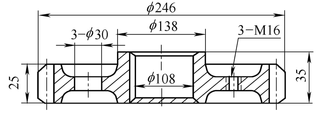
Fig. 5 Schematic diagram of 40Cr steel gear ring
(2) Improve process flow and effect
Improved process flow: forging → rough turning → quenching and tempering → fine turning of outer circle and inner hole → gear hobbing and deburring → gear shaving and deburring → cleaning → high-frequency quenching of tooth part → fine turning of empty tools at both ends → drilling and spot facing → drilling and tapping → single keyway pulling → deburring and sand blasting → cleaning and warehousing.
Improvement effect: after the adjustment of the process flow, the runout of the gear ring after high-frequency quenching is within the tolerance range.
The internal gear ring in the steering mechanism of a heavy-duty dump truck has an outer diameter of φ444mm and an inner diameter of φ372.88mm, with a tooth width of 140mm. It is made of 20CrMnTi steel.
The technical requirements for heat treatment are as follows: the surface carbon concentration should be 0.8% to 1.0% (mass fraction), the depth of the carburizing layer should be 1.1 to 1.5mm, the surface hardness should be 58 to 65HRC, and the core hardness should be 30 to 45HRC. The roundness should be less than or equal to 0.5mm.
The metallographic structure should be martensite, with retained austenite of no more than grade 4 and carbonitride of no more than grade 5.
(1) Processing flow of internal gear ring
Blanking → forging → rough machining → pre heat treatment (normalizing) → machining → carbonitriding → quality inspection → sand blasting → product inspection → warehousing.
(2) Heat treatment carbonitriding process
The Aixielin sealed box type multi-purpose furnace was used for gas carbonitriding and direct quenching at reduced temperature. The process is shown in Figure 6.
The process consists of:
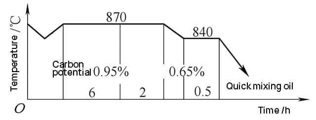
Fig. 6 gas carbonitriding process of internal gear ring
(3) Heat treatment secondary heating quenching process
After carbonitriding, the gear ring is cooled slowly and then reheated. It is then press-quenched by internal support. The process is shown in Figure 7.
The quenching temperature is 830°C for 40 minutes.
A quenching cooling medium with a mass fraction of 10% to 15% PM is used for quenching. The transfer time is 20 seconds, the cooling time is 10 seconds, and the outlet temperature is controlled at 150 to 180°C, which is approximately pressure quenching.
Special tooling is used to temper the inner hole of the internal support.
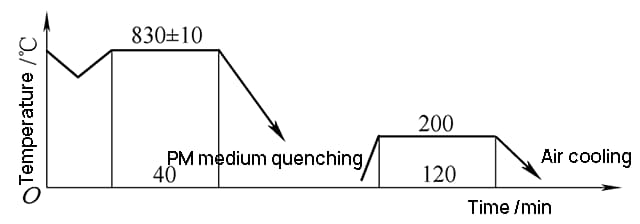
Fig. 7 secondary heating quenching and tempering process of internal gear ring
(4) Tooling and furnace charging method
The internal-to-external diameter ratio of the internal gear ring is significantly greater than 1/2, and the wall is thin.
This can result in roundness distortion during quenching.
To reduce the impact of gravity, overlapping stacking should be avoided.
A reasonable spacing between the gear rings should be maintained to ensure uniform circumferential cooling.
(5) Quenching distortion and control
A substantial amount of allowance should be reserved based on the heat treatment to ensure dimensional accuracy.
The secondary heating quenching process is chosen.
The quenching is performed using a quenching press.
Parts with roundness outside of tolerance after quenching should be reshaped and tempered using special tooling.
(6) Inspection results
The surface hardness is 60 ~ 65HRC, the core hardness is 38 ~ 40HRC, the martensite and residual austenite are grade 1, the carbon nitrogen compound is grade 1, and the outer diameter roundness is 0.13 ~ 0.30mm. All are qualified.
The size of the gear ring is 322mm (outer diameter), 281mm (inner diameter), and 77mm (width).
The material used is 50Mn2 steel. The technical requirements for medium-frequency quenching are: the surface hardness should be between 50 and 55HRC, and the hardened layer at the tooth root should be 1 to 4mm in depth and equivalent to 40HRC.
The accumulated pitch error of the gear ring should be less than 0.10mm, the tooth direction error should be less than 0.055mm, and the tooth shape error should be less than 0.035mm.
(1) Medium frequency quenching machine tool and inductor
The rated power of the medium-frequency quenching machine tool should not be less than 400KW.
The inductor is made from 14mm x 14mm copper square tubing with 5 turns. The height of the inductor is “a”, and a gap of “b” is reserved between the gear ring and the inductor.
Figure 8 is a schematic diagram of the inductor.
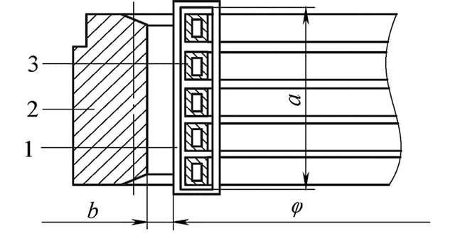
Fig. 8 schematic diagram of inductor for gear ring
1. Conductive magnet
2. Gear ring
3. Sensor
(2) Specification for medium frequency heating and quenching
A clearance of “b + 2mm” is reserved between the gear ring and the inductor to account for the influence of the magnet on the magnetic field distribution. The height of the inductor is also increased to “a + 3mm”.
The electric heating specifications are: the maximum output voltage is 540V, the maximum output current is 430A, and the frequency is 8000Hz.
After 22 seconds of heating, the heated area becomes bright red, indicating that the temperature required for quenching has been reached.
The heating mode is simultaneous heating and quenching.
The common specific power is between 0.8 and 1.5kw/cm2.
The quenching and cooling medium used is AQ251 quenching and cooling medium from Houghton company, with the concentration proportion controlled at 9% to 13% (mass fraction).
(3) Inspection results
The metallographic structure inspection and dimension inspection fully meet the technical requirements.
The depth of hardened layer of tooth root is 2.5 ~ 4.0mm.
Tooth direction runout < 0.05mm, tooth shape runout < 0.04mm, and circumferential cumulative error < 0.1mm.
(1) The latest induction heating die press quenching technology
The latest die press quenching process of German EMA combines the advantages of induction quenching and pressure quenching process.
Its main advantages are:
This technology has been successfully implemented in the automobile parts industry. It is suitable for both direct pressure quenching of medium-carbon steel gears and pressure quenching of carburized gears, including high-precision ring components such as gear rings, bevel gears, and synchronous rings.
Figure 9 illustrates the flow chart for the process of heat treatment distortion correction for gear ring mold pressing induction hardening.
Step 1: Secure the distorted gear ring to the non-magnetic centering and clamping device. The clamping device consists of a solid bottom die and an upper die.
Step 2: Heat the gear ring to approximately 900°C using electromagnetic induction. The heating temperature is determined based on the material and can be monitored and controlled using an infrared thermometer.
Step 3: After a certain holding time, the gear ring reaches a uniform temperature. The upper and lower dies are then pressurized.
Step 4: Immediately quench the gear ring by spraying it with a cooling medium.
Step 5: Move the inductor to the combined position of the ring gear and correction core mold.
Step 6: Tempering and heating the gear ring.
Step 7: As the temperature rises, the gear ring expands slightly, creating a small gap.
Step 8: Remove the gear ring from the other end of the core die.
The correction core die, made of stainless steel, effectively prevents the gear ring from contracting.
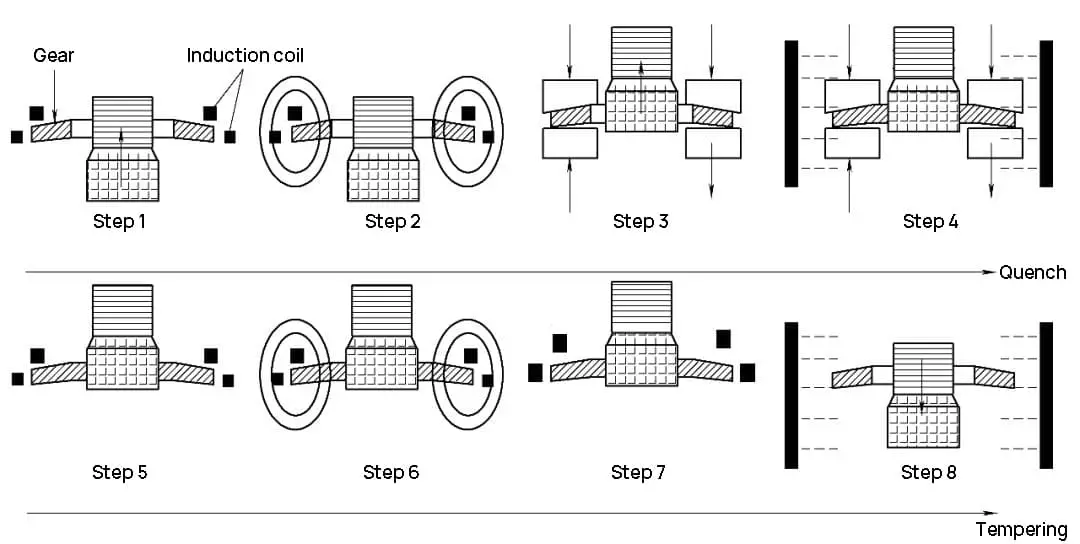
Fig. 9 flow chart of distortion gear ring die pressing induction hardening
(3) Process parameters and results
See Table 2 for process parameters and results.
It can be seen from table 2 that the gear distortion is small: concentricity < 0.03mm, roundness < 0.03mm, flatness < 0.05mm.
Table 2 pressure quenching process parameters and inspection results of 16MnCrS5 steel gear
| Process parameters | Power / kw | 250 |
| Frequency / kHz | 10 | |
| Process time / min | 4 | |
| Hardness and hardened layer | Surface hardness HV30 | 680~780 |
| Depth of hardened layer / mm | 0.8~1.2 | |
| Core hardness HV30 | 350~480 | |
| Accuracy | Concentricity / mm | <0.03 |
| Roundness (inner diameter) / mm | <0.03 | |
| Flatness (bottom surface) / mm | <0.05 |
The dimension of the thin-walled gear ring is φ162mm (outer diameter), φ111.4mm (inner diameter), and 48mm (thickness). It is made of 20CrMnTi steel.
The technical requirements for the gear ring are as follows:
(1) Distortion of original equipment, process and gear ring
The original heat treatment adopts a continuous carburizing furnace, and the carbonitriding process is: strong carburizing 880 ℃ → diffusion 860 ℃ → 840 ℃ cooling and quenching.
Because of the complex structure, thin wall, and asymmetry of the gear ring, the roundness of the inner hole after carbonitriding quenching is greater than or equal to 0.12mm, causing the distortion to fall outside of the tolerance range.
(2) Improved heat treatment equipment and process
The production line has been changed to a 2-1-1 multi-purpose furnace, which allows for uniform and accurate control of temperature and carbon potential.
By controlling the depth of the carburized layer, it was found that a shallower layer leads to a lower carbon potential and reduced distortion. Therefore, the carburized layer is precisely controlled at a depth of 0.6 to 0.7mm, and the metallographic structure is kept at level 1 to 2.
Co infiltration process: intensive infiltration 860 ℃ → diffusion 860 ℃ → 830 ℃ cooling quenching (quenching adopts Jinyu Y35 – Ⅰ isothermal graded quenching oil).
Through inspection, the roundness of the inner hole is controlled within 0.10mm, which is qualified.
The internal gear size for the combine is φ315mm (outer diameter), φ268.2mm (inner diameter), and 36mm (width). The material used is 20CrMnTi steel with a modulus of 4mm.
The technical requirements for the internal gear are as follows:
(1) Original process and distortion of gear ring
Original process: rough machining → carburizing → finish machining → secondary heating and quenching.
After heat treatment, the distortion of the inner hole is large, and the roundness of the inner hole is between 0.35 and 0.80mm, and the distortion is out of tolerance.
(2) Improved process and inspection results
An improved gear material has been selected with the approval of the main engine manufacturer. It is decided to adopt 40Cr steel.
The gear material will undergo overall quenching and tempering treatment to ensure the hardness (strength) of the gear core, followed by high-frequency quenching of the teeth to prevent distortion from falling outside of the tolerance range.
The new technical requirements for the gear material are as follows:
New technological process: rough machining of gear blank → quenching and tempering → finish machining → high frequency quenching.
Inspection results: through multiple matching tests of cold and hot machining, the parameter m value of internal gear before heat treatment was adjusted, and the technical requirements were met after high-frequency quenching.
Using 40Cr steel for high-frequency quenching instead of 20CrMnTi carburizing quenching also reduces the cost, and the effect is good after loading.
The correction method for forming ellipse after quenching of gear ring is as follows:
The Hot Spot Correction method is based on the principle of heating and immediately cooling the convex part of the outer circle of the gear ring (at the elliptical long axis point), which reduces it through the cold shrinkage effect. The hot spot can be rectified by heating it with an acetylene oxygen or propane oxygen flame.
Specifically, there are two hot spots located symmetrically on the outer diameter of the long axis of the ellipse and one hot spot at both ends of the symmetrical inner diameter of the short axis. The hot spots should be cooled immediately after heating, for example by using water cooling.
If the ovality is excessive, the heating counterattack method can be used for a preliminary correction, followed by the hot spot correction method for further correction, resulting in a satisfactory outcome.
Finally, low-temperature tempering should be performed at a temperature between 170-200 ℃ for 1 hour, followed by a recheck.

As the founder of MachineMFG, I have dedicated over a decade of my career to the metalworking industry. My extensive experience has allowed me to become an expert in the fields of sheet metal fabrication, machining, mechanical engineering, and machine tools for metals. I am constantly thinking, reading, and writing about these subjects, constantly striving to stay at the forefront of my field. Let my knowledge and expertise be an asset to your business.