8 Welding Safety Accidents You Need to Know
Have you ever wondered how a simple welding task can turn deadly in an instant? This article explores real-life welding accidents, revealing the critical safety measures often overlooked. Learn essential…
Imagine you could transform simple metal pieces into complex structures with just a few precise steps. This article dives into the essential steps of welding, from preparation to finishing touches. Learn how to ensure clean, strong welds and avoid common pitfalls. Whether you’re a novice or looking to refine your technique, discover the secrets to mastering the art of welding. Get ready to enhance your skills and achieve flawless results!
Before installation, each component should be examined for quality (including model, values, voltage resistance, and polarity). Any components that do not meet these standards must be replaced promptly.
Next, the leads of each component should be cleaned with sandpaper or a knife to expose the metallic luster, then coated with flux for thinning.
Finally, the leads of the components should be bent according to the lengths required by their placement on the circuit board.
When bending the leads, ensure the markings are facing outward. Hold the base of the component with tweezers in one hand, and bend the lead with the other, creating an arc at the bend.
Installation should be guided by the installation diagram. Normally, the diagram is oriented with the copper foil side of the printed circuit board facing up, and the component side facing down.
Start by installing large components, then insert smaller components such as resistors and capacitors into the soldering holes.
Components should be arranged neatly and aesthetically, with model numbers and values facing outward for easy visibility, which will facilitate inspection and maintenance. Finally, after testing the transistors or integrated circuits, they can be inserted into the soldering holes and soldered.
Soldering Techniques:
Once the components are installed on the printed circuit board, the next step is to solder.
You can either solder each component individually as they are installed, or install all components first and then solder them all at once.
Either way, the same general requirements apply.
The soldering iron tip must be kept clean and free of soldering slag and other oxidants.
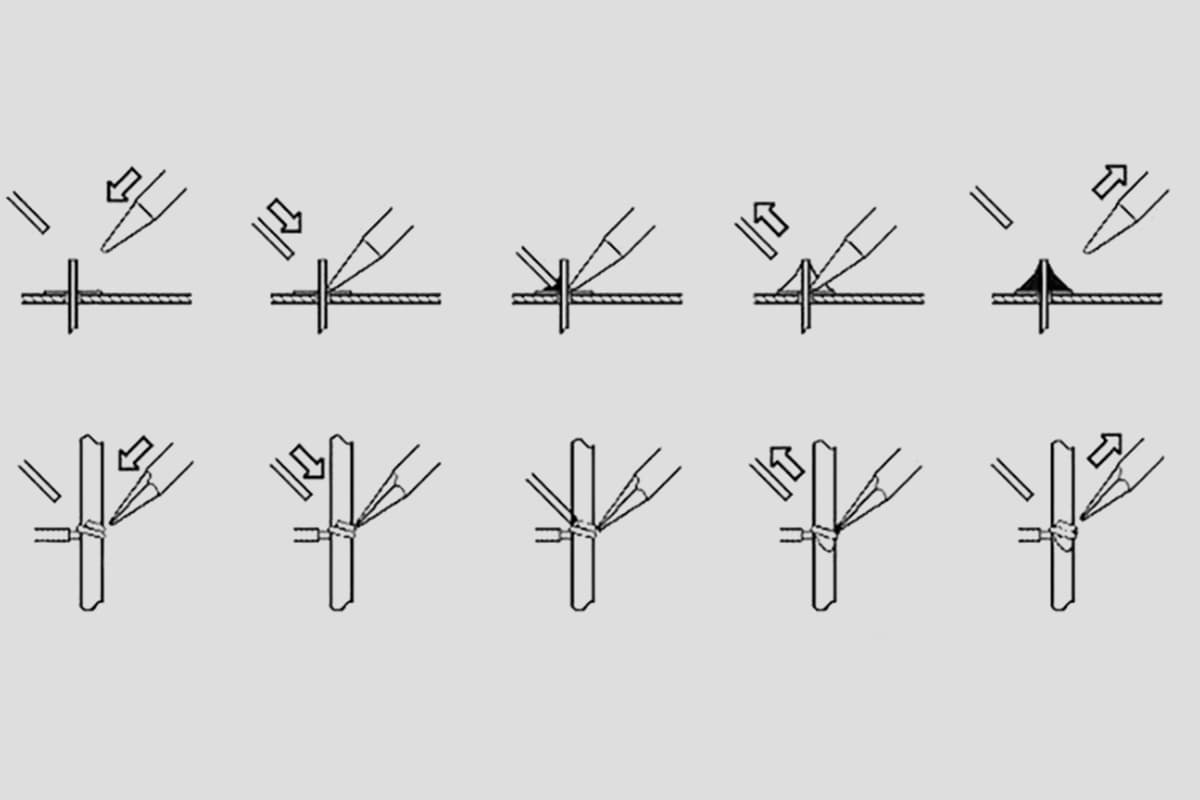
Apply appropriate pressure to the area being heated with the soldering iron. The angle between the iron and the copper foil should be around 40 to 60 degrees.
When soldering components onto a printed circuit board, ensure that the iron is in contact with both items being soldered, so that heat is evenly distributed.
For components with low heat capacity, like thin wires on a printed circuit board, this step may be skipped.
During heating, all parts of the component that require tinning should be evenly heated, not just one part. Avoid adding pressure with the iron to prevent damage or hidden hazards.
First, apply a small amount of solder to the copper foil and component supply points to improve thermal conductivity.
If there are pins, add a small amount of solder to the cut surface of the pins to prevent oxidation.
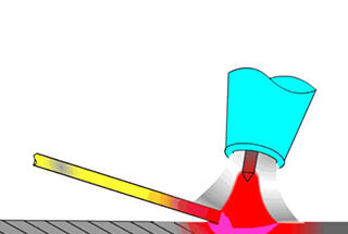
Due to the nature of solder flowing from low to high temperatures, slowly feed the solder wire from a point far away from the soldering iron, adjusting the quantity and speed of supply accordingly.
Avoid supplying solder directly to the soldering iron tip. The soldering iron tip should be placed in a position where it can simultaneously heat the copper foil and component.
Depending on the size and material of the copper foil, if the copper foil and component are large, the contact area of the soldering iron tip should be large; conversely, if they are small, the contact area should be small.
This allows the copper foil and component to reach the same temperature at the same time.
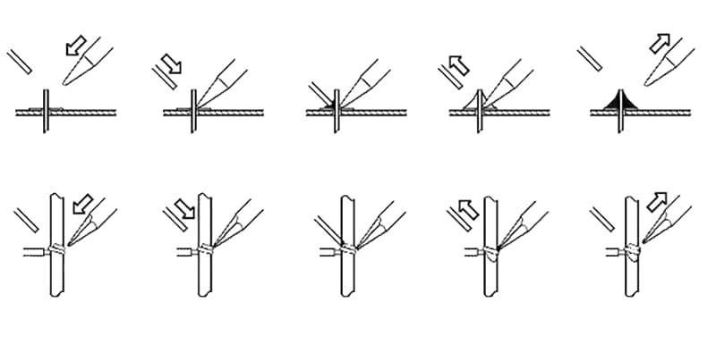
Once a certain amount of solder wire has melted, immediately move the solder wire 45° to the upper left.
The soldering iron should be withdrawn towards the upper right corner. Do not move the soldering iron until the solder has completely spread to the edge of the copper foil.
The time from step 5 to step 7 should be approximately 1 to 2 seconds. For welding quality, the contact time between the soldering iron and copper foil should not exceed 3 seconds.
The removal of the soldering iron requires precision. The timing, angle, and direction of the iron’s withdrawal are pivotal to the formation of the solder joint. The direction of the soldering iron’s removal can affect the amount of tin in the solder joint.
Place the soldering iron tip – still adhered with solder – on the soldering iron stand.
Welding Precautions:
1) When performing tin soldering, follow the sequence from left to right and top to bottom to avoid missed inspection or repair during welding.
2) Clean the soldering iron tip frequently during welding to prevent defects such as false welding, pinholes, and over-soldering caused by debris on the soldering iron tip.
3) Do not add solder to the soldering iron tip on the substrate. During the production process, do not shake, knock, or flick the solder to prevent solder slag or beads from falling onto the substrate.
4) When pressing or disassembling components, first add solder to the copper foil surface of the circuit board. Ensure uniform heating to prevent the rosin from becoming ineffective or the copper foil from curling and damaging the circuit.
5) After using the soldering iron, securely place it on the soldering iron stand. Be careful not to touch the soldering iron tip with wires or other debris to avoid burning the wires, causing electrical leaks or other accidents.
6) Keep the soldering iron tip clean: During welding, the soldering iron tip remains at a high temperature and is in contact with weakly acidic substances such as flux, making its surface prone to oxidation, corrosion, and the accumulation of black impurities.
These impurities form an insulating layer, hindering heat transfer between the soldering iron tip and the soldered components.
Therefore, always clean the soldering iron tip with a damp cloth or a wet wooden fiber sponge. For regular soldering iron tips, a file can be used to remove the surface oxidation layer when corrosion and contamination are severe. However, this method should never be used for long-life soldering iron tips.
7) Use an appropriate amount of flux: A suitable amount of flux is very beneficial for soldering. Overuse of rosin flux requires the removal of excess flux after soldering and prolongs the heating time, reducing work efficiency.
If the heating time is insufficient, it is easy to form a “slag inclusion” defect. When soldering switches and connectors, excess flux can flow onto the contact point, causing poor contact.
The appropriate amount of flux should be just enough to wet the part that will form the solder joint and should not flow through the holes in the printed circuit board. For soldering using rosin core solder wire, there is basically no need to apply additional flux.
8) To reduce the harm of chemicals volatilized during the heating of flux to humans and to reduce the inhalation of harmful gases, the distance from the soldering iron to the nose should generally not be less than 20cm, usually around 30cm is suitable.

As the founder of MachineMFG, I have dedicated over a decade of my career to the metalworking industry. My extensive experience has allowed me to become an expert in the fields of sheet metal fabrication, machining, mechanical engineering, and machine tools for metals. I am constantly thinking, reading, and writing about these subjects, constantly striving to stay at the forefront of my field. Let my knowledge and expertise be an asset to your business.