Ever wondered how welding engineers tackle the most common issues in their field? From understanding weld defects to mastering the best techniques for different materials, this article covers 80 essential FAQs that every welding professional must know. Dive into this comprehensive guide to learn practical solutions and tips that will enhance your welding skills and ensure high-quality results in your projects. Whether you’re dealing with undercuts, choosing the right welding method, or ensuring safety, this resource has got you covered.
1. What are the hazards of pores formed during welding?
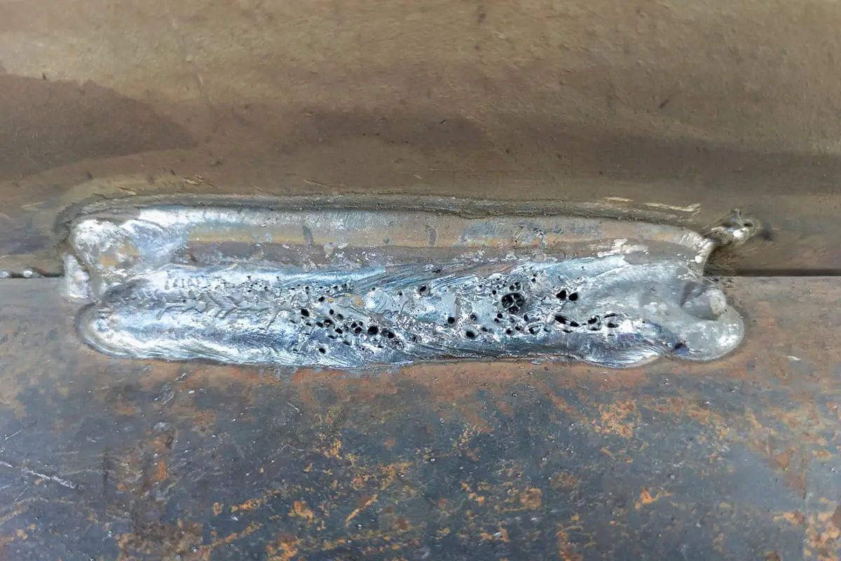
The presence of pores in a weld can weaken its effective working section, resulting in a decrease in the mechanical properties of the weld, such as its plasticity, bending, and impact toughness.
In cases where the pores are severe, the metal structure can sustain damage during operation, especially in environments with alternating stresses such as water hammer, mechanical vibration, temperature changes, etc.
2. What are the reasons and prevention methods for the non-compliance of weld surface size with the requirements?
Causes: The incorrect groove angle of the weldment, uneven assembly gaps, improper welding speed, or incorrect electrode transportation methods, and the improper selection or change of electrode and angle can all lead to welding issues.
Prevention method: To prevent these issues, it’s essential to select the appropriate groove angle and assembly clearance.
Additionally, correctly selecting the welding process parameters, especially the welding current value, and adopting appropriate strip transportation methods and angles will ensure a uniform weld formation.
3. What are the causes and prevention methods of undercut?
Causes: Improper selection of welding process parameters, excessive welding current, prolonged arc, incorrect strip transportation speed, and electrode speed are the main causes.
Prevention method: To prevent this, it is important to choose the appropriate welding current and speed, avoid excessively long arcs, and master the correct strip transportation method and angle.
4. What are the functions of drug skin?
The coating layer pressed on the surface of the welding core is called coating.
Its function is:
(1) Improve the stability of the welding arc.
(2) Protect the molten metal from external air.
(3) Transition alloy elements are added to achieve the required weld properties.
(4) Enhance the welding process performance and productivity.
5. What is the purpose of quenching?
The process of heat treatment involves heating steel parts to a temperature above Ac3 or Ac1, maintaining it for a certain period of time, and then cooling it at an appropriate speed to obtain either martensite or bainite. This process is commonly referred to as quenching, and it is utilized to improve the steel’s hardness, strength, and wear resistance.
6. What is the purpose of steel annealing?
To facilitate cutting and cold deformation processing, the hardness of steel needs to be reduced while improving its plasticity.
The grain size of steel needs to be refined, and its structural composition needs to be homogenized to improve its properties or prepare it for future heat treatment.
Residual internal stress in steel needs to be eliminated to prevent deformation and cracking.
7. What are the general principles for groove selection?
It can ensure proper workpiece penetration (generally between 2mm-4mm in manual arc welding) and make welding operations more convenient.
The groove shape should be easy to process.
It can improve welding productivity and minimize the usage of welding rods.
It aims to minimize workpiece deformation after welding.
8. What are the characteristics of CO2 gas shielded welding? What is the cause of splash?
It is characterized by:
(1) CO2 gas oxidation;
(2) The cooling effect of air flow creates pores in the weld as the molten pool solidifies rapidly. However, this process is beneficial for thin plate welding and results in less deformation after welding.
(3) Welded joints with low hydrogen content exhibit high cold crack resistance in CO2 gas shielded welding.
(4) Carbon dioxide gas shielded welding is often associated with spatter, which is its main disadvantage.
The causes of splash are as follows:
Splash caused by carbon monoxide gas;
Splash caused by pressure fluctuations in the spray nozzle;
Splash caused by a short circuit.
9. How to check the air tightness of welded containers with ammonia inspection method?
Fill the pressure element with compressed air mixed with 1% ammonia, and affix a paper or bandage that has been soaked in a 5% mercuric nitrate aqueous solution on the outside of the weld. Alternatively, white paper that has been soaked in phenolphthalein reagent can also be used.
If there is a leak, black spots (or red spots when using phenolphthalein paper) will appear at the corresponding position of the paper strip or bandage.
This method is highly accurate and efficient, especially for verifying the tightness of the weld in low ambient temperatures.
10. What are the types of welding methods?
Welding is categorized into three groups, based on the adopted energy and process characteristics: fusion welding, pressure welding, and brazing. Each of these categories is further divided into various welding methods.
Fusion welding is divided into six types: arc welding, gas welding, thermit welding, electroslag welding, electron beam welding, and laser welding.
Pressure welding is divided into seven types: resistance spot welding, seam welding, resistance butt welding, ultrasonic welding, explosive welding, diffusion welding, friction welding, and high-frequency welding.
Brazing, on the other hand, comprises flame brazing, induction brazing, furnace brazing, salt solution brazing, and electron beam brazing.
Arc welding has four subcategories: electrode arc welding, stud welding, gas shielded welding, submerged arc welding, and plasma arc welding. Gas shielded welding is further divided into argon arc welding, titanium dioxide arc welding, and atomic hydrogen welding.
Metal thermal cutting, spraying, and carbon arc gouging are metal processing methods that are similar to welding techniques. They usually fall within the technical scope of welding specialties.
11. What are the effects of groove angle, root clearance and blunt edge?
The groove angle is the angle included between two surfaces of a groove.
The root gap is the gap left between the root of a joint before welding. Its function is to ensure root penetration during backing welding.
A blunt edge refers to the straight edge of the end face along the root of the joint groove of the weldment when the weldment is beveled. It is used to prevent the root from burning through.
12. What should be paid attention to in the use and maintenance of AC arc welding machine?
The welding machine shall be used according to its rated welding current and load duration, and shall not be overloaded.
The welder should not be subjected to a long-term short circuit.
The current regulator should operate under no load.
It is important to frequently check the wire contacts, fuses, grounding, and regulating mechanism to ensure they are intact.
To prevent the invasion of dust and rain, it is important to keep the welding machine clean, dry, and well-ventilated.
After work, the welding machine should be placed stably and the power should be cut off.
The welding machine should be regularly overhauled.
13. Safe operation technology of manual arc welding?
(1) Please note that the no-load voltage should not exceed the rated value, which is AC 60V or DC 90V.
(2) Protective glasses must be provided for removing welding slag.
(3) Construction areas with a large number of people should have shutters to prevent household arc radiation.
(4) Welding tongs with welding rods should not be placed randomly.
(5) Welding rod heads must not be thrown carelessly; instead, they should be stacked centrally. Special attention must be paid to fire prevention.
(6) When welding non-ferrous metals, galvanized pipes, or alloys, masks should be worn to prevent the inhalation of zinc oxide.
(7) The site, tools, and equipment should be cleaned, and the power supply should be disconnected at the end of the work.
(8) The welding machine’s shell should be grounded.
(9) When vegetation ash is needed for thermal insulation and slow cooling, be careful of surrounding objects to prevent fire.
(10) Disconnect the power supply before moving the welding machine or changing the wiring.
(11) Welding should be conducted inside the vessel while being supervised outside.
(12) When welding and repairing containers or pipes that contain flammable and explosive media, they should be replaced and qualified, and all covers should be opened.
14. What are the functions of flux in the welding process?
In welding, flux is the main factor to ensure welding quality.
It has the following functions:
(1) Upon melting, the flux rises to the surface of the molten metal to safeguard the molten pool and prevent the erosion caused by harmful gases present in the atmosphere.
(2) The flux aids in deoxidization and alloying, and in conjunction with the welding wire, attains the necessary chemical composition and mechanical properties of the weld metal.
(3) It assists in achieving a well-formed weld.
(4) It reduces the cooling rate of the molten metal, thereby minimizing defects like pores and slag inclusions.
(5) Furthermore, it prevents splashing, reduces loss, and enhances the bonding coefficient.
15. What are the advantages and disadvantages of manual arc welding?
Advantage:
(1) The process is flexible and highly adaptable;
(2) High-quality output is ensured;
(3) The deformation can be easily controlled and stress can be improved through process adjustments;
(4) The equipment is simple and easy to operate.
Disadvantages:
(1) The requirements for welders are stringent, and the welding operation technology and experience directly impact the product’s quality. (2) Working conditions may be subpar, and (3) productivity may be low.
16. What is the meaning and influencing factors of welding thermal cycle?
During the welding process, the heat source moves along the weldment, causing changes in temperature at different points over time. This phenomenon is known as the welding thermal cycle of the point.
Influencing factors:
(1) Welding process parameters and linear energy;
(2) Preheating and interpass temperature; plate thickness, joint form, and thermal conductivity of materials.
17. What are the causes and prevention methods of hot cracks?
Causes:
It is the result of the tensile stress when the molten pool cools and crystallizes, and the liquid thin layer formed by low melting point eutectic during solidification.
Prevention methods:
Control the content of harmful impurities, such as carbon, sulfur, and phosphorus, in the weld to reduce the formation of eutectic at the bottom melting point in the molten pool.
Preheat the material to reduce the cooling rate and improve the stress condition.
Use alkaline electrodes because they have strong desulfurization and dephosphorization abilities in their slag.
Control the weld shape and try to avoid creating deep and narrow welds.
Use hand arc plates to guide the arc pit to the outside of the weldment. This helps prevent arc pit cracks from affecting the weldment.
18. What is the relationship between weld forming factor and weld quality?
During fusion welding, the ratio between the weld width (b) and the calculated weld thickness (H) on the cross section of a single weld, denoted as ф= B / h, is known as the weld forming factor.
A smaller weld forming factor indicates a narrower and deeper weld, which may increase the likelihood of pores, slag inclusions, and cracks in the weld. Thus, it is important to maintain the weld forming factor at an appropriate level.
19. What are the causes and prevention methods of pores during welding?
(1) For manual arc welding, a 10mm space on both sides of the weld should be left buried. For automatic arc welding, rust and other surface dirt within 20mm on both sides of the weldment should be carefully removed.
(2) Before welding, the welding rod and flux must be strictly dried according to regulations and stored in an insulation barrel for easy use and access.
(3) Ensure appropriate welding process parameters are adopted. When using an alkaline electrode for welding, short arc welding must be carried out.
20. What are the alloying methods of weld metal?
The alloying of weld metal is to transfer the required alloy elements to the weld metal (surfacing metal) through the welding material to make the weld metal composition meet the required requirements.
The causes of cold cracks mainly include the following three aspects:
(1) The higher the hardening tendency of hardened steel, the more susceptible materials with carbon content exceeding that of 16MnR steel are to cold cracking.
(2) The role of hydrogen: During welding, the weld metal absorbs more hydrogen, and due to the rapid cooling rate of the weld, some hydrogen may remain in the weld metal.
(3) Welding stress: Hydrogen, hardened structure, and stress are the main causes of cold cracking.
Cold cracking is more likely to occur when welding low-alloy high-strength steel, medium carbon steel, alloy steel, and other types of steel, but it is less common in welding low-carbon steel and austenitic stainless steel.
22. What are the advantages of using pulsed arc in mixed gas shielded welding?
Pulse arc has been adopted in mixed gas shielded arc welding, marking a significant development in gas shielded arc technology. This innovation expands the scope of application for gas electric welding and offers the following advantages:
(1) The technique offers the benefits of both short-circuit transition and jet transition, making it suitable for welding thin and thick plates, and it is applicable to all position welding.
(2) It enables effective control of heat input to the base metal, thereby enhancing the performance of welded joints.
(3) It boasts a wide current regulation range and strong adaptability.
23. What is the difference between acid electrode and alkaline electrode?
The Acid electrode offers excellent process performance, an attractive appearance, and is insensitive to rust, grease, moisture, etc. Additionally, it has low moisture absorption, and it can be used with both AC and DC power supplies.
However, the Acid electrode has several drawbacks, including incomplete desulfurization and deaeration, no dephosphorization, poor crack resistance, and low mechanical properties.
On the other hand, the Alkaline electrode has good crack resistance, thorough deaeration, easy slag removal, beautiful weld formation, and high mechanical properties. Its main disadvantages are strong moisture absorption and poor pore resistance.
Generally, the Alkaline electrode can only use DC power supply. However, if an appropriate amount of arc stabilizer is added to the coating, it can use both AC and DC.
24. How to improve the connection strength of lap joints?
The measures to improve the connection strength of lap joints are:
(1) When the structure permits, lap joints with both side fillet welds and front fillet welds should be utilized as much as possible to reduce stress concentration and improve stress distribution.
(2) Plug welds and slotted welds should be added to the lap weld.
(3) A straight seam single-sided lap joint can utilize a sawtooth seam lap shape.
25. What is magnetic bias blowing? How to overcome?
During DC arc welding, the arc partial blow caused by the action of electromagnetic force in the welding circuit is called magnetic partial blow.
Measures to prevent magnetic bias blowing generally include:
Use short arc welding with a small current.
Properly reposition the grounding wire on the weldment and use double grounding wire.
Adjust the electrode angle to tilt towards the side where partial blowing is needed.
When welding small workpieces, wind the welding cable around the weldment for two or three turns to generate a magnetic field in the opposite direction of the magnetic bias blowing magnetic field.
26. What is the main function of preheating?
Preheating is an effective measure to reduce the cooling rate after welding. It not only prolongs the cooling time within the range of austenite transformation temperature and reduces the hardening tendency but also extends the cooling time when the maximum welding heating temperature reaches 100℃, which aids in the escape of hydrogen.
Moreover, preheating can reduce welding stress and prevent cold cracks.
27. What are the causes of slag inclusion? How to prevent?
The causes of slag inclusion are:
There is dirt present at the edge of the joint.
The groove is too small, the electrode diameter is too thick, and the welding current is too low.
During welding, the welding angle and strip transportation method are inappropriate, making it difficult to distinguish between slag and molten iron. This can lead to the mixing of molten metal and slag.
The cooling speed of the weld is too fast, and the slag does not have enough time to float to the surface.
Improper chemical composition of the base metal and welding materials can also contribute to the formation of inclusions. For example, when the molten pool contains high levels of oxygen, nitrogen, and other components, the chance of forming inclusions increases.
Measures to prevent slag inclusion include:
Remove the oxide scale from the bottom of the slag shell and groove edge.
Carry the bar correctly, swing the welding rod regularly, and stir the molten pool to separate the molten slag from the molten iron.
Improve the condition of slag floating by slowing down the welding speed and increasing the welding current to prevent the weld metal from cooling too quickly.
28. How to reduce the stress concentration of welded joints?
The measures to reduce the stress concentration of welded joints are:
Butt joints should be used whenever possible, and the reinforcement value of such joints should not be excessively large. Moreover, the weld toe should transition smoothly wherever feasible.
For T-joints (cross joints), a groove should be made or deep penetration welding should be adopted to ensure full penetration.
Welding defects, such as cracks, incomplete penetration, undercut, etc., should be minimized or eliminated.
When butt jointing steel plates of different thicknesses, the thicker plates should be thinned.
Welds should not be too dense to ensure a minimum distance.
Welds at the turning points of a structure should be avoided whenever possible.
29. What are the factors affecting the mechanical properties of welded joints?
The mechanical properties of the weld metal depend on several factors, including its chemical composition, fusion ratio, welding layer, and welding line energy.
Meanwhile, the mechanical properties of the heat-affected zone are primarily influenced by the welding line energy.
Furthermore, the overall mechanical properties of the welded joint can be affected by whether heat treatment is conducted after welding.
30. What process measures should be taken when welding 15CrMo pearlite heat resistant steel to prevent cold cracks?
To prevent cold cracks during the welding of 15CrMo steel, the following process measures should be taken:
(1) Preheat the weldment to 150 ~ 300 ℃ before welding. However, for argon arc welding backing and CO2 gas shielded welding, preheating can be reduced or omitted.
(2) Immediately cover the weld and heat-affected zone with asbestos cloth after welding to allow slow cooling.
(3) Perform high-temperature tempering at 680 ~ 700 ℃ immediately after welding.
31. Why is the welding process of surfacing transition layer often used in the welding of dissimilar steel (metal)?
The process of surfacing a transition layer is used to obtain high-quality joint performance when dissimilar metals are welded, such as steel.
For instance, when welding austenitic stainless steel and pearlite steel stabilized with boron, surfacing a transition layer on one side of the pearlite heat-resistant steel helps to reduce the size of the diffusion layer and minimize the likelihood of cracks.
Similarly, when welding steel with copper or its alloys, surfacing a transition layer on the steel or copper and its alloys helps to prevent penetration cracks and enhance the joint’s overall performance.
32. How to improve the quality of weld metal through the metallurgical reaction between slag and molten pool metal?
A series of metallurgical reactions occur during the regulation of temperature in the slag and molten pool metal. These reactions include deoxidation, dephosphorization, desulfurization, and alloying.
Proper control of these reactions can significantly improve the quality of the weld. For example, adding a sufficient amount of deoxidizer to the electrode coating can effectively deoxidize the molten pool.
Similarly, adding an adequate amount of alkaline oxide to the electrode coating or flux can partially remove sulfur and phosphorus from the molten pool. Additionally, the use of alloy elements in the flux or directly in the welding core or wire can transfer the added alloy components to the weld.
Therefore, these metallurgical reactions find extensive use in the fusion welding process.
33. When welding stainless steel, which shielding gas is more suitable?
Pure argon can be used as a protective gas when TIG welding stainless steel. However, when MIG welding stainless steel, using pure argon can result in an imperfect weld appearance due to cathode drift.
To prevent this, an argon-rich mixed gas can be used for protection. For instance, adding 1-2% oxygen or 1-2% oxygen and 5% carbon dioxide to argon can improve the weld appearance.
34. What kind of groove can be selected when full penetration welding is required for butt joint of small-diameter pipeline?
When joining small-diameter pipes using butt welding, it is not possible to carry out internal welding. Therefore, the choice of a single-sided groove is limited to the welding process of single-sided welding and double-sided forming.
For wall thicknesses that are not too thick, a V-groove can be selected. However, if the wall thickness is thick and processing conditions permit, a U-groove may be more appropriate.
If necessary, it is also possible to select a bottom locking joint or a joint with a lining ring at the bottom.
35. What is the basis for selecting the welding current during welding?
Generally, the selection of welding current is based on:
36. Why should welding electrodes be dried before use?
The performance of electrodes can often be negatively affected by various factors such as electrode coating composition, air humidity, storage mode, and storage time, leading to moisture absorption and resulting in an unstable arc, increased spatter, and a greater likelihood of defects such as pores and cracks.
To mitigate these issues, it is important to dry the electrode prior to use.
37. What are the advantages of argon arc welding of aluminum and aluminum alloys?
The main advantages of argon arc welding for aluminum and its alloys are due to the use of argon as an inert gas. It provides good protection, a stable arc, and produces beautiful weld formations.
When an AC power supply is used, the cathode crushing effect can effectively remove the alumina film from the surface of the molten pool.
During welding, there is no slag produced and therefore, there is no residue to cause corrosion of the joint.
Argon flow also has a scouring effect on the welding area, which accelerates the cooling rate of the welded joint. This improves the microstructure and properties of the joint while reducing the residual deformation of the weldment after welding.
38. Which welding method can be selected for horizontal butt welding of pipes?
In general, due to the thinness of the pipe wall, the weld formation may deteriorate when welding is performed at all positions, caused by the flowing of molten iron.
Therefore, the ideal welding method in such situations is pulsed argon arc welding. This can be done using tungsten pulsed argon arc welding or melting electrode pulsed argon arc welding, with the former being more mature at present.
The main advantage of this method is that it is easy to automate the welding process, which reduces labor intensity and the requirements for welders’ operation skills. Additionally, it is beneficial for achieving single-sided welding and double-sided forming, with good weld quality and a beautiful appearance.
39. What problems should be paid attention to when using rigid fixation method to reduce welding residual deformation?
When using the rigid fixation method to reduce welding residual deformation, it is important to note the following:
(1) The rigid fixation method can only reduce a portion of the welding residual deformation, and cannot completely eliminate it. This is because residual deformation may still occur on the weldment even after external restraints are removed.
(2) The rigid fixation method can create significant welding stress in welded joints, which can be problematic for materials prone to cracking. Therefore, caution should be exercised when using this method on such materials.
40. What is a weld “joint”? What are the key points of joint operation?
During electrode arc welding, a weld is often created using multiple electrodes due to the limited length of the electrode. Additionally, due to the welding process requirements, a weld may be formed by several short welds that are connected together.
The connection between electrodes or short welds is called the “joint” of the weld.
The following operation essentials shall be mastered when connecting:
During electrode arc welding, a weld is often created using multiple electrodes due to the limited length of the electrode. Additionally, due to the welding process requirements, a weld may be formed by several short welds that are connected together.
The connection between electrodes or short welds is called the “joint” of the weld.
41. What is the effect of welding current on welding quality?
Welding quality is directly affected by the welding current. Increasing the welding current can enhance weld penetration and ensure its quality. However, excessive current can result in weld undercut, burn-through, splashing, overheat of the weld metal structure, and increased grain size.
Moreover, the welding rod can turn red, the coating can fall off, and the protection performance can be reduced. On the other hand, if the current is too low, it can cause defects such as slag inclusion and incomplete welding.
42. How to distinguish between welding and brazing? What are the characteristics of each?
Welding involves the combination of atoms between the materials being joined, while brazing connects materials with a lower-melting-point filler metal, called solder.
Welding is known for its high mechanical strength and productivity when joining thick or large parts, but it can also lead to significant stress and deformation, and can cause changes in the microstructure of the heat-affected zone.
Brazing, on the other hand, requires lower temperatures and can result in a flat, smooth joint with an attractive appearance, as well as lower levels of stress and deformation. However, it also has lower joint strength and requires tight tolerances in the assembly process.
43. What should be paid attention to at the beginning of electrode arc welding?
At the beginning of the welding process, the temperature of the weldment is low, and it cannot rise rapidly after the arc is struck. This results in a shallow penetration depth, which can reduce the strength of the weld.
To overcome this issue, when using an acid electrode, the arc should be slightly lengthened after striking, the end of the weld should be preheated, and then the arc length should be shortened for normal welding.
On the other hand, when using an alkaline electrode, after striking the arc in front of the starting point, the electrode should be returned to the starting point for normal welding. This technique helps to improve the insufficient penetration at the starting point and results in a stronger joint.
44. What is the effect of oxygen in the welding area on the weld?
The presence of oxygen has a significant impact on the properties of the weld. As the oxygen content increases, the strength, hardness, and plasticity of the weld decrease significantly. However, it also leads to hot embrittlement, cold embrittlement, and age hardening of the weld metal.
Furthermore, oxygen affects the physical and chemical properties of the weld metal by reducing its conductivity, magnetic conductivity, and corrosion resistance. The dissolved oxygen in the molten pool can form carbon monoxide pores, burn beneficial alloy elements in the welding material, and deteriorate the weld’s overall performance.
In addition, excessive amounts of oxygen and carbon in the droplet can cause spatter and destabilize the welding process. Therefore, it is crucial to control the oxygen levels during welding to ensure high-quality welds.
45. What are the main difficulties in sheet welding? How to overcome these difficulties?
Thin plate welding poses several challenges such as burn-through, post-weld deformation, poor weld formation, and porosity.
To prevent porosity, it is essential to clean the joint area thoroughly, removing any dirt and water stains before welding. The plate edges must also be processed accurately to avoid misalignment, which can result in burn-through. The misalignment should not exceed 0.5mm. Additionally, welding process parameters should be accurately controlled to prevent defects such as burn-through, poor forming, or incomplete penetration. Any large fluctuations in welding parameters must be avoided.
For rigid fixation and to reduce welding deformation, press horses, iron or fixed welding around can be used in thin plate welding. For long welds, segmented welding methods such as the skip welding method should be adopted. Tack welding spacing should be small, and dense spot tack welding should be used, with each section being approximately 10~15mm long.
DC reverse connection method is recommended, with short arc fast linear weld bead. When production conditions permit, the weldment can be inclined 15°~20° for downhill welding to improve welding speed, prevent burn-through, and reduce deformation. Intermittent arc quenching or vertical downward vertical welding can also be used.
Finally, it is crucial to follow a reasonable welding sequence strictly to achieve the best results.
46. What are the measures to prevent welding residual deformation? What are the welding process parameters?
(1) Recommended revised version:
Choose a reasonable assembly and welding sequence.
Select an appropriate welding method and sequence.
Use the inverse deformation method when necessary.
47. What are the requirements for groove cleaning before welding?
(1) The groove must be processed according to the specified shape and size.
(2) Before welding, all rust, oil stains, water, paint, and other debris on and around the groove surface must be carefully removed. Any residues left by carbon arc gouging must also be removed.
(3) Welding should be carried out promptly after cleaning.
If the groove becomes damp or rusted for reasons other than welding, it must be cleaned again before welding.
When welding is conducted in a highly humid climate, or if dew and frost are present on or around the groove surface, it must be dried before welding.
48. Why do stresses and deformations occur during welding?
During the welding process, the weldment is subjected to localized and uneven heating and cooling, resulting in varying degrees of metal thermal expansion and contraction in different parts of the welded joint.
Since the weldment is a cohesive unit, all its parts are interconnected and mutually restrictive, making it impossible to extend or shorten them freely. This restriction leads to stress and deformation during the welding process.
49. Why is alkaline electrode beneficial to prevent welding cold crack and hot crack?
The alkaline electrode possesses good de-sulfurization (De-S) and phosphorus (P) properties, which makes it advantageous in resisting hot cracks.
The coating is composed of a significant quantity of alkaline slag-forming materials, along with a specific amount of deoxidizer and alloying agent.
At high temperatures, it reacts with hydrogen to produce hydrogen cyanide (HF), thereby reducing the hydrogen content in the weld. This reaction is beneficial in resisting cold cracks.
50. What are the characteristics of ultrasonic flaw detection compared with radiographic flaw detection?
(1) It is insensitive to thin parts and near-surface defects and is more applicable to thick parts.
(2) The flaw detection cycle is short, and the equipment is simple, low-cost, and non-harmful to the human body.
(3) However, the nature of welding defects cannot be directly judged through ultrasonic inspection.
51. What are the causes of incomplete penetration?
There are several factors that can cause issues during welding. These include a weld groove with a blunt edge that is too large, a groove angle that is too small, an uncleared weld root, a gap that is too small, incorrect electrode or welding wire angle, low current, fast speed, excessively long arc length, and magnetic bias blowing during welding.
Additionally, using too much current can cause the welding rod to melt too quickly, before the metal of the weldment has been fully heated.
Other factors that can contribute to welding issues include rust, oxide scale, and oil stains that are not removed between layers or at the edge of the base metal. Poor welding position and accessibility can also lead to issues.
52. Why is electrode forward welding suitable for sheet welding?
When tilting forward, the weld formation coefficient increases, resulting in a shallow penetration depth and wider weld. This method is ideal for welding thin plates.
However, tilting forward weakens the effect of the arc force on the molten pool’s back row metal, leading to thicker liquid metal at the bottom of the molten pool. This hinders the heating effect of the arc on the base metal and reduces the weld thickness.
Simultaneously, the preheating effect of the arc on the unmelted base metal in front of the molten pool strengthens, causing an increase in weld width and a decrease in reinforcement. This method is also suitable for welding thin plates.
53. What are the measures to prevent air holes?
Preventive measures include:
(1) Carefully remove rust and other dirt on the surface of the weldment within 10mm on both sides of manual arc welding weld and 20mm on both sides of automatic submerged arc welding.
(2) Strictly dry the welding rod and flux according to regulations before welding and store them in an insulation barrel for easy access.
(3) Use appropriate welding process parameters. When using an alkaline electrode for grounding, short arc welding must be used.
54. What are the advantages and disadvantages of argon arc welding and carbon dioxide gas shielded welding?
Argon arc welding is characterized by small weld penetration and minimal working deformation. This method produces high weld density, making it less prone to defects such as slag inclusion, air holes, undercut, and others. The resulting weld meets stringent non-destructive testing requirements and exhibits excellent strength, toughness, and plasticity.
Additionally, its mechanical properties in terms of tensile, bending, and impact indexes surpass those of other welding techniques. Argon arc welding is particularly suited for single-sided welding, double-sided forming, and thin-wall welding.
However, its drawbacks include low work efficiency and high processing costs, which can vary significantly with market conditions.
Alternatively, CO2 gas shielded welders are highly efficient and relatively low-cost, and can be used for many on-site operations that meet general inspection requirements. They are especially suitable for keeping up with the pace of work using manual labor. Nevertheless, the disadvantages of CO2 gas shielded welding are also apparent. It is generally limited to use in scenarios where strict welding quality control is mandated by the state.
55. What welding wires and electrodes are used for welding 55.12cr1mov and 20 steel?
Firstly, let us consider the type of dissimilar steel that needs to be welded. If it is carbon structural steel, low strength welding rods should be selected. This means that welding rods with low welding strength should be used.
If one of the two dissimilar steels is an alloy steel, it is essential to compensate for the loss of alloy elements during the welding process. In such a scenario, the welding electrode for alloy steel must be chosen.
56. What is weldability? What is the weldability of carbon steel?
Weldability refers to the capacity of materials to be welded into components as per the specified design requirements under limited construction conditions and meet the predetermined service requirements.
Weldability is influenced by four factors: material, welding method, component type, and service requirements. Carbon steel is an iron-carbon alloy based on iron.
Carbon is an alloy element, and its mass fraction is no more than 1%. Furthermore, the mass fraction of manganese is no more than 1.2%, and the mass fraction of silicon is no more than 0.5%. These latter two elements are not used as alloy elements.
Other elements, such as Ni, Cr, and Cu, are controlled within the limit of residual amounts and are not used as alloy elements.
Impurity elements, such as S, P, O, and N, are strictly limited according to various steel varieties and grades.
Therefore, the weldability of carbon steel mainly depends on the carbon content. The weldability gradually deteriorates with the increase of carbon content, and the weldability of low-carbon steel is the best, as shown in Table 1.
Table 1 shows the relationship between weldability and carbon content of carbon steel.
name
Mass fraction of carbon (%)
Typical hardness
Typical use
Weldability
mild steel
≤0.15
60HRB
Plates,, and
excellent
0.15~0.25
90HRB
Structural profiles, plates and bars
good
Medium carbon steel
0.25~0.60
25HRC
Machine parts and tools
Medium (heat required, post heat, low hydrogen welding method)
Inferior (preheating and post heating are required, and hydrogen welding method is required for the core)
57. Welding process of pearlite heat resistant steel?
Steel that possesses sufficient strength and oxidation resistance at high temperatures is known as heat-resistant steel.
Low-alloy heat-resistant steel is primarily composed of Cr and Mo as the primary alloying elements. The matrix structure consists of pearlite (or pearlite + ferrite), which is referred to as Pearlite Heat-resistant steel. Commonly used steel grades include 15CrMo, 12CrMoV, 12Cr2MoWVTiB, 14mnmov, 18mnmonb, and 13mnnimonb.
Because Pearlite Heat-resistant steel contains a certain amount of Cr, Mo, and other alloying elements, a hard and brittle martensite structure can be generated in the heat-affected zone.
During welding at low temperatures or for welding rigid structures, cold cracks are prone to form. Therefore, the following process measures should be taken during welding:
(1) Preheating
Preheating is a crucial process in welding heat-resistant steel with a pearlite structure.
To guarantee welding quality, the workpiece must be preheated and kept at a temperature of 80 to 150 ℃ during tack and formal welding.
When using argon arc welding or CO2 gas shielded welding for backing, the preheating temperature can be reduced or skipped altogether.
(2) Slow cooling after welding
Immediately after welding, cover the weld and heat affected zone with asbestos cloth to cool it slowly.
(3) Post weld heat treatment
Immediate high-temperature tempering should be performed after welding to prevent delayed cracking, alleviate stress, and improve the microstructure.
It is important to avoid the temperature range of 350 ~ 500 ℃ during the post-weld heat treatment, as this range can cause strong fire brittleness in Pearlite Heat-resistant steel.
Table 2 illustrates the recommended post-weld heat treatment temperature for several commonly used pearlitic heat-resistant steels.
High temperature tempering temperature after welding (℃)
15CxMo12Cx1MoV20CxMo12Cx212Cx3MoVSiTiB
>10> 6 Any Thickness any thickness
680 ~ 700720 ~ 760720 ~ 760760 ~ welding and cutting union 780740 ~ 780
58. How to weld low carbon steel at low temperature?
When welding low-carbon steel structures in severe winter, the fast cooling speed of the welded joint increases the tendency for cracks to form. This is particularly true for the first weld of a thick and large structure, which is more susceptible to cracking.
Therefore, the following process measures should be taken:
Preheat the metal before welding, and maintain a consistent interpass temperature during welding that is not lower than the preheating temperature.
Use low hydrogen or ultra-low hydrogen welding materials.
During tack welding, increase the welding current, slow down the welding speed, increase the cross-sectional area and length of tack welds, and preheat if necessary.
The entire weld should be completed without interruption if possible.
Do not carry out arc striking on the base metal outside the groove surface, and fill the arc pit during arc extinguishing.
Avoid bending, straightening, and assembling weldments at low temperatures as much as possible.
Please refer to Table 3 for the preheating temperature required during low-temperature welding of various metal structures, and Table 4 for the preheating temperature required during low-temperature welding of pipes and pressure vessels.
Table 3 preheating temperature of low temperature welding of low carbon steel metal structure
Thickness of weldment (mm)
Preheating temperature at various temperatures
<3031~5051~70
Do not preheat when it is not lower than – 30 ℃; Preheating below – 30 ℃; Do not preheat when 100 ~ 150 ℃ is not lower than 10 ℃; Preheating when the temperature is lower than 10 ℃; Do not preheat when 100 ~ 150 ℃ is not lower than 0 ℃; Preheat 100 ~ 150 ℃ when it is lower than 0 ℃
Table 4 preheating temperature of low temperature welding of low carbon steel pipeline and pressure vessel
Thickness of weldment (mm)
Preheating temperature at various temperatures
<16173031^4041~50
Do not preheat when it is not lower than – 30 ℃; Preheat at 100 ~ 150 ℃ below – 30 ℃ and not below – 20 ℃; Preheating below – 20 ℃; Do not preheat when 100 ~ 150 ℃ is not lower than 10 ℃; When the temperature is lower than – 10 ℃, the pre heating temperature is not lower than 100c150 ℃, and when there is no – 0 ℃, the pre heating is not required; Preheat 100 ~ 150 ℃ when it is lower than 0 ℃
(1) When it comes to manual arc welding, selecting the right welding rod is crucial. For common low carbon steel Q235, the average tensile strength is 417.5 MPa. As per the principle of equal strength, the recommended welding rod for this steel grade would be the E43 series.
For more information on electrode selection for manual arc welding of low carbon steel with different grades, please refer to Table 5.
Table 5 selection of electrodes for low carbon steel manual arc welding
Steel grade
Model of welding rod selected for general structure
Model of welding rod for pressure vessel and low temperature welding
Q235
E4313,E4303,E4301,E4320,E4311
E4316,E4315(E5016,E5015)
Generally not preheated
Q255
Generally not preheated
Q275
E4316,E4315
E5016,E5015
Preheating of thick plate structure above 150 ℃
08、10、15、20
E4303,E4301,E4320,E4311
E4316,E4315(E5016,E5015)
Generally not preheated
25
E4316,E4315
E5016,E5015
Preheating of thick plate structure above 150 ℃
20g22g
E4303,E4301
E4316,E4315(E5016,E5015)
The preheating of thick plate structure is 100 ~ 150 ℃, and the welding and cutting alliance is generally not pre executed
20R
E4303,E4301
E4316,E4315(E5016,E5015)
Note: the model of welding rod in brackets in the table indicates that it can be used instead.
(2) The matching selection of welding wire and flux for submerged arc welding is low carbon steel.
See Table 6 for the matching selection of welding wire and flux for submerged arc welding.
Table 6 matching selection of low carbon steel submerged arc welding wire and flux
Steel grade
Welding wire
Flux
Q234
HO8A
HJ430HJ431
Q255
HO8A
Q275
HOBMnA
15、20
H08A,HO8MnA
HJ430HJ431HJ330
25
HO8MnA,H10Mn2
20g,22g
HO8HnA,HO8MnSi,h10Mn2
20R
H08MnA
(3) Selection of CO2 welding wire: The grades of solid core welding wire are H08Mn2Si and H08Mn2SiA, and they provide high strength of deposited metal after welding. The grades of flux cored wire available are YJ502-1, YJ506-2, YJ506-3, and YJ506-4.
(4) For the matching of welding wire and flux for electroslag welding, the temperature of the molten pool of electroslag welding is lower than that of submerged arc welding. Hence, the reduction effect of silicon and manganese in the flux is weak. It is recommended to select welding wire with high manganese and silicon content.
Therefore, H10Mn2, H10MnSi welding wire and flux HJ360, or H10MnSi welding wire and flux HJ431 are often preferred for electroslag welding.
60. What are the limitations of using carbon equivalent value to evaluate the weldability of steel?
The weldability of steel can be evaluated generally and relatively based on the carbon equivalent value. However, this value can only be within a certain range because:
1. Two steels with equal carbon equivalent values but different carbon contents will have different weldability. Steel with higher carbon content is more prone to producing a hardened structure during welding, leading to a greater tendency for cracking and poor weldability.
Thus, when the carbon equivalent value of steel is equal, it cannot be considered an accurate indication of weldability.
2. The carbon equivalent value calculation only reflects the chemical composition’s influence on weldability and does not account for the potential effect of different cooling speeds that can produce varied structures. If the cooling speed is fast, the weldability will become worse.
Other factors, such as the maximum heating temperature, residence time at high temperature in the welding cycle, and weld metal structure, also impact the weldability but are not reflected in the carbon equivalent value calculation formula.
Therefore, the carbon equivalent value formula can only evaluate steel’s weldability within a specific range of steel grades and cannot be used as an accurate evaluation index.
61. Welding process of 18MnMoNb steel?
The yield point of 18MnMoNb steel is 490 MPa, making it a part of the 490 MPa grade steel.
Because of its high carbon and alloy steel content, 18MnMoNb steel exhibits a greater tendency towards quenching hardening and cold cracking than 16Mn steel.
Key points of welding process:
Besides electroslag welding, it is necessary to apply preheating measures to weldments before welding. The preheating temperature should be regulated between 150℃ to 180℃. For stiff joints, the preheating temperature needs to be increased to 180℃ to 230℃. After welding or welding interruption, immediate post-heat treatment should be carried out within 250℃ to 350℃.
Select appropriate welding materials.
In order to guarantee the joint’s performance and quality, the welding line energy must be appropriately controlled. For instance, the welding line energy should be controlled below 24kJ/cm during manual arc welding and below 35kJ/cm during submerged arc welding. However, the welding line energy should not be too small; otherwise, the welded joint may harden and reduce toughness. Meanwhile, the interlayer temperature should be maintained between the preheating temperature and 300℃.
Heat treatment must be performed after welding. For electroslag welded joints, the heat treatment method includes normalizing at 900℃ to 980℃ and tempering at 630℃ to 670℃. For manual arc welding and submerged arc welding joints, high-temperature tempering treatment is necessary to eliminate welding residual stress. The tempering temperature should be approximately 30℃ lower than that of general steel.
62. Selection of annealing temperature and time for welded steel parts?
Stress relief annealing involves heating a material between 450 and 650 ℃, below the abnormal point, for a certain period of time and then slowly cooling it to room temperature. This process can effectively eliminate residual stress generated during cutting, stamping, casting, and welding.
For carbon steel, the recommended heating temperature is 625 ± 25 ℃, while for alloy steel, it is 700 ± 25 ℃.
The holding time required will depend on the thickness of the material. For carbon steel, the holding time should be 1 hour per 25mm of thickness. For alloy steel, it should be 2 hours per 25mm of thickness, and the cooling rate should be less than 275 ℃ per hour per 25mm of thickness.
It is important to note that the heat treatment process depends heavily on empirical values and cannot be solved through mere copying. Material composition varies greatly between different types of materials.
63. What are the gas sources in the welding area?
During welding, various gases are present around the welding pool, which mainly originate from the following sources:
(1) Gas generated by the gas generating agent in the electrode coating or flux.
(2) Ambient air.
(3) Residual gas from the welding core, welding wire, and base metal during smelting.
(4) Gas formed by the decomposition of crystal water remaining in the electrode coating or flux at high temperature.
(5) Rust, moisture, paint, and other materials not removed from the surface of the base metal, which decompose under the electric arc’s action.
64. Performance and application of HJ431 flux?
HJ431 is a high manganese and high silicon flux, which belongs to the melting type.
Table 24 displays the chemical composition of the flux.
The flux is available in red-brown or light yellow color, and it is in the form of glassy particles ranging in size from 0.45 to 2.5mm.
The power supply can be utilized for both AC and DC, with the reverse connection required for DC power supply.
The flux exhibits excellent process performance and stable arc, resulting in beautiful fish-scale ripples in the weld. However, it has average rust resistance. The main chemical reactions that occur during welding with molten metal are as follows:
MnO + Fe = FeO + MnSiO2 + 2Fe = 2FeO + SiCaFe + H2O = CaO + 2HF ↑
CaF2 + 2H = Ca + 2HF ↑
The reduced Mn and Si penetrate into the weld metal, which enhances its mechanical properties.
The release of HF minimizes the hydrogen content of the weld metal and improves its anti-porosity capability.
Table 7 chemical composition (mass fraction) of HJ431 (%)
Si0
MnO
CaF
Mgo
Ca0
AlO
Fe0
S
P
40~44
34~38
3~7
5~8
≤6
≤4
≤1.8
≤0 .06
≤0.08
HJ431 is used together with H08A and H08MnA welding wires to weld important components of low carbon steel and low alloy steel.
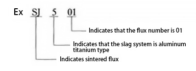
65. Preparation method of sintered flux brand?
According to the regulations in the product sample of welding materials, the sintered flux is represented by the letter SJ followed by three digits:
1) The first digit indicates the slag system of flux slag, as shown in Table 8.
Table 8 first digit series of sintered flux brand
Flux brand
Range of main components of slag (number of quality classification types) (%)
SJ1 ×× SJ2 ×× SJ3 ×× ST4 ×× sJ5 ×× SJ6 ××
Calcium fluoride type; High aluminum type; Silicon calcium type; Silicon manganese type; Aluminum titanium type; Other types
2) The second and third digits represent different brands of flux in the same slag system type, which are arranged in the order of 01, 02 and „.
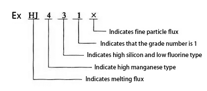
66. Preparation method of melting flux brand?
According to the regulations in the product sample of welding materials, the melted flux is represented by the letter HJ followed by three digits:
1) The first digit indicates the content of MnO in the flux, and its series arrangement is shown in Table 9.
Table 9 first digit series of melting flux brand
Flux brand
Flux Type
Mass fraction of MnO (%)
H order 1 ×× H2 ×× H Ding 3 ×× H Ding 4 ××
No manganese; Low manganese; Medium manganese; High manganese
<22~51
2) The second digit indicates the content of SiO2 and CaF2 in the flux, and its series arrangement is shown in table 10.
Table 10 second digit series of melting flux brand
Flux brand
Flux Type
Mass fraction of si0caf (%)
× one × HJ × two × H × three ×× 4XHJ × five × H Ding × six × HJ × seven × HJ × eight × H × nine ×
Low silicon and low fluorine; Medium silicon and low fluorine; High silicon and low fluorine; Fluorine in low silicon; Medium silicon and fluorine; Fluorine in high silicon; Low silicon and high fluorine; Medium silicon and high fluorine; other
3) The third digit indicates different grades of the same type of flux, which are arranged in the order of 0, 1, 2 and „. 4) When two particle sizes are produced for the same brand of flux, in the case of fine particles (the particle size of flux is
0.45 ~ 2.4mm) flux brand followed by“ ×” Word.
67. Performance and application of sj501 flux?
SJ501 is a sintered acid flux with a chemical composition shown in Table 11. The power supply is suitable for both AC and DC welding. When DC welding is used, reverse connection is adopted and the maximum welding current can reach 1200A. The color of the flux is silver white. It has strong resistance to porosity during high-speed welding and is not sensitive to a small amount of rust or high-temperature oxide film.
SJ501 is suitable for welding low-carbon steel and some low-alloy steel structures using H08A and H08MnA welding wires. It is also ideal for multi-wire rapid welding, particularly for double-sided single-pass welding.
Table 11 chemical composition (mass fraction) of SJ501 (%)
Si0+Ti0
Al2O3+MnO
CaF2
S
P
30
59
8.8
0.039
0.041
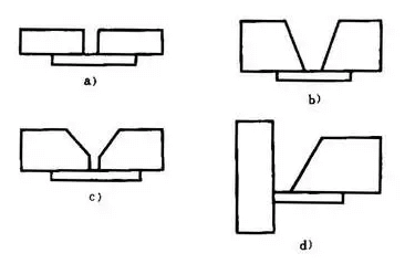
68. What are the common forms of pad joints? What are its advantages and disadvantages?
A backing plate, made of the same composition as the base metal, is placed at the back of the groove to ensure a fully welded joint during the welding process without burning through the root.
This type of joint is known as a backing plate joint, and common forms of the backing plate include: I-shaped belt backing plate groove, V-shaped belt backing plate groove, Y-shaped belt backing plate groove, single-sided V-shaped belt backing plate groove, as shown in Figure 6.
a) I-shaped groove with backing plate
b) V-shaped groove with backing plate
c) Y-shaped groove with backing plate
d) Single sided groove with backing plate
The operation skills required for base plate joint welding are simpler and easier to master compared to single-sided welding and double-sided forming.
This technique is often used in situations where welding on the back is not feasible, such as in the circumferential seam of small-diameter cylinders or jacketed containers.
However, a disadvantage of this method is that if the ellipticity of the base plate and the cylinder is inconsistent, there may be a gap when they are assembled together. During welding, molten slag may not float up and could result in slag inclusion.
The JB4708-92 welding procedure qualification for steel pressure vessels stipulates that the bending angle of single-sided welding with backing can be based on the bending angle standard of double-sided welding.
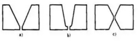
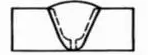
69. Compare the advantages and disadvantages of Y-shaped groove, U-shaped groove with blunt edge and double Y-shaped groove?
When the thickness of the weldment is the same, the geometry of the three grooves is shown in Fig. 5.
a) Y-groove b) U-groove with blunt edge c) Double Y-groove
(1) Y-groove
1) Groove surface processing is simple.
2) It can be welded on one side without turning over.
3) When the space area of welding groove is large, there are many filling materials and the thickness of weldment is large, the productivity is low.
4) Large welding deformation.
(2) U-shaped groove with blunt edge
It can be welded on one side without being turned over.
When the welding groove’s surface area is large, the amount of filler material required is small, and the thickness of the welded material is substantial, resulting in higher productivity than the Y-shaped groove.
Welding deformation is more significant for larger materials.
The difficulty in processing the root radius of the groove surface limits the popularity and application of this groove.
(3) double Y-shaped groove
Double-sided welding requires the weldment to be turned over during welding, but the welding deformation is minimal.
Although the processing of the groove surface is slightly more complex than that of a Y-shaped groove, it is simpler than that of a U-shaped groove with a blunt edge.
The groove area is between a Y-shaped groove and a U-shaped groove with a blunt edge, resulting in higher productivity than a Y-shaped groove and less filling material required than a Y-shaped groove.
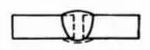
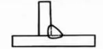
70. Try to describe the representation of supplementary symbols in weld symbols?
Supplementary symbols are used to supplement some characteristics of welds, as shown in table.
Name
Sketch Map
Symbol
interpretative statement
Symbol with backing plate
Indicates that there is a backing plate at the bottom of the weld
Three side weld symbol
Indicates that there are welds on three sides
Surrounding weld symbol
Indicates the weld around the weldment
Field symbol
Indicates welding on site or on site
Tail coincidence
The welding process and method can be marked with reference to gb185-85
71. What are weld symbols? How many parts does the weld symbol consist of?
The symbol on a drawing that indicates the welding method, weld form, and weld size is known as a weld symbol.
As per the representation of weld symbols outlined in GB324-88, a weld symbol typically consists of a basic symbol and a leader. Additionally, auxiliary symbols, supplementary symbols, and weld size symbols can be included as needed.
72. Describe the type of weld?
The joint formed in the weldment after welding is called weld.
According to the combination form, welds can be divided into butt welds, fillet welds, plug welds and end welds.
(1) Butt weld
The welds that make up the butt joint are called butt welds. Butt weld can be formed by butt joint or T-joint (cross joint), which refers to the weld with zero weld leg after full penetration welding after beveling.
(2) Fillet weld
The joint surface of the two weldments that are welded together can be welded in a straight or close-to-straight manner. Additionally, when the weld is made up of both butt weld and fillet weld, it is referred to as a combined weld.
A combined weld is created when a T-joint (cross joint) is beveled and welded with full penetration, resulting in a weld with a certain weld leg.
A butt weld is created in a groove, while a fillet weld is used to connect two weldments outside of the groove.
(3) Plug weld
It refers to the weld that fills the round hole formed by overlapping two weldments, one of which is opened with a round hole, and then welded in the round hole
(4) End weld
Welds forming termination joints.
73. Describe the influence of welding process parameters on weld shape?
During welding, the general name of various physical quantities (such as welding current, arc voltage, welding speed, linear energy, etc.) selected to ensure welding quality is welding process parameters.
The influence of process parameters on weld shape is as follows:
(1) Welding current
When other conditions remain unchanged, with the increase of welding current, the weld thickness and reinforcement increase, while the weld width remains almost unchanged (or slightly increased).
(2) Arc voltage
When other conditions remain unchanged, the arc voltage increases, the weld width increases significantly, and the weld thickness and reinforcement decrease slightly.
(3) Welding speed
When other conditions remain unchanged, an increase in welding speed results in a decrease in weld width, weld thickness, and reinforcement.
Welding current, arc voltage, and welding speed are the three main welding process parameters during welding.
When selecting these parameters, proper coordination among the three should be considered to obtain a weld with good shape and meet the required standards.
74. What are the technical requirements for butt welding of weldments?
The requirements for butt joints of weldments are as follows:
1. When butting steel plates with different thicknesses, a significant difference in thickness between the plates on both sides can cause a considerable change in the section at the connection after welding. This change can lead to severe stress concentration.
Therefore, for critical welded structures such as pressure vessels, thick plates should be thinned. As per relevant technical standards, when the thickness of the thinner plate is ≤ 10mm and the thickness difference between the two plates exceeds 3mm, or when the thickness of the thinner plate is > 10mm and the thickness difference between the two plates is greater than 30% of the thickness of the thinner plate or more than 5m, the edge of the thick plate must be thinned. The thinned length should be greater than or equal to 3 times the thickness difference.
2. When a straight-line weldment is butted with a curved weldment, the weld is just at the junction, leading to significant welding stress and becoming the weak surface of the entire structure. Therefore, the curved weldment at the butt joint should have a straight section so that the weld is in the flat butt position.
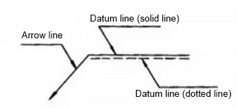
75. Try to describe the representation method and application of the leader in the weld symbol?
The leader is generally composed of a leader with an arrow (hereinafter referred to as the arrow line) and two datum lines (one is a solid line and the other is a dotted line), as shown in Fig. 17.
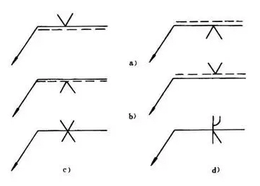
When using the leader, it shall match with the basic symbol:
If the weld is on the arrow side of the joint, mark the basic symbol on the solid line side of the datum line, as shown in Figure 18a.
If the weld is on the non-arrow side of the joint, mark the basic symbol on the dotted line of the reference line, as shown in Figure 18b.
When marking symmetrical welds and double-sided welds, dotted lines may not be necessary, as shown in Figure 18c and Figure 18d.
a) The weld is on the arrow side of the joint
b) The weld is on the non arrow side of the joint
c) Symmetrical weld
d) Double side weld work
76. Try to describe the principle and quality standard of magnetic particle flaw detection.
Magnetic particle testing is a non-destructive testing method that utilizes the phenomenon of magnetic particles being attracted by the leakage magnetic field generated by surface defects in ferromagnetic materials when subjected to a strong magnetic field.
The principle of magnetic particle flaw detection involves local magnetization of the inspected weld, which results in magnetic lines of force passing through the weld.
For welds with the same section size and uniform internal materials, the distribution of magnetic lines of force is uniform. However, in the presence of defects such as cracks, pores, and slag inclusions on the surface or inside of the weld, the magnetic lines of force will bypass these areas with high magnetic resistance, causing bending, as shown in Fig. 5A.
At this point, magnetic particles are sprinkled onto the surface of the weld, and the magnetic force lines pass through the magnetic particles that are located on the surface defects, creating “magnetic flux leakage” and causing the magnetic particles to be adsorbed on the defect.
The size and position of the defect can be determined by examining the shape, number, and thickness of the adsorbed magnetic particles.
It is important to note that internal defects that are far away from the weld surface will not create magnetic flux leakage on the magnetic lines of force, and therefore, the magnetic particles will not be absorbed or accumulate, making the defects undetectable. The most common magnetic particles used in this testing method are ferric oxide (Fe3O4) and ferric oxide (Fe2O3).
Defects can be divided into three types according to shape:
(1) The length of a linear defect magnetic trace is more than three times its width.
(2) A circular defect magnetic trace is any defect magnetic trace that is not linear.
(3) A scattered defect magnetic trace refers to several defects in a certain area appearing at the same time.
Quality standard: according to the provisions of ZBJ04006-87 standard, the grade of defective magnetic trace is divided into 7 levels.
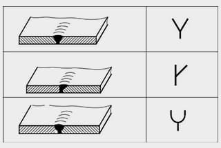
77. Describe the representation of basic symbols in weld symbols?
The basic symbol is a symbol representing the cross-sectional shape of the weld. Several common basic symbolic representations are shown in table.
Name
Sketch Map
Symbol
I-shaped weld
Y-shaped weld
Single side V-shaped weld with blunt edge
U-shaped weld with blunt edge
Back bead
Fillet weld
Plug weld
78. Principle of radiographic inspection and image characteristics of welding defects.
X-rays and Y-rays can be used for radiographic inspection, respectively.
When the rays pass through metal materials, part of their energy is absorbed, attenuating the rays. The attenuation is different depending on the thickness of the penetrating metal material, which may vary due to defects such as cracks, pores, incomplete penetration, or other imperfections that cause thinning of the material, or due to differences in volume and mass (such as slag inclusions).
Attenuation is more significant when passing through thick or large objects, resulting in weaker intensity on the substrate, lower sensitivity of the negative, and shallower blackness after development. Conversely, the blackness is deeper when attenuation is less.
By analyzing the images with different levels of blackness on the negative, defects can be clearly displayed.
79. Try to describe the principle and quality standard of ultrasonic flaw detection.
Ultrasonic flaw detection is a non-destructive testing method that uses ultrasound to detect internal defects in materials.
The principle of ultrasonic flaw detection involves finding defects by utilizing the difference in acoustic impedance (the product of material volume mass and sound velocity) between the defects in welds and normal tissues, as well as the reflection phenomenon of sound waves on heterogeneous interfaces with different acoustic impedance.
During flaw detection, a piezoelectric transducer in the probe emits pulse ultrasonic waves, which are transmitted to the weldment through an acoustic coupling medium (such as water, oil, glycerol, or paste).
After encountering the defect, the ultrasonic wave generates a reflected wave. Another similar or the same probe is then used to receive the reflected sound wave, which is converted into an electrical signal by the transducer.
The electrical signal is amplified and displayed on a fluorescent screen or printed on paper tape. The defect position can be determined based on the probe position and the propagation time of the sound wave (echo position on the fluorescent screen).
The amplitude of the reflected wave can provide an approximate evaluation of the size of the defect.
Quality standard: The probability of the ultrasonic beam being perpendicular to the defect plane increases with the number of directions of ultrasonic detection of welds, resulting in a higher detection rate of defects and more accurate evaluation results.
According to GB11345-89, the manual ultrasonic flaw detection methods and classification of flaw detection results for steel welds classify ultrasonic damage into three inspection levels: A, B, and C based on the number of detection directions of welds. The inspection quality increases from level A to level C, with level B being suitable for pressure vessels.
80. Why should the welding area be protected? How to protect?
The purpose of protecting the welding area is to prevent air from invading the droplet and pool and reduce the nitrogen and oxygen content in the weld metal.
There are three ways of protection:
⑴ Gas protection.
During gas shielded welding, a shielding gas (CO2, H2, Ar) is used to isolate the welding area from the surrounding air.
Slag protection, on the other hand, involves covering the molten pool’s metal surface with a layer of slag to prevent air contact. This method is commonly used in welding processes like electroslag welding and submerged arc welding.
Gas slag combined protection is another method that utilizes both shielding gas and slag to protect the molten metal simultaneously. This method is commonly used in manual arc welding.
As the founder of MachineMFG, I have dedicated over a decade of my career to the metalworking industry. My extensive experience has allowed me to become an expert in the fields of sheet metal fabrication, machining, mechanical engineering, and machine tools for metals. I am constantly thinking, reading, and writing about these subjects, constantly striving to stay at the forefront of my field. Let my knowledge and expertise be an asset to your business.
Welding symbols may seem like a foreign language, but mastering them is crucial for effective communication in the world of mechanical engineering. In this blog post, a seasoned mechanical engineer…
Ever wondered how skyscrapers stand tall or cars stay welded together? This blog uncovers the magic behind electric welding machines. Learn about top manufacturers like Lincoln Electric and Miller Welds,…
Have you ever wondered how the sleek cars, sturdy bridges, and advanced airplanes of today are built? This article explores six cutting-edge welding technologies that are revolutionizing manufacturing, from laser…
Have you ever wondered why some welded structures fail unexpectedly? This article explores the hidden forces at play—welding stress and deformation. Learn how these stresses impact strength, stability, and accuracy,…
Have you ever wondered how to calculate the consumption of welding rods accurately? In this blog post, we'll explore the methods and formulas used by industry experts to estimate welding…
Have you ever wondered about the art of welding and the different positions involved? In this fascinating blog post, we'll delve into the intricacies of welding positions, from flat to…
Ever wondered what "X-weld" or "tack-weld" means? Our latest article breaks down 292 crucial welding terms, offering clear definitions and practical examples. Whether you're a seasoned welder or just starting,…
Why does argon arc welding sometimes produce pores, and how can we fix it? Welding porosity, often caused by impurities, improper gas flow, or incorrect technique, can weaken welds and…
Imagine a machine that welds with precision, never tires, and enhances safety in industrial settings. This article explores the fascinating world of arc welding robots, detailing their components, operational procedures,…