Welding Techniques for Thick Plates: A Comprehensive Guide
Ever wondered how massive steel plates are seamlessly welded together? In this article, we’ll explore the intricate process of welding a 4810mm x 4810mm x 270mm steel sheet. You’ll learn about the methods, materials, and techniques used to ensure precision and quality in welding thick plates.
What process do you want to use to solve the problem of welding base metal with a thickness of 270mm, such as robot welding or narrow gap welding?
Next, let’s examine how to produce a 4810mm x 4810mm x 270mm sheet by performing a butt welding of 270mm Q235D steel plates.
1. Problems of welding large thick plates and measures to solve them
Requirements: The flatness requirements range from 8 to 10 mm to guarantee the material properties of the steel plate after welding.
(1) Number and Size of Welded Steel Plates
This is constructed using three steel plates, with widths of 1,900mm, 1,900mm, and 1,050mm, and lengths of 4,830mm, which are joined together.
To account for welding shrinkage, a margin of 9 mm was reserved. However, after production was completed, it was discovered that the shrinkage was between 10 and 12 mm. Despite this, the machining allowance of 25-30 mm with a maximum error of 3 mm does not affect its use in processing.
(2) Welding Method and Groove Type
Common thick plate welding methods include electro-slag welding, submerged arc welding, gas-shielded welding, and electrode arc welding.
Given the conditions of the enterprise and the efficiency of various welding methods, the welding method chosen was CO2 gas-protected backing welding with submerged arc welding and covering the surface.
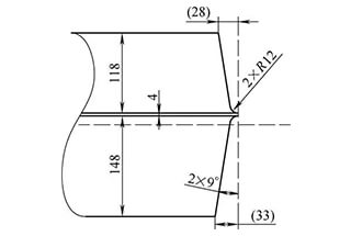
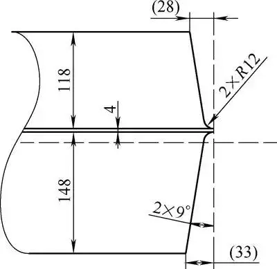
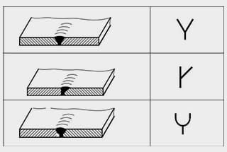
The groove forms of thick plates are mostly of type Ⅰ, X-shape, and U-shape, among others. After comprehensive comparison, the U-shaped groove was selected.
To ease the root clearing process, an asymmetric U-shaped groove was chosen. To ensure welding quality, the production of the groove must be completed through machining and must guarantee a size and surface roughness value of 12.5μm.
(3) Pre-Welding Test
To ensure welding quality, a 1m long steel plate with a thickness of 200mm was used for a welding test, which served not only to train the welders but also to identify any shortcomings in the actual operation process.
During the bottom welding test, it was observed that the opening at the unwelded end did not change significantly as the welding end was moved to the other end.
An analysis of the main causes of cracking was conducted as follows:
① Hardening Tendency
The material being used is Q345D steel with a carbon content upper limit of 0.18%; wP, S ≤ 0.03%.
With low hardening tendency and good weldability, this is not considered the main cause of cold cracks.
② Hydrogen’s Function
The welding materials used were strictly dried and the workshop environment was kept dry.
Even if a small amount of hydrogen remains in the weld during welding, the content is low and is not considered the main cause of cold cracks.
③ Uneven temperature distribution in the thickness direction during welding can lead to large lateral compression plastic deformation;
Uneven shrinkage in the thickness direction when cooling after welding can easily cause angular deformation between the two connectors.
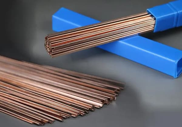
The selection principle for welding materials is that the alloy composition and strength performance of the weld metal should meet the lower limit specified by the base metal standard or reach the minimum performance index specified by the product technical conditions.
Therefore, it was decided to use THQ-50C welding wire with a diameter of 1.2mm, H10Mn2 submerged arc welding wire with a diameter of 4mm, and SJ101 flux (preheated for more than 4 hours at 100°C before welding). The welding parameters are as follows.
Note: The temperature between the layers in the welding area ranges from 120 to 180℃.
Lastly, reverse deformation is employed to control the deformation that occurs during the welding process.
In the welding construction process, due to the reverse deformation caused by welding, it is necessary to promptly turn the workpiece and weld the other side, allowing for cyclic operation to control the deformation.
(5) Heat Treatment
Preheating of the workpiece is a must before welding, and it is crucial to ensure even heating of the workpiece.
After several trials, it was decided to drill several evenly spaced holes on one side of a 4.8 m long pipe.
The pipe was then sealed with a gas-cutting nozzle that was welded to the pipe, and heated through gas ignition.
Two pieces were made so that both sides of the weld could be heated simultaneously.
At the end of the welding process, a large amount of welding residual stresses are generated inside the workpiece.
To prevent delayed cracking and deformation during processing, in-furnace de-stressing annealing must be performed after welding.
2. Implementation
Place the sheet material 1 to 1.2 meters above the ground, with an anti-deformation angle of 1 to 1.5 degrees and a butt gap of approximately 2mm.
Before welding, the 200mm area on either side of the reverse side of the weld will be simultaneously heated at multiple points to ensure uniform preheating temperature. The preheating temperature of the forward side should be between 90 to 120°C.
The side with the large groove will be welded first, using CO2 gas-shielded arc welding for the base.
At this time, the deformation of the farthest part of the control plate must be measured (with a minimum of 4 measuring points).
When the deformation of the workpiece is between 1 and 1.2 degrees (calculated as A), i.e., the measurement point is above the plane value of ≤ A, the workpiece must be turned over.
It is important to note that when welding on a large thick plate, the workpiece must be flipped and welded on both sides of the weld concave rib plate to prevent lifting when cracks occur.
The width of the control submerged arc filler weld should be less than 18mm to reduce defects. The weld width should be the same.
After flipping the workpiece, carbon arc gouging is necessary to remove the bottom weld, reveal the weld metal, and smooth the surface. Then, submerged arc welding can commence.
During the welding process, the deformation of the farthest side plate will be continuously measured.
When the reverse deformation reaches 0 degrees, the concave ribs at the weld will be removed, leaving only three evenly spread weld ribs. When the reverse deformation reaches (A-5) mm, the workpiece will be flipped again.
After the workpiece has been turned and secured, the weld ribs will be removed, and the deformation of the plate will be observed (the observation values are small, about 2mm).
Submerged arc welding will then start, and when the reverse deformation is less than or equal to 10 mm (measured as described above), the workpiece will be turned again.
This process should be accompanied by a high-temperature ultrasonic flaw detection, if available, to reduce the amount of rework required for final defects.
After the workpiece is turned, submerged arc welding will be performed while controlling the reverse deformation to within 5mm.
The workpiece will be flipped and welded on the other side until the entire welding process is complete.
After welding, the workpiece will be kept warm for 6 hours.
After natural cooling, the weld surface will be smoothed, ultrasonic testing will be conducted, and the entire piece will undergo stress relief annealing in the furnace at 620℃ for 10 hours.
During annealing, the deformation of the large plate due to its own weight should be taken into consideration, and methods such as self-weight and external gravity can be used to flatten the plate.
Once the welded parts have undergone stress relief annealing and cooled to room temperature, the welding defects and flatness will be tested, and the next steps will be carried out if requirements are met.
The other steel plate will be welded to the welded steel plate using the same welding method and steps as described above.
After the overall welding is complete, the weld will be kept warm for 6 hours, naturally cooled, and subjected to ultrasonic testing. Then, the entire piece will undergo stress relief and annealing again.
As the founder of MachineMFG, I have dedicated over a decade of my career to the metalworking industry. My extensive experience has allowed me to become an expert in the fields of sheet metal fabrication, machining, mechanical engineering, and machine tools for metals. I am constantly thinking, reading, and writing about these subjects, constantly striving to stay at the forefront of my field. Let my knowledge and expertise be an asset to your business.
Welding thick-walled titanium alloys poses significant challenges but holds immense value in industries such as aerospace and marine equipment. This article explores advanced fusion welding technologies like non-consumable electrode gas…
What if you could enhance your welding precision with just a few adjustments? This article delves into the crucial relationship between welding current, wire diameter, and plate thickness in CO2,…
Welding symbols may seem like a foreign language, but mastering them is crucial for effective communication in the world of mechanical engineering. In this blog post, a seasoned mechanical engineer…
Have you ever wondered how the sleek cars, sturdy bridges, and advanced airplanes of today are built? This article explores six cutting-edge welding technologies that are revolutionizing manufacturing, from laser…
Have you ever wondered how to calculate the consumption of welding rods accurately? In this blog post, we'll explore the methods and formulas used by industry experts to estimate welding…
Have you ever wondered about the art of welding and the different positions involved? In this fascinating blog post, we'll delve into the intricacies of welding positions, from flat to…
Ever wondered what "X-weld" or "tack-weld" means? Our latest article breaks down 292 crucial welding terms, offering clear definitions and practical examples. Whether you're a seasoned welder or just starting,…
Welding aluminum alloys presents unique challenges due to their low melting point and high thermal conductivity. This article dives into various welding methods, such as TIG, MIG, and plasma arc…
Yaskawa welding robots, during their welding operations, have their pool temperature dependent on numerous factors. The correct operation of these robots by technical personnel encompasses elements such as wire angle,…