Boosting Bolt’s Fatigue Strength: Top Strategies Revealed
How can we make bolts last longer under stress? This article explores methods to boost the fatigue strength of bolts, essential for preventing failures in high-stress environments like engines. Learn about material selection, heat treatments, and design techniques that can significantly extend the life of your bolts. Read on to discover the key strategies that ensure your fasteners remain reliable even under the toughest conditions.
In modern equipment, bolts often operate under variable loads. For instance, a type of internal combustion engine cylinder head bolt works in a harsh environment under repeated tension.
The structure does not allow for an increase in bolt size, necessitating an enhancement of its strength and tensile fatigue resistance.
In other words, there are higher demands for the tensile fatigue life of such bolts.
1. Fatigue Standards for Threaded Fasteners
Given the diversity of user requirements and varying operating environments for fasteners, it is essential to establish and select life expectancy indicators under standardized environments, where load conditions are the most significant factor.
1.1 Load Conditions
The load conditions referred to here are the maximum and minimum load values applied to the bolt during fatigue testing.
Currently, both ISO and our national standards for bolts with a σb≥1200MPa rating set the maximum load value as 46% of the bolt’s minimum tensile failure load— the K value (load factor).
The standards specify minimum failure load standard values for bolts of different diameters.
These values serve as the basis for static tensile strength acceptance and the basis for fatigue testing load (maximum fatigue tensile test load = minimum tensile load × load factor K).
For example, for alloy steel hex head bolts, the K value is set at 0.46.
The minimum load in the fatigue tensile test is determined by the load ratio R. R = minimum load / maximum load, R = 0.1.
1. 2 Lifespan Indices
Under the aforementioned load stipulations, there’s a unified lifespan index. That is, among the prescribed sample specimens, the minimum cycle count is no less than 4.5×10⁴.
Any count exceeding 13×104 in the specimens is considered as 13×104 for averaging purposes.
2. Tensile Fatigue Life of Threaded Fasteners
2.1 Selection of Bolt Materials and Heat Treatment
According to related standards in China (such as GB/T 3098.1—2000), fatigue performance requirements are only specified for bolts with σb≥1200MPa.
The main reason for imposing fatigue performance requirements on high strength steel is that while its strength is enhanced, its material plasticity reserve is markedly inferior to medium and low strength steel.
Comparing this requirement with nickel-based alloys and titanium alloys, which have higher strength and good plasticity reserve, is obviously inappropriate. For instance, 40CrNiMo, 30CrMnSi, etc.
If we choose a higher strength alloy steel material like the American INCONEL 718 alloy, which can have a strength above 1600MPa, it will demonstrate high life values during fatigue testing under typical load conditions. Let’s take the M6 bolt as an example.
If the fatigue test load specified by the standard is 11.01kN, and the static tensile failure load is 23.93kN, while the actual static tensile failure load of INCONEL 718 alloy can reach up to 35kN.
If we still use 11.01kN as Pmax for the fatigue test, it would only be equivalent to 31% of the static tensile failure load, naturally, its life value will be higher.
However, for high-strength materials like 30CrMnSiNi, their notch sensitivity is extremely high, and the life values during tensile fatigue tests are very low. They are not suitable for use in threaded components that require tensile fatigue resistance.
While certain materials can match the static tensile failure load of alloy steels like 30CrMnSi, they fail to meet the standard requirements in fatigue life tests at the same load level, such as titanium alloy Ti6Al4V.
To align their fatigue life value with 30CrMnSi and other alloy steels, the load level must be reduced to 40% (that is, taking K value at 40%) and for other types of titanium alloys (like Ti21523), K should be reduced to 36%.
However, this approach is problematic: typically, titanium alloy bolts with equivalent static strength have better fatigue performance than similar steel bolts.
This is a basic understanding of the properties of different materials. In this case, the K value for titanium alloy bolts can certainly be higher than 0.46, and definitely not as low as 0.36.
Therefore, for bolted joints requiring high static tensile strength and higher tensile fatigue life, the correct material selection should be given proper attention.
Fatigue fracture and delayed fracture are two main reasons for the failure of mechanical components, which is a confusing concept. Delayed fracture in bolts is often due to a hydrogen-induced damage behavior caused by surface plating, which is basically unrelated to fatigue fracture.
Generally speaking, when the tensile strength of steel is about 1200MPa, both the fatigue strength and resistance to delayed fracture increase with the increase in strength and hardness.
However, when the tensile strength exceeds approximately 1200MPa, the fatigue strength no longer continues to increase, and the resistance to delayed fracture drops sharply instead.
Most of the steel used in mechanical manufacturing is medium carbon alloy steel, used in a tempered state, with a tensile strength mostly between 800 and 1000MPa.
Increasing its strength is not difficult, but the greatest challenge lies in resolving the short lifespan issue following the strength enhancement.
Fatigue failure and delayed fracture problems are the primary barriers to the high-strength and long-life of steel used in mechanical manufacturing.
Heat treatment is a critical factor, particularly the tempering during the quenching process of high-strength bolts. In the high-temperature tempering zone, impurities such as sulfur and phosphorus are likely to form.
When these impurities accumulate on the grain boundaries, they can lead to brittle fracture, especially when the hardness exceeds 35 HRC, the tendency for brittleness significantly increases.
2.2 Techniques to Improve Fatigue Life
Before strengthening, the probability of tensile fatigue failure in threaded fasteners is as follows: 65% of failures occur at the first engagement with the nut, 20% of failures occur at the transition between the thread and the shank (although this statement is broadly accurate, it must be noted that the fundamental cause of fatigue failure at these points is still due to high stress concentration), which is at the end of the threads, and 15% of failures occur at the transition radius between the bolt head and the shank, as shown in Figure 1.
It should be emphasized that these statistics are based on the condition that the metal flow lines of the entire fastener are not damaged.
Figure 1: Requirements for Bolt Head Sink Angle and Stress Analysis of Thread Flanks
To improve tensile fatigue life, measures can be taken in both bolt shape and process, with the most effective methods currently as follows.
2.2.1 Use of MJ Threads (i.e., reinforced threads)
The primary difference between MJ threads and regular threads lies in the minor diameter (d1) and radius (R) of the external threads, as shown in Figure 2.
The main feature of MJ threads is a larger minor diameter (d1) than regular threads, with an increased root fillet radius, reducing stress concentration in the bolt.
Specific requirements for R are given (Rmax=0.18042P, Rmin=0.15011P, P being the pitch), while regular threads do not have such requirements and can even be straight. This significant change greatly enhances the tensile fatigue performance of the minor diameter.
Currently, MJ threads are widely used in aerospace bolts.
Figure 2: Transition Fillet
2.2.2 Improving Thread Fatigue Performance
By using the thread rolling process, due to the effects of cold work hardening, there is residual compressive stress on the surface, allowing the directional flow of internal metal fibers in the bolt to be rational and unbroken.
Consequently, the fatigue strength can be 30% to 40% higher than that of threads machined by turning.
If the thread is rolled after heat treatment, it strengthens the surface of the part and creates a residual stress layer, which can enhance the surface fatigue limit of the material by 70% to 100%.
This process also has advantages such as high material utilization, high production rate, and low manufacturing cost. Table 1 shows the fatigue life values under different process methods.
The test bolt material is 30CrMnSiA, the bolt standard is GJB 121.2.3, and 6×26 (i.e., MJ6) is tested for tensile fatigue according to the test method, with test fatigue load: Pmax=10.1kN, Pmin=1.01kN. The results are shown in Table 1.
Table 1: Fatigue Life (Number of Cycles) Under Different Process Methods
Test No.
A
B
C
D
Before heat treatment, cold roll the threaded screw.
Before heat treatment, do not cold roll the threaded screw.
After heat treatment, cold roll the threaded screw.
After heat treatment, do not cold roll the threaded screw.
1
17800
13800
130000
130000
2
11900
11600
130000
93700
3
13400
17400
130000
70400
4
20100
8700
130000
103300
5
15500
18100
130000
98600
6
18000
15200
130000
51300
1
14100
11300
130000
95800
8
8400
12000
130000
88100
9
18200
17300
127600
From Table 1, it is evident that the tensile fatigue resistance of the fillet r at the turning point of the cold-rolled threaded bolt, post heat treatment, is optimal (refer to Figure 1). The requirements for the value of r in cold extrusion are not stringent. The technical specifications only stipulate an upper limit for deformation.
2.2.3 Strict Control of Final Dimensions
As demonstrated in Figure 1, the transition area between the bolt thread and the smooth rod is one of the significant sources of fatigue. Strict control of the final dimensions to shape the transition area is a crucial measure to enhance the fatigue life in this region.
Therefore, during the design and manufacture of thread rolling wheels, it is imperative to strictly grind the ends according to the standards, and strictly control the thread rolling position during the process.
Specific measures can include a larger transition fillet as shown in Figure 3a, the creation of unloading structures as shown in Figures 3b and 3c, and cutting a tool withdrawal groove at the end of the thread can also reduce stress concentration (the schematic diagrams in Figures 3b and 3c can be misleading. Increasing the fillet in the transition area indeed helps alleviate local stress concentration).
Cold extrusion of the fillet r at the bolt’s turning point, as shown in Figure 1, can enhance the tensile fatigue life at this point. As Table 1 shows, if only the strengthening measures in 2.2.1, 2.2.2, and 2.2.3 are taken, fatigue fractures will exclusively occur at the bolt’s turning point.
Therefore, cold extrusion strengthening of fillet r is one of the important measures to improve the overall tensile fatigue life of the bolt.
2.3 Avoid Generating Additional Bending Stress
Due to poor design, manufacturing, and assembly, eccentric loading of bolts may occur. Eccentric loads can induce additional bending stress in the bolts, significantly reducing their fatigue strength. Therefore, appropriate structural and process measures should be taken to prevent the generation of additional torque.
(1) The angle of the bolt’s countersink should be accurate, allowing only a positive deviation of 0° to 0.5°, with no negative deviation allowed.
(2) The bolt’s bearing surface should be flat and perpendicular to the bolt hole axis.
(3) For assembly holes on the workpiece, such as those for hexagonal heads, the chamfer of the hole should comply with international standards.
2.4 Preload Assembly
The preload is one of the most critical issues in threaded connections. Theory and practice have shown that with the rigidity of the bolt and the joined parts held constant, appropriately increasing the preload significantly enhances the resistance to tensile fatigue. This is why the bolt preload stress can reach up to 0.7 to 0.8 of the yield stress (σs).
Therefore, accurately controlling the preload and maintaining its value are crucial. The preload magnitude is controlled by a preset torque wrench or preload indicating washers.
The required preload varies under different conditions, and commonly, empirical formulas based on prior experience are used for estimating preload.
For general mechanical preload: σp = (0.5 to 0.7)σs; for high-strength connections: σp = 0.75σs (this is the yield limit). This method of expressing preload contradicts the aforementioned 46% approach.
Recently, a new method of bolt connection has been developed, which involves preloading the bolt to the yield point, allowing the bolt to work within the plastic region. For more details, refer to the paper “Plastic Screw Domain Connection” by Ichiro Maruyama, published in “Mechanical Research,” Volume 40, No. 12, 1988. For critical preloaded connections against fatigue, fatigue life tests under different preloads should be conducted to determine the correct and usable preload values.
3. Conclusion
Through experimental data and practical experience, the document proposes several specific measures to enhance the tensile fatigue strength of bolts, addressing aspects of material selection, machining, and assembly.
Some of these measures have proven their efficacy in practical applications, while certain empirical data and conclusions await further theoretical exploration and validation.
In summary, comprehensive measures must be adopted to improve the tensile fatigue strength of bolts; no single measure can fulfill the overall need for fatigue resistance.
As the founder of MachineMFG, I have dedicated over a decade of my career to the metalworking industry. My extensive experience has allowed me to become an expert in the fields of sheet metal fabrication, machining, mechanical engineering, and machine tools for metals. I am constantly thinking, reading, and writing about these subjects, constantly striving to stay at the forefront of my field. Let my knowledge and expertise be an asset to your business.
Attention all mechanical engineers and manufacturing professionals! Are you struggling with pesky anodizing defects in your aluminum products? Look no further! In this blog post, we'll dive deep into the…
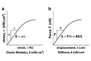
Ever wondered why some materials bend easily while others remain rigid? This blog dives into the fascinating world of elastic modulus and stiffness, unraveling their crucial roles in engineering. By…
Have you ever wondered what makes a perfect circle? In the world of mechanical engineering, roundness is a crucial concept that affects the performance and longevity of rotating components. This…
In today's fast-paced manufacturing world, efficient deburring is crucial. With numerous methods available, choosing the right one can be daunting. In this blog post, we'll explore various deburring techniques, from…
Have you ever wondered what keeps the world spinning smoothly? The unsung heroes behind the scenes are bearings. These small but mighty components play a crucial role in reducing friction…
Gears are the unsung heroes of the mechanical world, quietly working behind the scenes to keep machines running smoothly. But have you ever wondered what materials these critical components are…
This article explores the top 5 cooling tower manufacturers shaping our world. Learn how these companies innovate to keep industries running smoothly and efficiently. Get ready to uncover the secrets…
Have you ever wondered what keeps our gas systems running smoothly and safely? In this article, we explore top gas regulator manufacturers, uncovering their innovations and contributions to the industry.…
Ever wondered why connecting copper and aluminum wires is problematic? This article explains the risks associated with connecting these two metals due to their differing electrochemical properties, which can lead…