Understanding Bolt Fracture: Mechanisms and Factors
Have you ever wondered why bolts break and cause machinery failures? This article explores the critical factors behind bolt fractures, from design flaws to material issues. You'll learn how to…
Yield strength, a crucial yet often overlooked property, plays a vital role in materials selection. In this article, we’ll delve into the fundamentals of yield strength and explore its significance in mechanical engineering. Discover how this essential concept shapes the world around us and gain valuable insights from industry experts.
Yield Strength: It is the yield limit of a metal material when it yields, i.e. the stress that resists slight plastic deformation.
For metal materials without obvious yielding, the stress value that produces 0.2% residual deformation is specified as its yield limit, called the conditional yield limit or yield strength.
External forces greater than this limit will cause the permanent failure of the component and cannot be restored. For example, the yield limit of low-carbon steel is 207 MPa.
When external forces greater than this limit are applied, the component will undergo permanent deformation. If it is less than this, the component will return to its original form.
The traditional strength design method regards the yield strength as the standard for plastic materials, with the permissible stress [σ]=σys/n, where the safety factor n can range from 1.1 to 2 or more, depending on the situation.
For brittle materials, the tensile strength is taken as the standard, with the permissible stress [σ]=σb/n, and the safety factor n is generally taken as 6.
It should be noted that the traditional strength design method will inevitably lead to a one-sided pursuit of high yield strength for the material, but as the yield strength of the material increases, the fracture strength decreases and the risk of fracture increases.
The yield strength not only has direct practical significance, but also serves as a rough measure of some mechanical behavior and process performance of the material in engineering.
For example, as the yield strength of the material increases, it becomes more sensitive to stress corrosion and hydrogen brittle fracture; as the yield strength decreases, the cold forming performance and welding performance improve, and so on.
Therefore, the yield strength is an indispensable important index in material performance.
Stress
When an object deforms due to external factors (forces, humidity, changes in temperature, etc.), there are internal forces that interact between the various parts of the object. The internal force per unit area is called stress.
Those perpendicular to the cross-section are called normal stress or axial stress, and those tangent to the cross-section are called shear stress or cutting stress.
Strain
Strain refers to the relative deformation of an object under the action of external forces and non-uniform temperature fields, among other factors.
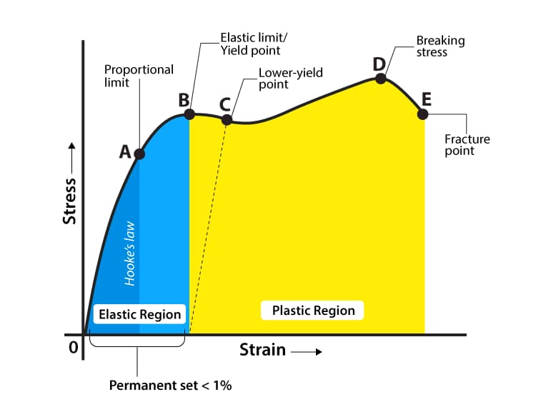
According to Hooke’s law, within a certain proportional limit range, stress and strain have a linear proportional relationship.
The corresponding maximum stress is called the proportional limit.
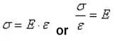
The ratio of stress to strain, denoted by E, is called the elastic modulus or Young’s modulus, and different materials have a fixed Young’s modulus.
Although stress cannot be directly measured, it can be calculated by measuring the strain caused by external forces.
Additional Information
Hooke’s law is a basic law in the theory of mechanical elasticity, which states that solid materials have a linear relationship between stress and strain (unit deformation) when subjected to stress.
Materials that satisfy Hooke’s law are called linear elastic or Hookean materials.
The expression of Hooke’s law is F=k·x or ΔF=k·Δx, where k is a constant, the rigidity (stiffness) coefficient of the object.
In the International System of Units, the unit of F is Newton, the unit of x is meter, and it is a deformation variable (elastic deformation), and the unit of k is Newton/meter.
The stiffness coefficient is numerically equal to the spring force when the spring is stretched (or shortened) by a unit length.
What are the types of stress?
Normal stress: The stress component perpendicular to the cross section is called normal stress (or axial stress) and is denoted by σ.
Normal stress represents the stretching and compression between adjacent cross sections within the part.
Normal strain: The normal strain at a point is the elongation along the direction of the normal force due to the normal stress distributed on the cross section in that direction.
Shear stress: The stress component tangential to the cross section is called shear stress or shear force, denoted by τ. Shear stress represents the sliding action between two parts.
Shear strain: The shear strain at a point is the change in angle between two perpendicular directions due to the shear stress distributed on the cross section. It is also known as shear deformation.
What are the types of strain?
There are mainly two types of strain: linear strain and angular strain. Linear strain, also known as normal strain, is the ratio of the increase in length (positive when elongated) of a small line segment in a certain direction to its original length.
Angular strain, also known as shear strain or shear deformation, is the change in angle (positive when decreased) between two perpendicular line segments due to the shear stress. It is expressed in radians.
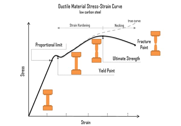
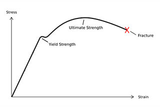
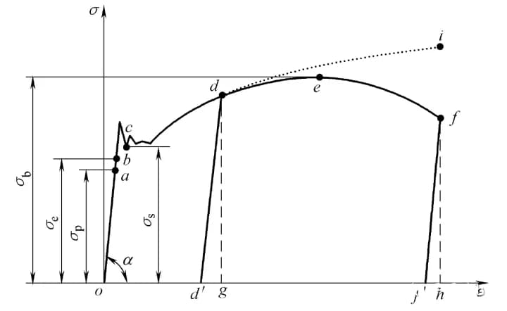
The stress-strain (σ-ε) curve diagram is shown in Figure 3.
Instead of the axial load F, the nominal stress σ = F / A0 is taken, and instead of the extension Δl, the engineering strain ε = Δl / l0 is taken.
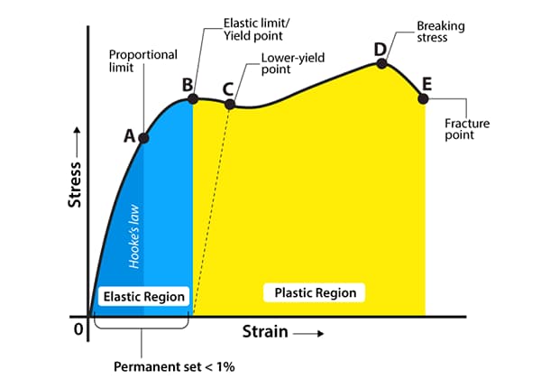
The stress-strain curve still has four stages. The meanings of each characteristic point are:
Stage o to a:
In the initial stage of stretching (or compression), the stress σ and strain ε are linearly related until point a.
At this point, the stress value corresponding to point a is called the proportional limit, represented by σp.
It is the maximum limit where stress and strain are proportional.
When σ≤σp, there is σ =Eε, also known as Hooke’s law, which indicates that stress and strain are proportional.
Therefore, E =σ / ε = tanα, where E is known as the elastic modulus or Young’s modulus, with units the same as σ. When the stress exceeds the proportional limit to reach point b, the σ-ε relationship deviates from a straight line.
If the stress is unloaded to zero at this point, the strain will also disappear (once the stress exceeds point b, a portion of the strain cannot be eliminated after unloading).
The stress defined at point b is called the elastic limit σe. σe is the ultimate limit value for only elastic deformation of the material.
Stage b to c:
After the stress exceeds the elastic limit, a phenomenon occurs where the stress increases very little or not at all, and the strain increases quickly.
This phenomenon is called yielding. The point where yielding begins corresponds to the yielding limit σs, also known as the yielding strength.
In the yielding stage, the stress does not change while the strain continues to increase, the material seems to have lost its ability to resist deformation, resulting in significant plastic deformation (if unloaded at this point, the strain will not completely disappear, and there will be residual deformation).
Therefore, σs is an important index for measuring material strength.
When a low-carbon steel specimen yields with surface polishing, the surface will have streaks at a 45° angle to the axis, due to relative sliding of the internal crystal lattice, known as slip lines.
Stage c to e:
After passing the yielding stage, if the specimen is to continue to deform, it must be loaded further, the material seems to have strengthened, and the c-e stage is the strengthening stage.
The highest point (point e) in the strain strengthening stage corresponds to the strength limit σb. It represents the maximum stress that the material can withstand.
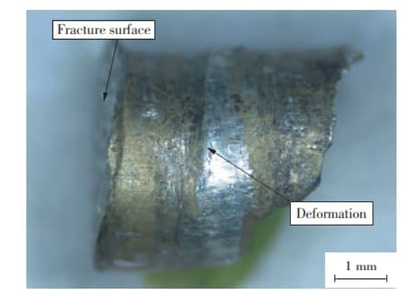
Stage e to f:
After passing point e, i.e., after the stress reaches the strength limit, the specimen undergoes a severe contraction locally, known as necking.
Then, cracks occur inside the specimen, the nominal stress σ decreases, and the specimen fractures at point f.
The yield strength (σs) and the tensile strength (σb) are important indicators of the strength of materials with good plasticity (such as low-carbon steel).
It should be noted that the nominal stress is used and the reduction in cross-sectional area accompanying the elongation deformation is not considered.
The tensile strength (σb) is only the nominal maximum stress that the material can withstand, not the actual maximum stress inside the material.
If the real area of the specimen at the time of fracture is used to measure, the actual maximum stress is the stress value corresponding to point i on the line d-i segment in the figure.
In engineering practice, for the sake of simplicity, practicality, and safety, the tensile strength (σb) is still used to represent the maximum stress that the material can withstand.
However, when simulating the nonlinear mechanical behavior of materials with a computer, the real stress-strain curve must be used.
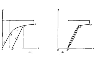
For metals without significant yielding phenomenon, their tensile strength under prescribed non-proportional extension or residual tensile strain can be measured.
For metals with significant yielding phenomenon, their yield strength, upper yield strength, and lower yield strength can be measured.
There are two methods to measure upper and lower yield strength: graphical method and pointer method.
Graphical Method
During the experiment, a force-jaw displacement graph is drawn using an automatic recording device.
The proportion of the force axis to the stress represented by each millimeter should be less than 10 N/mm2, and the curve should be drawn at least to the end of the yielding stage.
On the curve, the constant force Fe during yielding, the maximum force Feh before the first decrease in force during the yielding stage, or the minimum force FeL before the initial instantaneous effect are determined.
The yield strength, upper yield strength, and lower yield strength can be calculated using the following formulas:
Formula for yield strength calculation: Re = Fe/So; Fe is the constant force during yielding.
Formula for upper yield strength calculation: Reh = Feh/So; Feh is the maximum force before the first decrease in force during the yielding stage.
Formula for lower yield strength calculation: ReL = FeL/So; FeL is the minimum force before the initial instantaneous effect.
Pointer Method
During the experiment, when the pointer of the force gauge stops rotating at the constant force or the maximum force before the first return or the minimum force before the initial instantaneous effect, they correspond to the yield strength, upper yield strength, and lower yield strength, respectively.
The internal factors affecting yield strength are: bonding, microstructure, structure, and atomic nature.
A comparison of the yield strength of metals with ceramics and polymers shows that the effect of bonding is fundamental.
In terms of the impact of microstructure, there are four strengthening mechanisms that affect the yield strength of metal materials, which are:
(1) solid solution strengthening;
(2) strain hardening;
(3) precipitation strengthening and dispersion strengthening;
(4) grain boundary and sub-grain strengthening. Precipitation strengthening and fine-grained strengthening are the most commonly used means of improving the yield strength of industrial alloys.
Of these strengthening mechanisms, the first three mechanisms increase the strength of the material while also reducing plasticity.
Only refining the grain size and sub-grain can increase the strength and plasticity of the material.
The external factors affecting yield strength are: temperature, strain rate, and stress state.
As the temperature decreases and the strain rate increases, the yield strength of the material increases, especially the body-centered cubic metals are particularly sensitive to temperature and strain rate, which leads to low-temperature brittle fracture of steel.
The influence of stress state is also important. Although yield strength reflects the inherent performance of a material, the yield strength value is also different depending on the stress state.
The yield strength of a material commonly referred to is generally the yield strength under uniaxial tension.
| Steel grade | Mechanical property | Chemical composition | ||||||||
| yield strength | tensile strength | elongation | C | Si | Mn | S | P | |||
| MPa | kg/mm2 | MPa | Kg/mm2 | mm | Less than or equal to. | Less than or equal to. | Less than or equal to. | |||
| Q215A Q215B | 215 | 22 | 335-410 | 3442 | 31 | 0.09-0.15 | 0.03 | 0.25-0.55 | 0.050 0.045 | 0.045 |
| Q235A Q235B Q235C Q235D | 235 | 24 | 375-460 | 38-47 | 26 | 0.14-0.22 0.12-0.20 ≤0.18 ≤0.17 | 0.30 | 0.30-0.65 0.30-0.70 0.35-0.80 0.35-0.80 | 0.5 0.45 0.40 0.035 | 0.045 0.045 0.040 0.035 |
| Mn (Q345B) | 345 | 35 | 510-600. | 51.60 | 22 | 0.12-0.200 | .20-0.55 | 1.2-1.6 | 0.045 | 0.045 |
Yield strength testing is an important indicator of material strength characteristics and a critical indicator of material performance.
It is commonly used to evaluate material surface strength and plastic performance.
Yield strength testing methods are generally divided into two types: mechanical and non-mechanical.
Mechanical Yield Strength Testing:
This method generally involves three-point bending, tensile testing machine method, and compression method. The sample is placed between two supports and a constant force is applied using a mechanical device to determine the yield strength.
Non-mechanical Yield Strength Testing:
This method generally involves tensile, compression, and torsion methods. The sample is mounted on the testing instrument and a constant force is applied using a lever or computer control to determine the yield strength.
To improve the accuracy and precision of yield strength testing, it is generally necessary to perform multiple tests under necessary conditions and take the average value.
In all experiments, the treatment of the sample must be standardized and complete, and the sample must be maintained constant under the applied force. The final yield strength obtained is the maximum strength at which the material can bend under the applied load.
Through the study of this article, we learned what yield strength is, the basics of stress and strain, methods for determining yield strength, factors that affect yield strength, and applications of yield strength.
We hope this information will be helpful to everyone.
If there are any questions, please feel free to let us know in the comments section.

As the founder of MachineMFG, I have dedicated over a decade of my career to the metalworking industry. My extensive experience has allowed me to become an expert in the fields of sheet metal fabrication, machining, mechanical engineering, and machine tools for metals. I am constantly thinking, reading, and writing about these subjects, constantly striving to stay at the forefront of my field. Let my knowledge and expertise be an asset to your business.