During the bolt manufacturing process, bolt fracture occurred during the straightening process.
To identify the root cause of the bolt fracture, the broken bolt underwent macroscopic examination, chemical composition analysis, mechanical property test, metallographic structure analysis, and fracture analysis.
The results indicate that the bolt’s internal casting defects were not eliminated due to improper hot forging during the manufacturing process, leading to a reduced bearing capacity and cracking during the straightening process.
The task is to produce a batch of high-strength hexagonal bolts with specifications of M42 mm, material of 42CrMoA, and performance grade of 10.9.
The processing technology for bolts is as follows: annealing of raw materials → centerless turning → sawing → chamfering of flat end face → phosphating lubrication → shrinking rod → hot forging → chamfering of hexagon head → heat treatment (tempering) → straightening → rolling thread. The tempering process is treated by a mesh belt furnace.
During the straightening process, two bolts broke at approximately 1/2 of the screw axis (refer to Fig. 1).
The straightening process for the remaining bolts in this batch was stopped immediately after two bolts broke.
To identify the cause of the bolt fracture and prevent similar events from recurring, the author conducted a relevant inspection and analysis on the broken bolts.
1. Physical and chemical testing
1.1 Macro inspection
1.1.1 Macro analysis of fracture
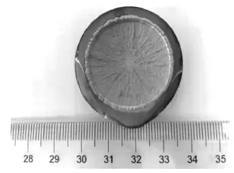
Both bolts were broken at about half of the screw in order to straighten the bending part, as depicted in Figure 1(a).
The fracture surface exhibits characteristics of brittle fracture as a whole. Radial stripes are visible on the fracture surface extending from the center to the periphery.
The outer layer of the fracture surface appears smooth and flat, indicative of brittle fracture.
No macroscopic plastic deformation or slag inclusion was detected on the surface of the fracture.
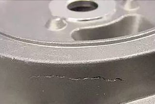
As shown by the arrow in Figure 2, cracks were found during the straightening process. The cracks initiated from the center and propagated towards the periphery, eventually resulting in bolt fracture.
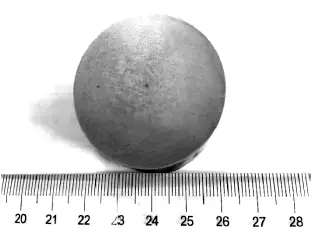
1.1.2 Macroscopic test
For low magnification inspection, a transverse sample should be taken 20 mm below the fracture surface of the broken bolt.
Numerous shrinkage cavities are discovered in the center of the bolt.
According to the inspection results, the general looseness is classified as Grade 1, the central looseness as Grade 2, and the general speckled segregation as less than Grade 1.
Refer to Figure 3 for details. No other macro defects, such as cracks, were detected.
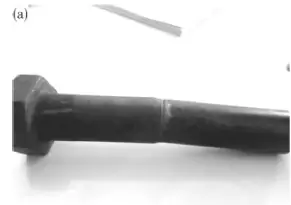
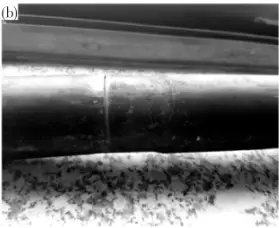
Fig.1 Broken bolt
1.2 Chemical composition analysis
Please take samples from approximately 20 mm near the fracture position of the bolt for chemical composition analysis.
For this task, we will be using the QSN750 direct reading spectrometer produced by OBLF in Germany. The chemical composition of the material will be tested to ensure it meets the requirements of GB/T 3077-1999 Alloy Structural Steel for the chemical composition of bolts of this material by spectral analysis. Please refer to Table 1 for the results.
To determine the oxygen, nitrogen, and hydrogen content of the sample taken from the broken bolt, we will be using the ONH-836 oxygen, nitrogen, and hydrogen analyzer from American Liko Company. According to the analysis results, the oxygen, nitrogen, and hydrogen content is 0.0011%, 0.0090%, and 0.0001%, respectively.
It’s worth noting that the levels of O, N, and H content are low.
Table 1 Chemical composition of broken bolt (w,%)
| Element | C | Si | Mn | P | S | Cr | Mo | Ni | Cu |
| Detection value | 0.42 | 0.34 | 0.69 | 0.010 | 0.004 | 1.10 | 0.20 | 0.04 | 0.02 |
| 0.43 | 0.33 | 0.70 | 0.010 | 0.006 | 1.07 | 0.20 | 0.04 | 0.02 | |
| 0.39 | 0.33 | 0.67 | 0.010 | 0.004 | 1.06 | 0.19 | 0.04 | 0.02 | |
| Standard value | 0.38-0.45 | 0.17-0.37 | 0.50-0.80 | 0.025 | 0.025 | 0.90~1.20 | 0.13~0.25 | <0.30 | <0.25 |
1.3 Mechanical properties
Select one bolt from the same batch for the tensile test.
The diameter of the tensile sample is 10mm, but it is not the actual bolt.
The HUT605A microcomputer-controlled electro-hydraulic servo universal testing machine from Wance Group is used to conduct the mechanical performance test.
Refer to Table 2 for the test results.
The hardness test is conducted on the metallographic sample of the broken bolt, and the test results are presented in Table 3.
There is no significant difference in the hardness between the surface and center of the bolt, and the results of the mechanical property test comply with the requirements of Mechanical Properties of Fasteners – Bolts, Screws and Studs (GB/T 3098.1-2010).
Table2 Test result of mechanical properties
| Properties | Tensile strength Rm/MPa | Yield strength Rel/MPa | Elongation A/% | Reduction of area Z/% |
| Detection value | 1069 | 970 | 14.6 | 53.5 |
| Standard value | ≥1040 | ≥940 | ≥9 | ≥48 |
Table 3 Test result of hardness
| Part | Surface/HBW | Core/HBW |
| Detection value | 333、329、337 | 321、329、329 |
| Standard value | 316~375 | |
1.4 Microstructure analysis
Metallographic samples were taken from the surface and core near the fracture of the broken bolt, and a metallographic inspection was conducted using an OLYMPUS-GX51 metallographic microscope.
Upon polishing, numerous holes were observed in the center, as depicted in Figure 3 (a), and no apparent abnormalities were found on the surface.
The microstructure of both the surface and core of the bolt was tempered sorbite.
The microstructure near the surface had a relatively small number of holes, as shown in Figure 3 (b).
The microstructure at the core had a relatively large number of holes, as shown in Figure 3 (c). No visible decarburization was found on the bolt’s surface, as demonstrated in Figure 3 (d).
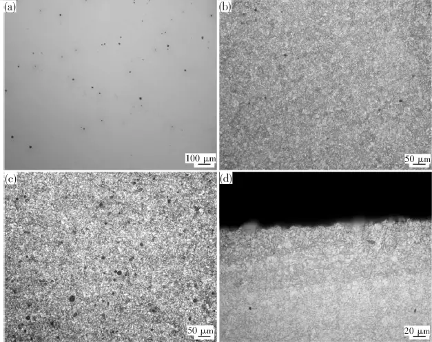
- (a)polish state;
- (b)near sunface;
- (c)core;
- (d)surface
Fig.4 Microstructure of bolt fractuire
1.5 Fracture morphology analysis
After ultrasonic cleaning, the IT300 scanning electron microscope was used to analyze the fracture morphology.
Observation of the SEM morphology on the radial area of the fracture surface shows that the fracture surface exhibits obvious cleavage fracture characteristics, and there are secondary cracks and a small number of holes at localized locations, as shown in Figure 4.
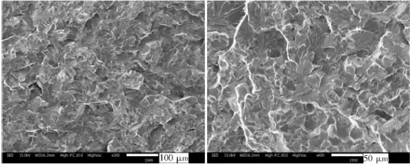
Fig.5 SEM morphologyy of fracture
2. Comprehensive analysis
The broken bolt’s chemical composition meets the standard requirements. The fracture exhibits transverse cracking, and macro analysis of the fracture surface indicates that it has brittle fracture characteristics.
The fracture surface has two parts: the crack initiation source area at the center of the fracture surface and the radial expansion area from the center to the periphery. There is no plastic deformation at the fracture edge, indicating brittle fracture characteristics.
At low magnification, a serious center looseness problem was found (center looseness level 2) on the test surface. During the casting process, the loose system gradually solidifies the molten steel from the surface to the center, and the columnar crystal area grows toward the center in the form of dendrites.
The first crystallized dendrites are relatively pure and have a high melting point. Segregated elements, gases, non-metallic inclusions, and a small amount of non-solidified molten steel are enriched between dendrites.
As the temperature decreases, the solidified part shrinks. When the non-solidified molten steel between dendrites is insufficient to supplement the gap, shrinkage cavities are formed. Loose defects are called general looseness. When porosity occurs in the central equiaxed area, it is called central porosity. The metallographic test results show tiny holes consistent with the low magnification test results.
Fracture analysis shows cleavage fracture morphology, and there are secondary cracks and a small number of holes on the fracture surface. The mechanical property test results meet the relevant standard requirements.
Therefore, the fracture exhibits transverse cracking, and the microstructure and mechanical property indexes meet the standard requirements. Furthermore, the bolt cracking was not caused by quenching and tempering since a mesh belt furnace was used in the process, and there was no untimely tempering.
The crack originated from the center and progressed outwards. The hydrogen content was insufficient to cause hydrogen embrittlement, and no hydrogen embrittlement feature (chicken claw pattern) was found in the SEM photos. Hence, the bolt cracking was not caused by hydrogen-induced delayed cracking.
The low magnification inspection revealed obvious central looseness at the bolt center, which is consistent with the crack source position of the fracture surface. The fracture system is transversely cracked, indicating the presence of axial tensile stress during cracking.
Therefore, based on the bolt manufacturing process, it can be determined that the bolt had central looseness due to raw material defects.
In the hot forging process, the casting defects were not eliminated, and under the continuous axial tensile stress in the rod shrinking process, the holes in the bolt initiated cracks that gradually expanded outward. The brittle cracks occurred during the straightening process, resulting in the failure of the bolt.
3. Conclusion
The root cause of the bolt fracture is the presence of casting defects (central looseness) in the bolt blank that were not eliminated during the hot forging process, resulting in a reduced bearing capacity of the bolt. The cracks then occurred under tensile force during the correction process.