How to Calculate Motor Power for Plate Rolling Machines
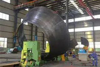
Have you ever wondered how a massive steel plate is bent into shape? In this article, we explore the fascinating mechanics behind plate rolling machines, revealing the forces and calculations…
Imagine trying to bend a thick steel plate into a perfect cylinder—how much force would you need? This article dives into the critical calculations for determining the load and power requirements for symmetrical 3-roll plate bending machines. You’ll learn about the force analysis needed for designing each part, the torque requirements, and the power needed for the main drive system. By understanding these calculations, you’ll gain insight into creating efficient and cost-effective plate bending machines.
The load on plate roll bending machines is substantial, necessitating high strength in their components. This is critical to ensure the machine’s durability and performance under heavy operational conditions.
In today’s competitive market, reducing the cost of plate rolls is crucial. This requires designing the machine with both accuracy and reliability to maintain quality while minimizing expenses.
To design a roll bending machine effectively, it is essential to first perform a comprehensive force analysis. This analysis provides the fundamental parameters needed for designing each part of the machine, ensuring that all components can withstand the operational stresses they will encounter.
Additionally, calculating the driving power of the main drive system is vital. This calculation is crucial for designing the main drive system and selecting an appropriate motor, ensuring the machine operates efficiently and effectively.
Therefore, performing a detailed force analysis and accurately calculating the driving power are critical steps in the design process of a roll bending machine.
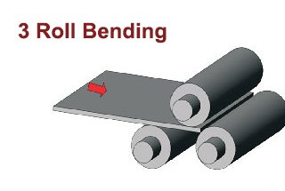
This post outlines a method for calculating the force capabilities of a symmetrical three-roll bending machine. This method can also serve as a reference for other types of plate rolling machines, providing a foundational approach to their design and optimization.
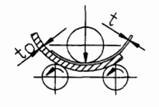
When the plate rolling machine is working, the steel sheet should be rolled into the steel pipe.
At this time, the stress of the material has reached the yield limit.
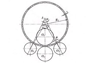
Therefore, the bending stress distribution on the tube section is shown below the figure (b), and the bending moment M of the section is:
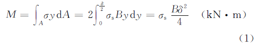
In the above formula,
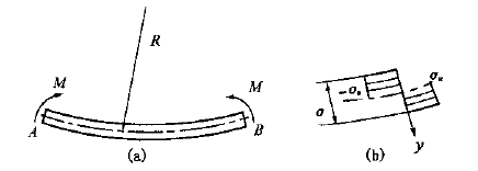
Fig.1 Stress distribution of roll bending
When considering the deformation of the material, there is reinforcement, and the reinforcement coefficient K is introduced to modify the equation (1), namely:
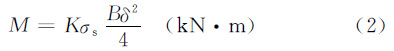
In the above formula,
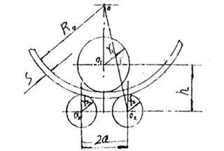
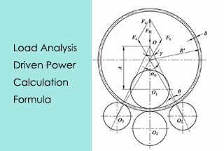
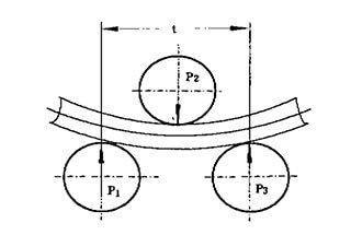
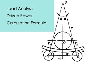
When rolling steel plate, the force condition is shown as below figure. According to the force balance, the supporting force F2 on the roll plate can be obtained via the formula:
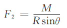
In the above formula,
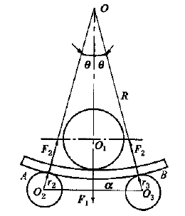
Fig.2 Force analysis of roll bending
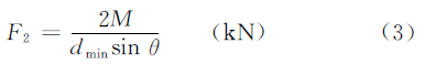
Considering that the thickness of the plate δ is far less than the minimum diameter of the rolling tube, the radius R of the neutral layer is around 0.5dmin, in order to simplify the calculation, the above equation can be changed to:
According to the force balance, the pressure force F1, which is generated by the upper roller, acting on the rolling plate is:

The lower roller of the plate rolling machine is the driving roller, and the driving torque on the lower roller is used to overcome the deformation torque Tn1 and the friction torque Tn2.
In the process of steel plate rolling, the deformation capabilities stored in AB section of the steel plate (see Fig 1a and Fig 2) is 2Mθ, the costed time is 2θR/V (V is rolling speed).
The ratio is equal to the power of deformation torque Tn1, namely:

Therefore,

The friction torque includes the rolling friction torque between the upper and lower roller and the steel plate, and the sliding friction torque between the roller neck and the shaft sleeve, which can be calculated as follows:
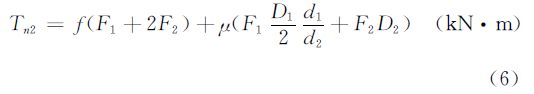
In the above formula:
The size is not yet accurate in the design phase, the value can take Di = 0.5di (i=1, 2). The lower roller drive torque T equals the sum of the deformation torque Tn1 and the friction torque Tn2.
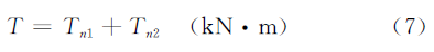
Lower roller driven power is:

In the above formula:
The power of the main motor can be obtained from the value of P.

As the founder of MachineMFG, I have dedicated over a decade of my career to the metalworking industry. My extensive experience has allowed me to become an expert in the fields of sheet metal fabrication, machining, mechanical engineering, and machine tools for metals. I am constantly thinking, reading, and writing about these subjects, constantly striving to stay at the forefront of my field. Let my knowledge and expertise be an asset to your business.