The fit between bearings, shafts, and bearing housings is a critical aspect in bearing applications, and is a topic of great interest to bearing users. In practical work, the standard selection principle for fit can satisfy application needs.
However, many engineers are curious about how this fit selection principle is calculated, and some even prefer to do the calculations themselves.
Indeed, the basic calculation method for selecting the fit between bearings, shafts, and bearing housings can be accomplished by recombining previous knowledge from the perspective of how the fit impacts bearing operation.
I. Boundary Conditions for Bearing, Shaft, and Bearing Housing Fit Calculation
Before performing the calculation for selecting the fit between bearings, shafts, and bearing housings, it’s crucial to understand the real purpose of this calculation, which provides a clear definition of the calculation method and boundary conditions.
Purpose of the Fit
The overall objective of the fit between the inner ring of the bearing and the shaft, and the outer ring of the bearing and the bearing housing, is to ensure that there is no relative movement between the bearing and the shaft, and between the bearing housing and the outer ring of the bearing.
Relative movement in both the circumferential and axial directions should be avoided. It’s important to understand that it’s challenging to prevent relative movement solely by the fit, so other external design elements must be used to ensure this.
For example, shaft shoulders and bearing housing steps are used to limit axial movement; designs using locking slots or O-rings to stop relative movement in the circumferential direction. These methods usually serve as a supplement when the fit alone cannot fulfill its function, preventing relative movement and ensuring a certain degree of reliability.
Fitting Boundaries
From the above discussion, we know there is a minimal boundary in the fitting of bearings and related components. If the fitting force is too small, it will cause relative movement between the bearing and the fitting surface, failing to serve its fixing role. This situation increases the probability of bearing displacement.
From the perspective of mechanical part design theory: the tighter the fit, the greater the fitting force, and consequently, the more significant the “fixing” effect. However, there is a degree of “loose” and “tight” fit.
If the fit is too tight, while it can ensure the relative fixation of the fitting surface, other dimensions within the bearing and the steel material of the bearing itself will be affected. Therefore, fixation cannot solely be achieved by increasing the fit.
On the other hand, in some applications, the “fitting force” generated between the two mutually fitting surfaces will vary (for example, in some vibration situations). Therefore, when the tendency for relative movement of the fitting surface occurs during the aforementioned force fluctuations, the required “fitting force” needs to be greater.
Why should it be larger? Because we need to ensure that during both the “strong” and “weak” stages of relative movement, this fitting force will not cause relative movement of the fitting surfaces. For instance, if we select the “fitting force” according to the “strong” stage of relative movement, when the vibration moves to the “weak” stage, this “fitting force” will seem too large.
Conversely, if we choose the “fitting force” according to the “weak” stage, then when it vibrates to the “strong” stage, we will find that this force is insufficient, and relative movement of the fitting surfaces has occurred. Thus, to cater to the peak, a larger fitting force is inevitably used.
This is why, in vibrating conditions, it is generally recommended to employ a tighter fit for the related bearing.
This is what we need to discuss: there is a maximum boundary for the fitting of bearings and related components. If the fitting force is too large, it will cause changes in other bearing properties, leading to problems.
In conclusion, the ultimate goal in selecting bearing tolerance fits is the fitting force between the bearing fitting surfaces. If this fitting force is too small, it may easily lead to relative movement (displacement) between the bearing and the fitting components; if the fitting force is too large, it can affect the internal performance of the bearing (too small clearance, increased preloading).
This is the basic boundary and calculation direction for the selection of bearing-shaft and bearing-housing tolerance fits.
II. Minimum fit force between the bearing, shaft, and bearing housing
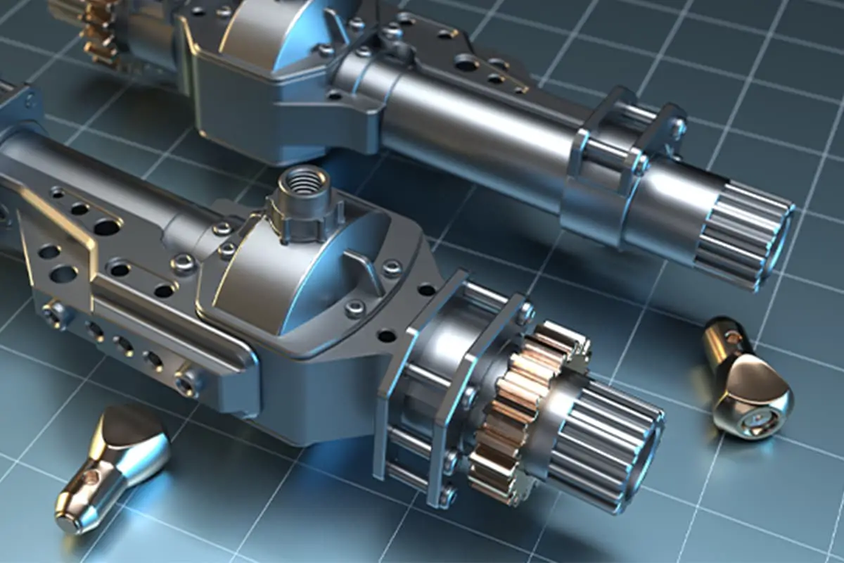
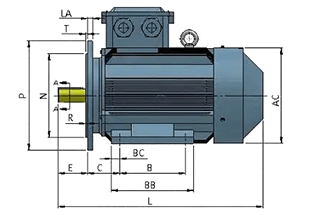
Example: General horizontal internal-rotation motor bearing.
The shaft system of a common horizontal internal-rotation motor has the simplest bearing configuration. Other types of shaft systems can be inferred based on this model.
When a horizontal internal-rotation motor is running, the motor’s rotary shaft will rotate with the inner ring of the bearing. Thus, the “rotation” is transmitted from the motor’s rotor to the bearing’s inner ring, implying that the inner ring of the bearing passively rotates. This being the case, a significant amount of driving force is required.
This driving force encompasses the force needed for the inner ring of the bearing, along with the rolling element and the cage, to rotate. Therefore, the most demanding operating condition for driving the inner ring of the bearing to rotate is during startup or speed changes. At this point, the minimum driving force is the centrifugal acceleration multiplied by the mass of the bearing’s inner ring.
The situation is slightly different when the bearing rotates at a uniform speed.
When a bearing moves at a constant speed, the drive force required is minimal, mainly to overcome the friction between the internal rolling elements and the raceways. Therefore, the necessary “fitting force” is much simpler than the aforementioned scenario.
Looking at two different applications, motors that frequently change speed or start up require much more “fitting force” than those running at a constant speed. This explains why the previously recommended fit charts often require a tighter fit for variable speed or frequent startup situations.
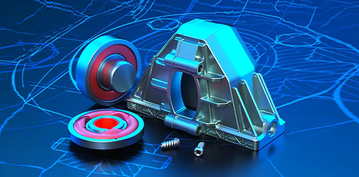
So far, we’ve been discussing the “rotating ring” – the inner ring. But what about the outer ring? In horizontal inner rotor motors, the outer ring of the bearing is typically stationary, and the bearing housing is also fixed.
The only force that tends to rotate the outer ring of the bearing is the rolling of the bearing rollers within the outer ring. Under normal circumstances, there is usually only rolling friction between the bearing rollers and the outer ring, so this fitting force only needs to exceed this rolling friction to overcome the tendency of the outer ring of the bearing to rotate.
Moreover, because the rolling friction is very small, the fitting force required by the bearing to overcome the rolling friction is also very small. However, there is a sliding friction between the bearing housing and the outer ring of the bearing.
At the same time, the radial load between the outer ring of the bearing and the bearing housing can be considered the same as the internal radial load of the bearing. Furthermore, there is a lubricant within the bearing raceway to reduce friction, while there is no lubricant between the outer ring of the bearing and the bearing housing.
In conclusion, by securely positioning the outer race of the bearing within the bearing housing, the tendency for relative motion can be overcome through sliding friction. It is thus easy to understand why the outer race of the bearing in a horizontal internally rotating motor is generally loosely fitted.
Returning to the main topic, it is quite straightforward to calculate the frictional force exerted on the outer race of a bearing by rolling bodies. Of course, my personal engineering experience suggests that such calculations are generally not necessary in practice, as standard fit selection tables typically suffice. Engineers with a curiosity to learn, however, may want to give it a try.
Here are some additional questions for engineers to consider (the thought process has been outlined above, just follow it):
1. Why does the fit need to be tight under vibration conditions, and does the outer race need to be tight?
2. How should the tolerance fit for a vertical motor be selected?
3. How should the tolerance fit for an externally rotating motor be selected?
The above content did not provide answers to the above questions. Everyone is encouraged to think about it on their own, and I believe everyone can derive the answers. (A small hint: consider elasticity.)
Under uniform motion, would the aforementioned outer race fitting result in orbiting?
III. The maximum interference fit between the bearing, shaft, and bearing housing.
We mentioned the boundary of the maximum interference fit. If the interference is too large, it can cause changes in other bearing performances.
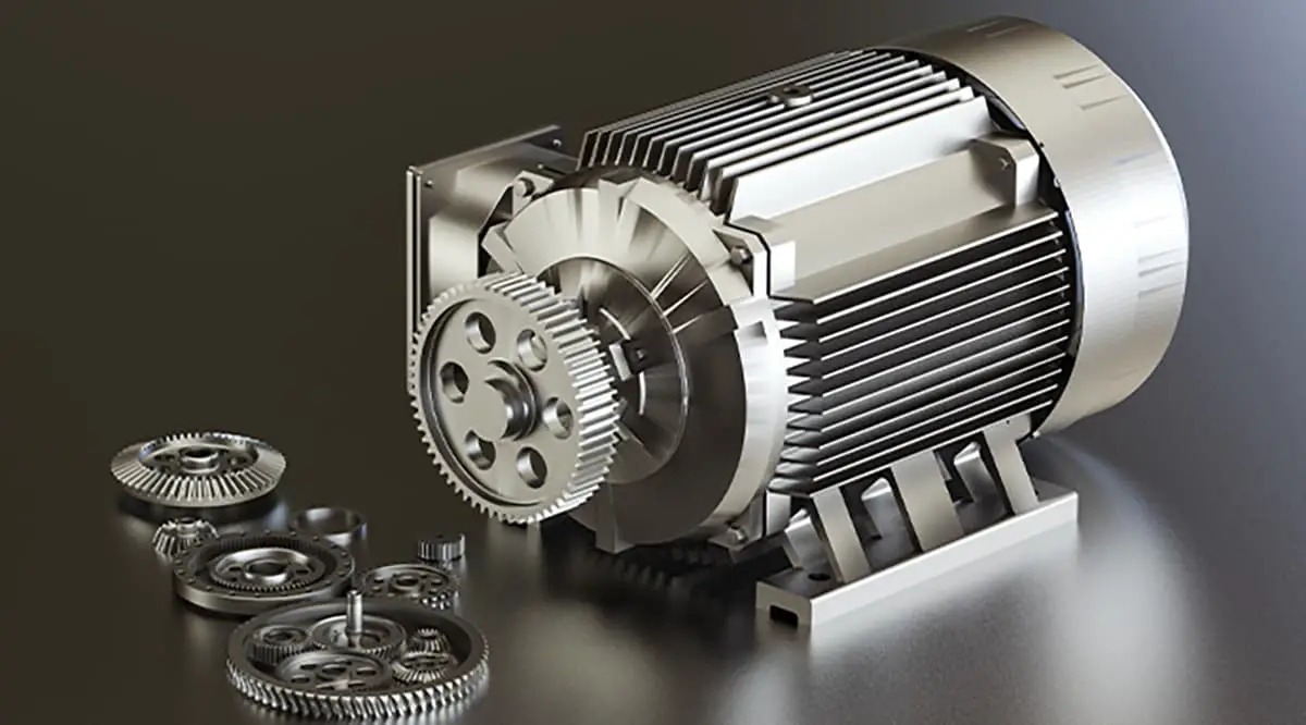
Firstly, the most important factor is the change in the bearing’s own dimensions. When the bearing is tightly fitted, the internal clearance of the bearing will decrease. When the bearing clearance is too small, the bearing can seize up. Therefore, the first requirement for the tightest bearing fit is to satisfy the requirement for residual bearing clearance.
These methods are commonly used in certain fields, such as in the application of gearbox bearings.
Secondly, the factors affected by the tight fit are the bearing materials, such as the cracking of the inner ring. This situation has indeed occurred in practical applications. However, generally, the impact of the bearing material occurs after the clearance effect.
II. Conclusion
These article primarily discuss the basic methods of calculating bearing and related component fits.
However, it’s crucial to understand that for motor bearing systems, such complex calculations are typically unnecessary. This is because daily recommended tolerance fit tables have already considered the aforementioned factors. Direct selection based on these principles is usually sufficient. We write this content to inform you how these reference results we use daily are derived.
Unless it’s a very specific application, or you are particularly enthusiastic about understanding the theoretical process, we do not recommend that each selection of fits undergo such complex consideration.
Of course, for gearbox engineers, particularly when calculating the preload of tapered roller bearings and angular contact ball bearings, such considerations become unavoidable and require careful understanding.