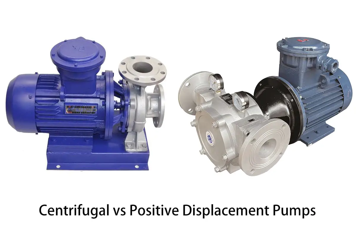
Centrifugal vs Positive Displacement Pumps: How to Choose?
Choosing the right pump can be daunting, especially when faced with the choice between centrifugal and positive displacement pumps. These two types of pumps serve different functions and have unique operational characteristics. This article will guide you through the essential factors to consider, including the properties of the liquid being pumped and the specific requirements of your system. By the end, you’ll understand the key differences and be equipped to make an informed decision that optimizes both efficiency and cost-effectiveness in your industrial applications.
Pumps are the second most commonly used industrial equipment after motors. Currently, millions of pumps are operating worldwide, conveying thousands of different types of liquids.
Selecting the right pump from the myriad of available options is a complex task. To a large extent, pump selection involves matching the capabilities of a specific pump to the system requirements and the characteristics of the fluid being pumped.
In this article, we’ll start with the properties of the pumped liquid, from the perspective of user requirements, and then delve into the specifics of pump selection.
1. Basic Requirements
In any application, the first step is to understand the basic requirements the user has for the pump. For example: inlet conditions, required flow rate, pressure differential, temperature, and fluid characteristics such as viscosity, abrasiveness, shear sensitivity, and corrosiveness. These conditions must all be determined before a pump can be selected.
Pumps need to operate under correct suction conditions to function well. In fact, the biggest problem encountered by pumps can be traced back to poor suction conditions. Since the pump’s ability to push liquid far exceeds its ability to draw liquid in, the inlet conditions should be kept within the pump’s capacity.
Pressure differential is also a critical factor, especially when considering energy conservation and pump lifespan. Using smaller pipe diameters and longer pipe lengths can reduce initial system costs, but may also result in a higher pressure differential for the pump.
This higher pressure differential can translate into energy consumption and potentially shorten the pump’s lifespan, which means higher operating costs and lower efficiency.
The required fluid characteristics are usually known, and the key is to understand how a given pump affects these characteristics. Most users prefer the liquid discharged by the pump to be in the same condition as when it entered the pump. For proper pump selection, the compatibility of materials, viscosity, shear sensitivity, and the presence of specific substances or solids are of utmost importance.
2. Centrifugal Pumps vs Positive Displacement Pumps
Once the basic requirements are met, and the characteristics of the liquid are known, the selection of the pump can begin. Pumps are generally divided into two basic categories: kinetic pumps (the largest type of which are centrifugal pumps) and positive displacement (PD) pumps.
According to data from the U.S. Department of Commerce, about 70% of all pump sales are kinetic pumps, while the remaining 30% are positive displacement pumps. The first step in choosing a pump is to determine which of the centrifugal pumps or positive displacement pumps is more suitable for your needs.
As the majority of industrial pumps are centrifugal, many people will first consider centrifugal pumps. The cost of centrifugal pumps is usually lower than that of positive displacement pumps, and they are also the correct type of pump to use in many situations.
Each type of pump stirs the fluid in its own unique way, and each has its own operational characteristics and curves. Importantly, centrifugal pumps affect the flow rate of the liquid, resulting in a certain pressure at the discharge port.
In contrast, a positive displacement pump stirs the liquid by first obtaining a specific amount of liquid and delivering it from the suction port to the discharge port.
For centrifugal pumps, pressure is formed first, followed by the generation of flow. For positive displacement pumps, flow is formed first, followed by the appearance of pressure.
Performance
In order to choose the most suitable type from various pumps, it’s crucial to understand the differences in the working characteristics of these two types of pumps. When looking at their performance charts (Figure 1a), you can see how different their working principles are.
Centrifugal pumps exhibit a variable flow phenomenon that depends on pressure (or head), while positive displacement pumps exhibit a more or less constant flow phenomenon that is independent of pressure.
Figures 1a-1d: The comparison between these charts shows some important differences between centrifugal pumps and volumetric pumps.
Viscosity
Viscosity plays a significant role in the mechanical efficiency of a pump. As centrifugal pumps operate at motor speeds, their efficiency declines with an increase in viscosity caused by greater frictional losses within the pump. Note that the rate of efficiency decrease in centrifugal pumps is rapid with increasing viscosity (Figure 1b).
Another major distinction is the effect of viscosity on pump capacity. In the flow rate chart (Figure 1c), you will notice a decrease in flow rate as viscosity increases for centrifugal pumps, whereas positive displacement pumps experience an increase in flow rate.
This is due to the higher viscosity liquid filling the voids within the positive displacement pump, resulting in higher volumetric efficiency. Figure 1c only represents the impact of viscosity on pump flow rate.
Bear in mind that there will also be an increase in pipeline loss within the system. This means that the flow within the centrifugal pump will further decrease with an increase in pump differential pressure.
Efficiency
When considering the effect of differential pressure on pump mechanical efficiency, kinetic and positive displacement pumps exhibit different characteristics. Figure 1d illustrates how pump efficiency is affected by increasing pressure.
For positive displacement pumps, efficiency actually improves with increasing pressure, whereas centrifugal pumps have a Best Efficiency Point (BEP). On either side of this point, the overall pump efficiency drops significantly.
Inlet conditions
These two types of pumps have significantly different requirements for inlet conditions. Centrifugal pumps need a certain amount of liquid in the pump to create a pressure differential. A dry pump without liquid cannot start on its own.
Once started, centrifugal pumps need to meet specific inlet pressure requirements recommended by the manufacturer.
Since positive displacement pumps stir liquid by expanding and contracting its volume, negative pressure is created at the inlet, allowing the pump to self-prime.
In some cases, this is the sole determining factor in choosing between a positive displacement or centrifugal pump.
Conclusion
In summary, when the viscosity exceeds 150 cP, and it’s necessary to predict flow rates over a wide range, or when self-priming is desired, a positive displacement pump can be considered. Energy consumption should also be taken into account when choosing between centrifugal and positive displacement pumps, as there may be significant differences in energy use between the two.
This is especially important for flow rates below 100 gallons per minute, where the decrease in efficiency is more pronounced for centrifugal pumps.
3. Volumetric Pump
Even after deciding to use a volumetric pump, there are still many options to consider. Before detailing the specifics of each pumping operation, let’s first review some common operational characteristics of volumetric pumps.
As mentioned above, a rotary volumetric pump discharges the same volume of fluid with each rotation of the shaft. This means that the flow rate of the discharged fluid is proportional to the speed of rotation.
In other words, the flow rate can simply be controlled by changing the speed of the pump. For more viscous fluids, the pump can be metered just by measuring the number of shaft rotations.
The structure of a volumetric pump requires tightly fitting internal components and a certain operating clearance. Because of this clearance, some fluid will flow back from the discharge end to the suction end.
This phenomenon is known as “slippage”. The amount of fluid that slips depends on the viscosity of the fluid, the pressure difference, and the internal clearance of the pump. Lower viscosity usually results in more slippage, whereas thicker fluids will slip less.
Since a volumetric pump always tries to discharge the same amount of fluid, it is important to have necessary overpressure protection devices in the system. When a blockage occurs in the pump discharge, it usually results in a pressure rise, which only stops when: the load exceeds the motor’s limit; some components in the system break and release the pressure; or the pump fails. All these situations are unsafe. A volumetric pump needs a way to relieve pressure.
To achieve pressure relief, there are several methods to choose from. Using a pressure relief valve is the most common one, but a rupture disc in the discharge line can also be used.
Since the drive torque is directly related to the differential pressure inside the volumetric pump, a torque-limited coupling can also be used. The key is to remember that very high pressures can build up inside the volumetric pump, and this must be limited in the event of a discharge blockage or partial blockage.
Volumetric pumps can be divided into many types. The American Hydraulics Institute, an organization formed by pump manufacturers, has published various publications on pump types and standards. They categorize rotary volumetric pumps as: impeller, piston, cam, gear, ring piston, and screw.
In addition, there are subcategories for each type of pump, meaning there are many types of volumetric pumps. All these pumps have the same function of conveying fluid, so how do we choose the right one?
While most volumetric pumps can be modified to suit a wide range of applications, some types are better than others for a given environment. Fortunately, for basic fluid conveyance, a few pumps have proven to be superior. In the following sections, we will discuss the performance characteristics of internal gear pumps, external gear pumps, and impeller pumps.
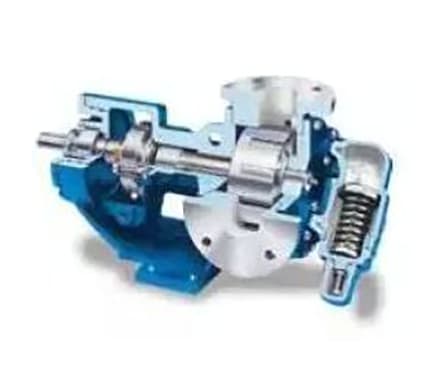
4. Internal Gear Pump
The internal gear pump comprises an external gear component known as the rotor, which is responsible for driving the internal gear, also known as the idler (Figure 2). The idler is slightly smaller than the rotor and rotates around a stationary pin while operating within the rotor.
When these components disengage, a certain gap space is formed, allowing the liquid to flow into the pump. As these components engage, the volume of space gradually decreases, forcing the liquid to flow out of the discharge port.
The liquid can flow into the expanding cavity through the gears of the rotor and the recess under the pump head. The final key element of this type of pump design is the crescent-shaped barrier, which is integrated with the pump head.
The crescent-shaped barrier seals the volume of liquid between the idler and the gear, serving as a seal between the intake and discharge ports.
Figure 2- The internal gear pump is ideal for high viscosity liquids, but it can cause damage when pumping high turbidity liquids.
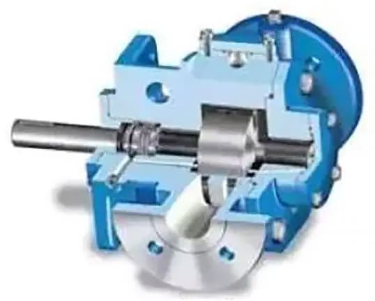
Fig. 3. The internal gear system is provided with high-adhesion shaft support by the shaft neck and wear-reducing bearings.
The rotor gear is secured on a gear shaft and supported by a shaft collar or anti-friction bearing (Figure 3). The idler gear assembly also includes a collar bearing that is located within the pumped liquid and rotates around a fixed pin.
Depending on the arrangement of the shaft seal, the rotor shaft support bearing can operate within the pumped liquid. This aspect needs to be emphasized when conveying corrosive liquids, as they can corrode the support bearing.
The actual pressure limit of such pumps depends on the operation of the rotor shaft support bearing. The differential pressure rating of the vast majority of internal gear pumps is 200 psi, although they can be used for higher pressures under the correct application conditions.
The speed of internal gear pumps is relatively slower compared to centrifugal pumps. Generally, the maximum is 1150 rpm, but some small design schemes can reach 3450 rpm. Because internal gear pumps can operate at low speeds, they are well suited for conveying high-viscosity fluids, though they can also be successfully applied to thin liquids. Internal gear pumps have successfully pumped liquids with viscosities over 1,000,000 cSt and very low-viscosity liquids, such as liquid propane and ammonia.
The flow range of this type of pump ranges from 0.5 gallons/minute to 1500 gallons/minute. Materials include cast iron and a variety of different corrosion-resistant alloys, including Hastelloy.
Internal gear pumps adopt a tight tolerance design during manufacturing, which can be damaged when pumping larger solids. This type of pump can convey small suspended particles in corrosive applications, but it will wear and gradually degrade performance.
In corrosive applications, by choosing corrosion-resistant materials, the pump’s lifespan can be greatly extended. In this case, tungsten carbide, hardened steel, or various coatings can all provide excellent results.
Internal gear pumps have a very broad range of applications and can even be effectively used for shear-sensitive liquids. Application areas include wastewater, polymers, shear-sensitive paints, asphalt emulsions, and certain foods, such as mayonnaise.
When using this type of pump, only a very small amount of liquid is subjected to shear forces at any time. Moreover, when necessary, the clearance and speed can be adjusted to minimize the impact of shear forces.
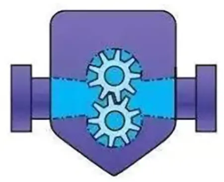
4. External Gear Pumps
External gear pumps operate similarly to internal gear pumps in pumping action, which is by engaging and disengaging two gears to drive the fluid flow (Figure 4).
However, external gear pumps use two completely identical gears that mesh and rotate with each other. Each gear is supported by a gear shaft, and there is a bearing on both sides of each gear. Typically, all four bearings operate within the pumped liquid.
Figure 4: The excellent bearing support capacity of the external gear pump is highly suitable for high-pressure application fields.
Figure 5: Customized external gear pumps like these twin-linked pumps can be applicable for multi-fracture segment applications.
As the gear is supported on both sides, the external gear pump can be used in high-pressure applications, such as within hydraulic devices.
Pumps designed for hydraulic supply can withstand pressures of thousands of pounds per square inch. Industrial conveyor pumps can withstand even higher pressures, but the characteristics of the liquid may limit the pressure range.
Thinner liquids can reach hundreds of psi, while more viscous liquids can approach the pressure of hydraulic pumps. Typically, smaller external gear pumps should operate within a range of 1750 to 3450 rpm, while larger external gear pumps operate at a maximum speed of 640 rpm.
The flow range of the external gear pump ranges from very low (a few drops per minute) to quite high at 1500 gallons per minute. External gear pumps can be manufactured from a variety of raw materials, including high-end alloys.
External gear pump designs can use tighter tolerances than internal gear pumps. However, external gear pumps do not tolerate particulate matter in the pumped liquid well. Since there is a gap at both ends of the gear, it is not possible to adjust the end gap for wear. After the external gear pump wears out, it must be reassembled or replaced.
As long as the speed is set correctly, especially for liquids with higher viscosity, the external gear pump can handle both viscous and aqueous liquids. Since viscous liquids need some time to fill the spaces between the gear teeth, the pump’s speed must be significantly reduced when pumping viscous liquids. Its viscosity limit is actually the same as that of an internal gear pump, both at 1,000,000 cSt.
The performance of the external gear pump under critical suction conditions is not ideal, especially for volatile liquids. Volatile liquids often undergo partial evaporation when the space between the teeth rapidly expands.
5. Impeller Pump
The working principle of the vane pump is theoretically similar to other volumetric pumps with expanding and contracting volumes, but it employs a different mechanism to realize this theory (Figure 6). Interestingly, the impeller pump is essentially two pumps in one.
The first pumping action is generated by the volume expansion between the impeller, rotor, and pump casing, while a less noticeable pumping action occurs within the area beneath the impeller.
In this area, whether the impeller enters or exits the rotor slot, a pumping action is formed, which actually accounts for about 15% of the total pump displacement.
Typically, this area is ventilated through the slots inside the impeller or the rotor. It’s crucial to understand this, especially when dealing with more viscous liquids, as the flow of viscous liquid into and out of the area between the impellers can be more challenging.
Therefore, the maximum medium viscosity recommended for this type of pump is approximately 25,000 cSt.
Figure 6: The dry start priming capability of the impeller pump is superior to other volumetric pumps.
Figure 7: Non-metallic impellers can be used in centrifugal pumps to achieve superior performance when pumping thin liquids.
The impeller, which is the main sealing component between the intake and discharge ports, is usually made of non-metallic composite materials. Because there is no metal-to-metal contact, impeller pumps are frequently used for low-viscosity liquids without lubricating effects, such as propane and ammonia. As the impeller directly contacts the pump casing and the internal clearance is minimized, the slip characteristics of thin liquids can be optimized.
Most conveyor impeller pumps limit the pressure to 125 psi, although some are rated for 200 psi. The pressure limit of the impeller pump largely depends on the strength of the impeller.
Thanks to the non-metallic impeller and very small operating clearances, impeller pumps can start priming operations very well. When the pump starts the priming operation, it must discharge air, and what is discharged is a very thin fluid. Because impeller pumps can do this well, they are sometimes used as vacuum pumps.
Impeller pumps are typically supported on both sides of the rotor by shaft sleeves or anti-friction bearings. If shaft sleeve bearings are used, they will operate in the liquid. If anti-friction bearings are used, the pump’s internal seals must be used to allow the bearings to operate in lubricating oil or grease. This design requires two mechanical seals, one on each side of the rotor.
Impeller pumps usually operate within the speed range of 1000 to 1750 rpm, and the flow rate can reach up to 2000 gallons/minute. However, when dealing with high viscosity liquids, the required speed will be significantly reduced to allow the liquid to enter under the impeller.
In applications dealing with high viscosity liquids, impellers made of stronger materials are required to prevent breakage. The most common materials for impeller pump construction are cast iron or ductile iron. Some manufacturers use stainless steel materials in pumps that must handle thin, corrosive liquids.
Impeller pumps can handle some corrosive substances, but not solids. For corrosive substance pumping applications, caution must be exercised in correctly choosing the impeller and seal materials. Like external gear pumps, impeller pumps have fixed end clearances at both ends of the rotor and impeller.
Once wear occurs, these clearances cannot be adjusted, however, some manufacturers now offer replaceable or reversible end covers. Using a casing liner is also a way to restore pump performance when wear occurs.
Summary
Understanding the working principles of various pumps is a good start to properly select a model for a given application environment. Although the distinctions between various options may not be very clear, basic differences in operation and capacity can be used to guide selection.
Internal gear pumps can be used in a wide range of applications, but they usually operate slower than other pumps. Initially, choosing an internal gear pump may incur slightly higher costs, but compared to slower-running pumps, its service life tends to be longer.
External gear pumps have excellent pressure handling capabilities and precise flow control characteristics, but they cannot be used to handle solid or corrosive media. The manufacturing cost of external gear pumps is lower, so they are an economical and reasonable choice in lower-demand application fields.
Impeller pumps perform well when conveying thin liquids, but must operate at reduced speeds when handling viscous liquids. Impeller pumps also cannot handle solid materials.
Incorrect pump selection often leads to higher costs. Specifically, it can negatively impact downtime, loss of production, maintenance costs, and energy consumption. Spending more time choosing the right pump in the right system can minimize unnecessary cost outlays and achieve higher long-term benefits.
As the founder of MachineMFG, I have dedicated over a decade of my career to the metalworking industry. My extensive experience has allowed me to become an expert in the fields of sheet metal fabrication, machining, mechanical engineering, and machine tools for metals. I am constantly thinking, reading, and writing about these subjects, constantly striving to stay at the forefront of my field. Let my knowledge and expertise be an asset to your business.
Have you ever wondered how industries achieve that perfect finish on metal parts? This blog explores the fascinating world of shot blasting and sand blasting. You'll learn how these processes…
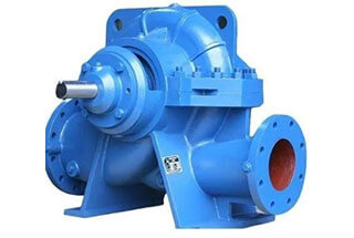
Have you ever wondered what makes certain pumps more efficient for different applications? In this article, we’ll explore the fascinating differences between double suction and single suction pumps. You’ll learn…
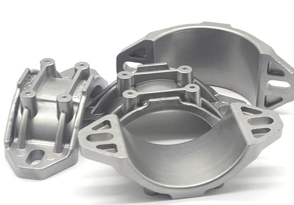
Have you ever wondered about the fascinating world of casting? This ancient yet ever-evolving manufacturing process shapes our daily lives in countless ways. In this blog post, we'll explore the…
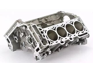
Have you ever wondered what makes your car's engine parts so durable and efficient? This article unveils the secrets behind casting aluminum alloys, the unsung champions of automotive engineering. Learn…
Have you ever wondered what goes into choosing the perfect water pump? In this blog post, we'll dive into the world of pump manufacturers and explore the key factors to…
Have you ever wondered how the intricate parts of your car are made? This article reveals the fascinating world of automotive casting, detailing the advanced technologies and methods that shape…
This article dives into the fascinating world of casting production, revealing the step-by-step process that turns raw materials into essential components. Learn about the techniques, materials, and quality checks involved,…
Ever wondered how the gleaming finish on stainless steel is achieved? This article dives into the meticulous process of mechanical polishing, explaining techniques, tools, and best practices. From rough polishing…
Ever wondered what keeps your car engine running smoothly? The answer lies in lubricating oils. These complex mixtures of hydrocarbons perform critical roles, from reducing friction to preventing rust. This…