The Ultimate Guide to Encoders: Types, Applications, and Benefits
Have you ever wondered how machines precisely know their position and speed? This article explores the fascinating world of encoders, sensors crucial for detecting mechanical motion. You’ll learn about different types of encoders, their working principles, and their applications in modern machinery. Get ready to uncover the secrets behind the precision of motor controls and more!
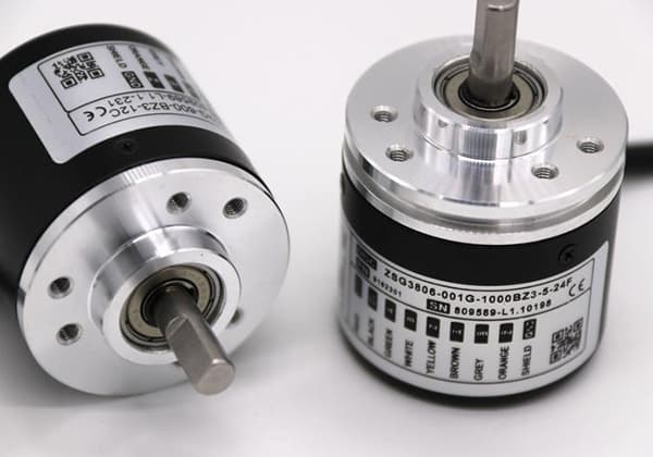
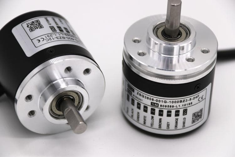
Encoders are a type of sensor used primarily to detect the speed, position, angle, distance, or count of mechanical motion.
In addition to being used in machinery, many motor controls such as servo motors require encoders to provide feedback for commutation, speed, and position detection to the motor controller.
2. Classification of Encoders
The encoder can be divided into analog encoder and digital encoder. Analog encoder can be further divided into rotary transformer and Sin/Cos encoder, while digital encoder can be divided into incremental encoder and absolute encoder.
3. Working Principles of Commonly Used Encoders
3.1 Principle of digital encoders
1)Use photoelectric couplers to scan a segmented disc installed on a mechanical shaft.
The mechanical code is converted into proportional electrical pulse signals.
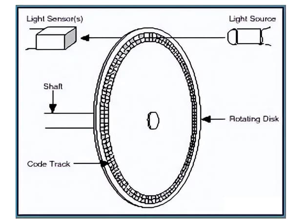
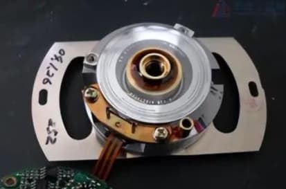
The light source (generally an LED) emits a narrow beam of light towards the receiver (which may be a photodiode). Both the light source and the receiver are strictly installed in stationary parts of the rotating connecting bearing.
The encoder is a shading disk with a transparent opening or window, which is installed in the rotating part of the bearing.
3.2 Principle of photoelectric digital encoders
When the bearing rotates, the encoder allows the light beam to alternate through (pass through the small window on the disk).
The photodiode outputs corresponding high or low-level signals as the position changes. The output of the photodiode can be converted into position and velocity information through a specialized circuit.
3.2.1 Output of Incremental Encoders
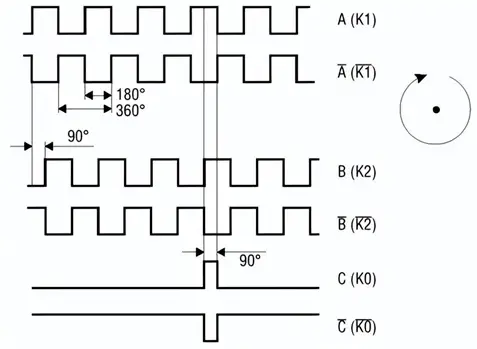
The incremental encoder output consists of a center-shafted photoelectric disk with circular transparent and opaque markings, which are read by photoelectric emitter and receiver components to obtain square wave signals combined as A, B, -A, -B.
Each pair of signals has a 90-degree phase difference C (one cycle equals 360 degrees).
In addition, there is a zero-point calibration signal, and the encoder outputs one signal per rotation of the disk.
Output schematic diagram of incremental encoder
3.2.2 Connection principles of incremental encoders
1. Single-phase connection
Used for single-directional counting and uni-directional speed measurement.
2. A-B two-phase connection
Used for bi-directional counting and determining direction and speed.
3. A-B-C three-phase connection
Used for determining speed with reference position correction.
A-A-B-B-C-C connection has symmetric negative signal connection current, which has minimal attenuation and strong anti-interference, and can be output over long distances.
How to determine direction
Since A and B are 90 degrees out of phase, direction can be determined by detecting whether A or B occurs first.
How to perform zero-position calibration
During the transmission of encoder pulses, errors may occur due to reasons such as interference, resulting in transmission errors.
At this time, it is necessary to perform timely zero-position calibration.
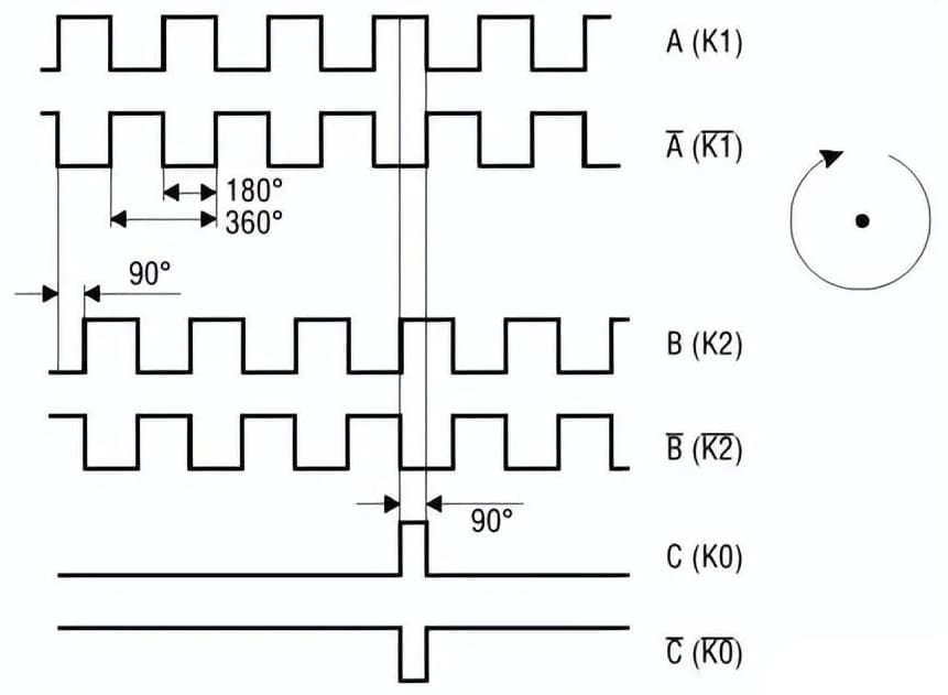
The C encoder outputs one pulse every rotation, which is called a zero pulse or an identification pulse, and is used to determine the zero or identification position.
To accurately measure the zero pulse, regardless of the rotation direction, the zero pulse is output as a high-level combination of two channels.
Due to the phase difference between the channels, the zero pulse is only half the length of the pulse.
Schematic diagram of zero point correction
3.2.3 Multiplier of Incremental Encoders
Due to technological and sampling limitations, it is impossible to achieve finer and more precise physical division of the encoding disk.
However, higher pulses can be achieved through digital circuit conversion.
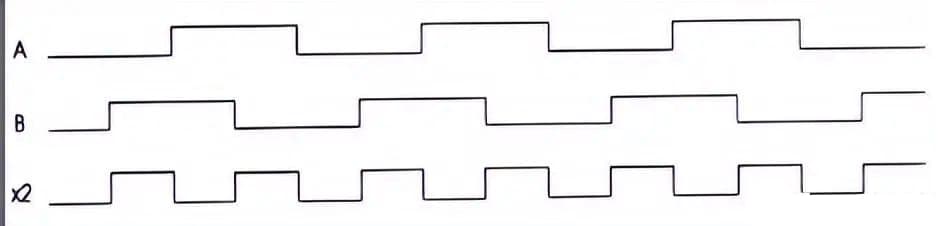
Double-frequency signal
Obtained by “exclusive or” conversion of A and B phases.
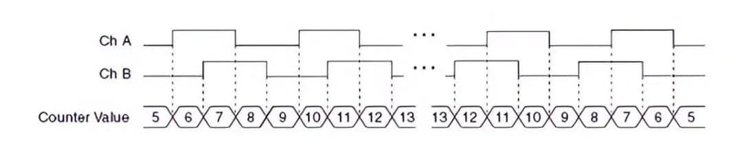
Quadruple-frequency signal
The counter also increases or decreases on each edge of channels A and B. The direction of the counter is determined by which channel leads the other.
The number in the counter increases or decreases by 4 each cycle.
3.2.4 Features of Incremental Encoders
The encoder outputs a pulse signal for each pre-set angle of rotation, and the rotation angle is calculated by counting the number of pulse signals.
Therefore, the position data output by the encoder is relative.
Since a fixed pulse signal is used, the starting position of the rotation angle can be arbitrarily set.
Due to the use of relative encoding, the rotation angle data will be lost and need to be reset after a power outage.
3.2.5 Problems with Incremental Encoders
1) Incremental encoders have zero-point cumulative errors.
2) They have poor anti-interference capability.
3) The receiving device needs to be powered off and the reference position found again after power outages or shutdowns.
The emergence of absolute encoders solves these problems.
3.3 Absolute Encoder Principle
An absolute encoder has a light code disc with several light channels and lines engraved onto it.
Each channel is coded using 2, 4, 8, 16, and so on lines in sequence.
At every position of the encoder, the light channels are read and their on/off state is used to obtain a unique binary code, known as Gray code, ranging from 2^0 to 2^(n-1), where n is the number of bits of the absolute encoder.
The position of the encoder is determined mechanically by the light code disc, so it is not affected by power outage or interference.
3.3.1 Absolute Encoder Code Disc
The light code disc is scanned by a group of photoelectric couplers to obtain the unique code at each position. Each position has its own unique code.
The output codes of absolute encoders are:
1. Natural binary code: 0000 0001 0010 0011 0100
2. Gray code: 0000 0001 0011 0010 0110
Gray code characteristics:
Adjacent integers in its numerical representation have only one difference, which can avoid the occurrence of large peak current in the digital conversion circuit (such as 3-4, 0011-0100).
Binary-Gray code conversion format:
The higher digits are retained, and the second highest digit is obtained by performing an “exclusive or” operation on the higher digits and the second highest digit (in binary).
Reference for decimal and Gray codes.
Decimal
Gray Code
0
0000
1
0001
2
0011
3
0010
4
0110
5
0111
6
0101
7
0100
Decimal
Gray Code
8
1100
9
1101
10
1111
11
1110
12
1010
13
1011
14
1001
15
1000
3.3.2 Output Formats of Absolute Encoders
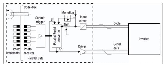
1. Parallel Output Mode
In this mode, there is one cable for each bit of data (bit channel), and the signal level (high or low) on each cable represents a 1 or a 0.
The physical device is similar to an incremental encoder and has different types such as collector open PNP, NPN, differential drive, push-pull, and differential high or low effective based on the physical device format.
The parallel output is generally in the form of a Gray code, also called a Gray code encoder.
2. Synchronous Serial Interface (SSI) Output
In this mode, data is concentrated and transmitted through a group of cables. The data output is ordered by a communication protocol that specifies the timing.
Serial output uses fewer connection lines and can transmit over longer distances, which greatly improves the protection and reliability of the encoder.
High-bit absolute encoders and multi-turn absolute encoders usually use serial output.
3. Asynchronous Serial Format
In this mode, instructions and data are exchanged through question and answer, and the interface is duplex. A typical example is the RS485 interface, which only requires two cables.
The data content can be the encoder’s position value or other content requested by the instruction.
For example, if an address is added for each encoder, multiple encoders can share the transmission cable and subsequent reception. This form is called a fieldbus type.
4. Principle of Hybrid Encoder
The incremental encoding and absolute encoding are both integrated on the same disk.
The outermost circle of the disk contains high-density incremental stripes, while the middle part is the binary Gray code channel of the absolute encoder.
The rotation of the disk is indicated by counting the number of pulses per rotation, and the angle turned within a week is counted using the numerical value of the Gray code.
Multi-turn absolute encoder: based on the single-turn absolute encoder, the principle of clock gear mechanism is used to transmit the rotation of the central disk to another set of disks (or multiple sets of gears and disks) through gear transmission, which adds the coding of the number of turns on the basis of single-turn coding to expand the measurement range of the encoder.
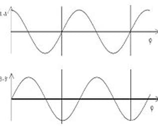
When parallel light passes through a grating, the intensity of the Moiré fringes produced approximates a cosine function.
By placing four 1/4 Moiré fringes of photosensitive elements in the direction of Moiré fringe movement, four sets of sine and cosine output signals can be obtained.
Output form of Sine-Cosine Encoder
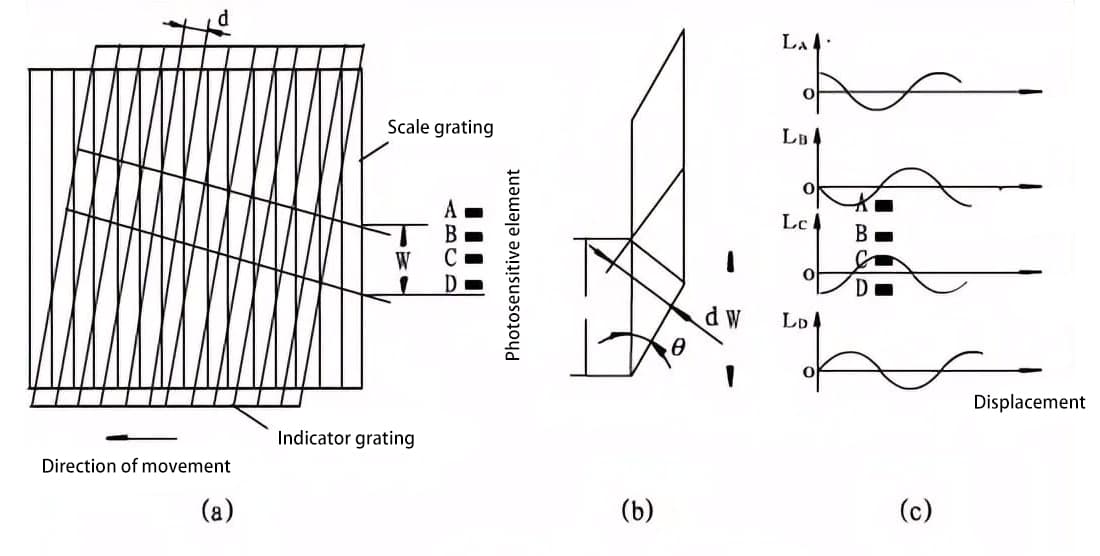
Figure Working principle of grating
Linear Encoder
A linear encoder measures the linear travel distance of an object and converts the measured distance into a pulse electrical signal output.
In simple terms, the principle is to stretch the disk of a rotary encoder into a straight line.
Grating Scale Encoder
The working principle of the grating displacement sensor is that when the master grating (i.e. the scale grating) and the auxiliary grating (i.e. the indicator grating) in the grating pair are relatively displaced, the interference and diffraction of light produce a regular black-and-white (or bright-dark) striped pattern, called Moiré fringe.
The black-and-white (or bright-dark) stripes that are the same are converted into sine wave-changing electrical signals through photoelectric devices.
After amplification and shaping by shaping circuits, two sine wave or square wave signals with a phase difference of 90 degrees are obtained and sent to the grating digital display for counting and display.
Rotary Transformer
A rotary transformer, also known as a resolver, is a type of micro-motor used for control purposes.
It is an indirect measurement device that converts mechanical rotation into an electrical signal that is related to the rotation angle by a certain mathematical function.
Principle of Rotary Transformer
1. A rotary transformer is a signal component that outputs a voltage that varies with the rotor angle.
When the excitation winding is excited by an alternating voltage of a certain frequency, the voltage amplitude of the output winding is in a sine or cosine function relationship with the rotor angle, or maintains a certain proportional relationship, or has a linear relationship with the rotor angle within a certain range.
2. The magnetic flux distribution between the stator and rotor of the rotary transformer follows a sine rule.
Therefore, when the excitation voltage is applied to the stator winding, the rotor winding generates an induced electromotive force through electromagnetic coupling, as shown in the above figure.
The magnitude of the output voltage depends on the angular position of the rotor, and thus varies sinusoidally with the displacement of the rotor.
According to the transformer principle, assuming the number of turns in the primary winding is N1 and the number of turns in the secondary winding is N2, k = N1 / N2 is the turns ratio. When an AC voltage is applied to the primary winding
Application of Rotary Transformer
1. Phase Detection Mode
The phase angle of the induced voltage is equal to the mechanical rotation angle of the rotor.
Therefore, as long as the phase angle of the output voltage of the rotor is detected, the rotor rotation angle is known.
2. Amplitude Detection Mode
In practical applications, by continuously modifying the electrical angle of the modulation voltage, the variation of the mechanical angle can be tracked, and the amplitude of the induced voltage can be measured to obtain the mechanical angle displacement.
5. Installation Precautions for Encoders
Mechanical Aspects:
1. Pay attention to the allowable shaft load during installation;
2. Ensure that the difference in axis of the encoder shaft and the user output shaft is less than 0.20mm, and the deviation angle from the axis is less than 1.5°;
3. During installation, avoid hitting, dropping, and colliding to prevent damage to the shaft and disk;
4. During long-term use, regularly check whether the screws fixing the encoder are loose (once per quarter).
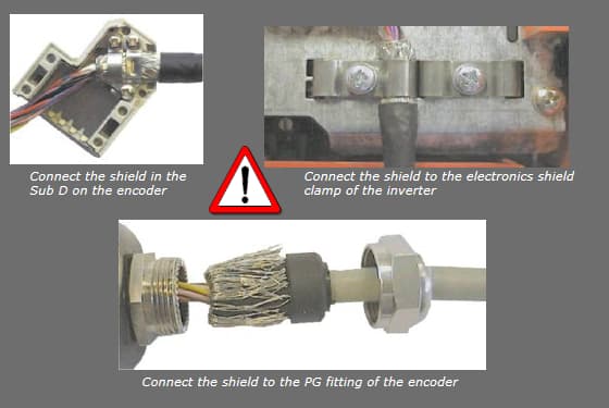
Electrical Aspects:
1)The grounding wire should be as thick as possible, generally greater than 1.5 square millimeters;
2)The output wires of the encoder should not overlap with each other to avoid damage to the output circuit;
3)The signal wires of the encoder should not be connected to DC power or AC current to avoid damage to the output circuit;
4)The equipment, such as motors, connected to the encoder should be well grounded and free from static electricity.
As the founder of MachineMFG, I have dedicated over a decade of my career to the metalworking industry. My extensive experience has allowed me to become an expert in the fields of sheet metal fabrication, machining, mechanical engineering, and machine tools for metals. I am constantly thinking, reading, and writing about these subjects, constantly striving to stay at the forefront of my field. Let my knowledge and expertise be an asset to your business.
Attention all mechanical engineers and manufacturing professionals! Are you struggling with pesky anodizing defects in your aluminum products? Look no further! In this blog post, we'll dive deep into the…
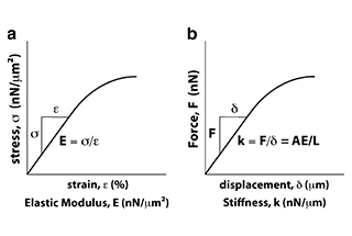
Ever wondered why some materials bend easily while others remain rigid? This blog dives into the fascinating world of elastic modulus and stiffness, unraveling their crucial roles in engineering. By…
Have you ever wondered what makes a perfect circle? In the world of mechanical engineering, roundness is a crucial concept that affects the performance and longevity of rotating components. This…
In today's fast-paced manufacturing world, efficient deburring is crucial. With numerous methods available, choosing the right one can be daunting. In this blog post, we'll explore various deburring techniques, from…
Have you ever wondered what keeps the world spinning smoothly? The unsung heroes behind the scenes are bearings. These small but mighty components play a crucial role in reducing friction…
Gears are the unsung heroes of the mechanical world, quietly working behind the scenes to keep machines running smoothly. But have you ever wondered what materials these critical components are…
This article explores the top 5 cooling tower manufacturers shaping our world. Learn how these companies innovate to keep industries running smoothly and efficiently. Get ready to uncover the secrets…
Have you ever wondered what keeps our gas systems running smoothly and safely? In this article, we explore top gas regulator manufacturers, uncovering their innovations and contributions to the industry.…
Ever wondered why connecting copper and aluminum wires is problematic? This article explains the risks associated with connecting these two metals due to their differing electrochemical properties, which can lead…