304 & 316 Stainless Steel Plate Weight Chart
Have you ever wondered about the weight differences between 304 and 316 stainless steel plates? In this blog post, we'll dive into the fascinating world of stainless steel, exploring the…
Have you ever wondered why steel sometimes fails unexpectedly? In this illuminating blog post, we’ll dive deep into the fascinating world of steel defects. As an experienced mechanical engineer, I’ll shed light on the various types of flaws that can compromise steel’s strength and performance. Discover the hidden causes behind these imperfections and learn how to identify and prevent them. Get ready to gain invaluable insights that will change the way you view steel forever!
Steel defects refer to various abnormal occurrences on the surface or inside of steel during its production or use that may impact its performance and quality.
Common surface defects in steel include cracks, scratches, folds, ears, scabs (heavy skin), welding scars, and end burrs. Additionally, there are typical surface defects like rolling oxides, patches, splits, pitted surfaces, and inclusions.
The causes of steel defects are diverse, such as severe damage or wear of the previous hole type roll groove, foreign metals falling on the rolled pieces and being pressed into the steel surface, or defects on the surface of the previous pass rolled piece. The oxidative atmosphere during heating also leads to steel oxidation, forming oxides such as FeO, Fe2O3, Fe3O4 on the workpiece surface.
Steel defect detection techniques mainly divide into traditional manual visual detection and automated detection based on computer vision. In recent years, methods based on deep learning, like YOLOv5 and YOLOv7, have been extensively applied in the automated detection of steel surface defects.
For certain specific defects, like banding, they can be eliminated through the method of high-temperature diffusion annealing. This process involves heating above 1050℃ to allow for uniform carbon atom diffusion, thereby eliminating banding.
Steel defects not only affect the physical properties of steel but may also present safety hazards during use. Therefore, the detection and treatment of steel defects are crucial to ensure steel quality and safe usage.
The specific reasons and mechanisms for the defects in steel mainly include the following points:
Surface defects: These defects include cracks, scratches, folds, ears, etc. The formation of cracks may be due to subsurface bubbles in the steel ingot, uncleaned cracks, and non-metallic inclusions that rupture or extend during rolling, as well as internal cracks in the steel ingot that expand and expose to the surface during rolling. In addition, factors such as inconsistent cooling conditions on both sides of the steel plate, uneven temperature of the rolled piece, uneven deformation during the rolling process, and uneven spray water cooling on the steel belt roller path can also cause surface defects.
Internal defects: These include shrinkage residuals, delamination, white spots, segregation, non-metallic inclusions, looseness, etc. These defects are mainly caused by equipment, process, and operation reasons during the steelmaking process.
Shape and size defects: These defects may involve size control issues during the production of steel. Although the specific generation mechanism is not detailed in the information I searched for, it can be inferred that it is related to temperature control, pressure distribution, and other factors during the production process.
Other factors: For example, deficiencies caused by equipment, process, and operation reasons during the smelting and rolling (forging) processing of carbon steel, including scabs, non-metallic inclusions, etc. In addition, the impact of irresistible factors such as material properties and processing technology in steel production may also cause different types of defects on the surface, such as rolling scales, spots, etc.
Materials form the foundation for the production of durable tools. During actual production, various types of material defects are frequently encountered.
Today, we will enlighten you on the 16 types of steel defects so that you are cautious when selecting raw materials.
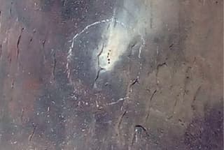
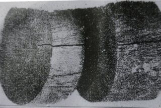
After conducting an acid etching test on steel, it was discovered that some regions of the sample’s surface were not dense and displayed visible voids.
These voids, which appear as dark spots with uneven color shades compared to other areas, are known as porosity.
When the porosity is concentrated in the central part of the sample, it is referred to as central porosity, whereas if it is evenly distributed on the surface, it is called general porosity.
Both GB/T9943-2008 for High-Speed Tool Steel and GB/T1299-2014 for Tool Steel have specific regulations regarding the porosity of steel, but supplies often exceed the standard.
Porosity has a significant impact on steel strength, and its main hazards are as follows:
Since porosity affects the performance of steel, tool steel has stringent requirements for allowable porosity levels.
Figures 1 and 2 depict φ90mm W18Cr4V (abbreviated as W18) steel raw materials, showing porosity and porosity cracking patterns after a heat etching treatment with 1:1 HCl.
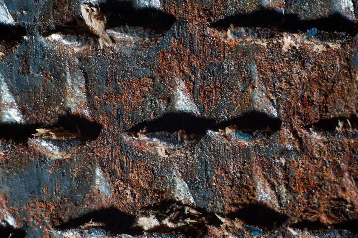
Figure 3 shows a picture of a W18Cr4V steel slotted milling cutter that suffered severe cracking due to sparing during heat treatment, as depicted through heat etching with 1:1HCl.
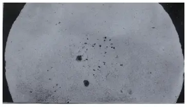
Figure 1 Central porosity
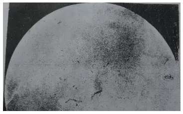
Figure 2 Cracks of central porosity steel during forging billets
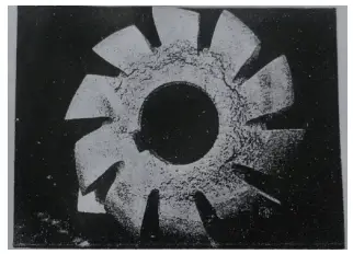
Figure 3 Cracks of slotting cutter material due to porosity during heat treatment
During the casting of an ingot, the liquid steel condenses and shrinks in the central part, forming a tubular hole known as shrinkage.
Typically, shrinkage is found near the feeder in the head of the ingot and should be removed when forming the billet.
However, the portion that cannot be completely removed is referred to as shrinkage residue.
While it is ideal to completely remove shrinkage, steel mills often prioritize production efficiency and leave a residue, resulting in irreversible consequences for subsequent processes.
Figure 4 shows φ70mm W18 steel with shrinkage residue and severe porosity, as depicted through heat etching with 1:1 HCl.
Figure 5 displays φ70mm W18 steel with shrinkage residue that has formed cracks after rolling, as depicted through heat etching with 1:1 HCl.
A few years ago, a company encountered shrinkage residue while sawing φ75mm M2 steel.
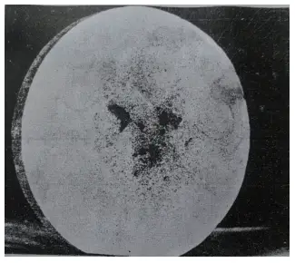
Figure 4
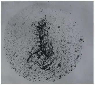
Figure 5: Cracks caused by W18 steel shrinkage
Longitudinal cracks on the surface of high-speed steel raw materials are a common occurrence.
There can be various causes for this, such as:
(1) During hot rolling, stress concentration may occur during the cooling process, leading to cracks along scratch lines due to incomplete removal of surface cracks or scratches caused by die holes.
(2) Poor die holes or large feed rates during hot rolling can lead to folds, which cause cracks along fold lines in subsequent processing.
(3) Cracks can be produced during hot rolling if the rolling stop temperature is too low or the cooling rate is too fast.
(4) Surface cracks are frequently observed on 13mm × 4.5mm W18 steel flat steel that is rolled in cold winter weather, indicating that the cracks may also be influenced by climatic conditions.
However, no cracks are observed when the same steel grade and specification is rolled at other times.
Figure 6 shows the surface crack of φ30mm W18 steel, with a depth of 6mm, as depicted through heat etching with 1:1 HCl.
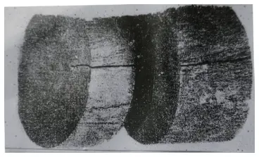
Figure 6 Surface crack
During the hot rolling process of high-speed steel, excessive deformation can cause the central temperature to increase rather than decrease. This can lead to the formation of cracks in the material center due to thermal stress.
Figure 7 shows the center crack in φ35mm W18 steel (etched with 1:1 HCl).
Central cracks in high-speed steel raw materials are common in tool plants, however, they are harmful as they are invisible and cannot be detected by touch. The only way to observe these cracks is through flaw detection.
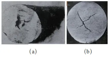
Figure 7 Central crack
The uneven distribution of chemical elements within an alloy during the solidification process is known as segregation. This can have a significant impact on the performance of the steel, especially if there is an uneven distribution of impurities such as carbon.
Segregation can be further divided into microsegregation, density segregation, and regional segregation.
Density segregation occurs due to the differences in the density of constituent phases in the alloy, causing heavier elements to sink and lighter elements to float during solidification. Regional segregation is caused by the local accumulation of impurities in ingots or castings.
Figure 8 shows a quenched metallographic sample of W18 steel (etched using a 4% HNO3 alcohol solution), which reveals a cross-shaped pattern.
Further analysis of the chemical composition showed that the matrix part had a lower carbon content, while the cross-shaped part had a higher carbon content.
This cross-shape is a result of square segregation caused by the segregation of carbon and alloy components during the rolling process.
Serious regional segregation can weaken the strength of the steel and make it more susceptible to cracking during hot working.
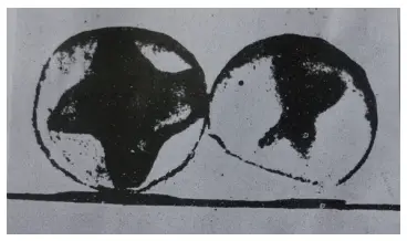
Figure 8 Cross-shaped segregation (3×)
The extent to which the eutectic carbides in high-speed steel (HSS) break down during the hot press process is referred to as carbide nonuniformity. The greater the deformation, the higher the degree of carbide fracture and the lower the level of carbide nonuniformity.
When the carbides in the steel are severely broken down, such as in the form of coarse ribbons, meshes, or large carbide buildup, it has a significant impact on the quality of the steel. It is therefore crucial to carefully control carbide nonuniformity to ensure the quality of HSS tools.
Figure 9 depicts the effect of carbide nonuniformity on the bending strength of W18 steel.
As can be seen from the figure, the bending strength in grades 7-8 with nonuniformity is only 40-50% of grades 1-2, reducing the strength to 1200-1500MPa, which is only equivalent to the level of higher toughness grades in cemented carbides. The horizontal performance is around 85% of the vertical performance.
The concentration and band-like distribution of carbides can also result in uneven quenched grains and uneven dissolution of carbides, leading to an increased tendency of overheating and a reduction in secondary hardening ability, respectively.
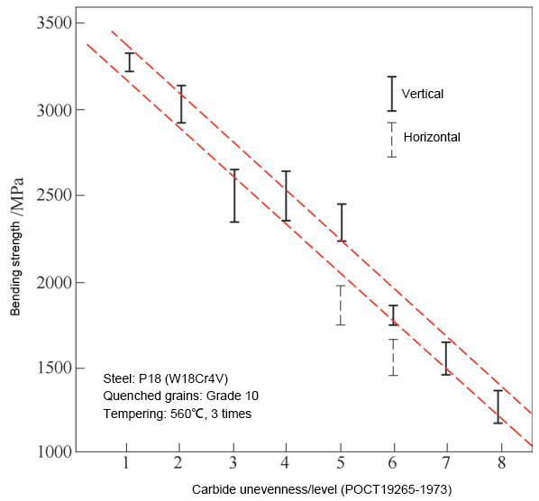
Figure 9 depicts the impact of carbide nonuniformity on the bending strength of W18Cr4V high-speed steel.
It can be seen that severe carbide nonuniformity can result in cracking and overheating during hot working, causing the finished tool to fail in use.
Figure 10 illustrates the quenching crack caused by coarse zonal carbides in W18 steel (etched with a 4% HNO3 alcohol solution).
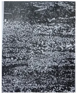
Figure 10 Coarse zonal carbide
Steel that has undergone hot rolling or annealing can form network carbides due to high heating temperatures, extended holding times that cause grain growth, and slow cooling processes that result in carbide precipitation along grain boundaries.
The presence of network carbides greatly increases the brittleness of the tool, making it more prone to chipping. In general, complete network carbides are not acceptable in steel.
The inspection for network carbides should be conducted after quenching and tempering.
Figure 11 shows the network carbides of T12A steel (etched with 4% HNO3 alcohol solution), while Figure 12 shows the morphology of the network carbides of 9SiCr steel (etched with 4% HNO3 alcohol solution), revealing severe overheating during the annealing process.

Figure 11 T12A Steel Mesh Carbide (500×)
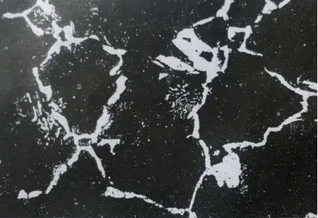
Figure 12 9SiCr Steel Mesh Carbide (500×)
Tool mills that perform HSS turning or milling may encounter a hard substance and sustain damage. This defect is typically not easily found during high-speed turning, due to the high cutting speed and noise.
However, during milling, lumps and strange chaos may be observed, such as a squeaking sound and severe burnout of the tool when milling slots with twist drills.
Upon inspection, bright blocks can be seen with the naked eye and have been found to have extremely high hardness, reaching 1225HV, while the non-hard areas are in a normal annealing state. This is referred to as a “caked mass”.
The presence of caked masses results in tool damage and makes cutting difficult.
The formation of these hard lumps is thought to be caused by the segregation of chemical components during the smelting process and may be a kind of high-hardness composite carbide or the result of the addition of refractory alloy blocks during smelting.
Figure 13 shows the macrostructure of a caked mass in W18 steel (etched by 4% HNO3 alcohol solution), with the white substance being the caked mass and the gray and black areas representing the bit grooves.
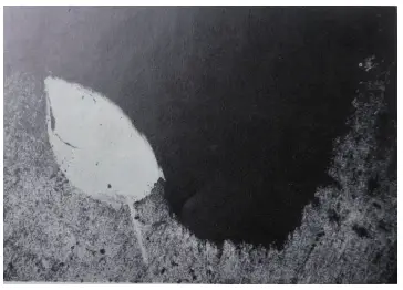
Figure 13 The macrostructure of W18 steel caked mass (20×)
Inclusions are a common defect in steel that can be classified into two categories: metallic inclusions and non-metallic inclusions.
Metallic inclusions form due to the incomplete melting of ferroalloy during the smelting process or the presence of foreign metal particles that remain in the steel ingot.
Non-metallic inclusions are divided into two types:
(1) endogenous inclusions, which are mainly caused by dirty pouring systems, peeling refractory mud from equipment, or using impure charge materials;
(2) inclusions produced and precipitated due to chemical reactions during the smelting process. Figure 14 shows metal inclusions found in W18 steel, while Figure 15 depicts non-metallic inclusions causing cracks during quenching (etched with 4% HNO3 alcohol solution).
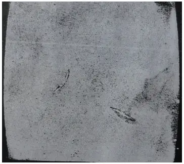
Figure 14 Metal inclusions
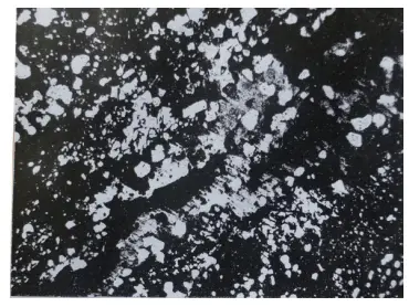
Figure 15 Cracking caused by non-metallic inclusions during quenching (400 x)
Inclusions are detrimental to the quality of steel. They segment the steel matrix, decrease its plasticity and strength, making the steel susceptible to cracking around the inclusions during rolling, forging, and heat treatment.
Inclusions can also cause fatigue in the steel, as well as difficulties during cutting and grinding. Therefore, tool steel must have specified requirements for inclusions.
In the process of steel smelting, uneven distribution of carbides can occur due to component segregation, or when carbides in the iron alloy are not fully melted, resulting in large angular carbides that persist without being crushed after forging.
The presence of these bulk carbides increases the tool’s brittleness and increases the risk of tipping.
During the heat treatment process, these large carbides and alloying elements can become enriched, potentially leading to defects such as overheating, insufficient tempering, and even cracking along grain boundaries.
Figure 16 shows overheating during quenching caused by segregation of surrounding components of large carbides (etched in 4% HNO3 alcohol solution).
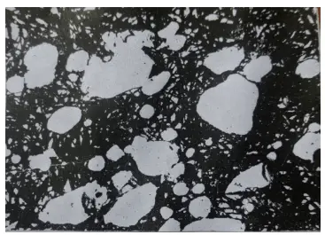
Figure 16 Overheating caused by segregation of components around bulk carbides during quenching (500×)
In the solidification process of liquid metal, segregation of carbon and alloying elements can cause large blocks of carbide to precipitate during cooling.
This segregation, known as liquation, is not easily eliminated during subsequent processing and results in the presence of bulk zoster carbide in the direction of the rolling of the steel.
Figure 17 shows CrMn liquation, as etched with a 4% HNO3 alcohol solution.
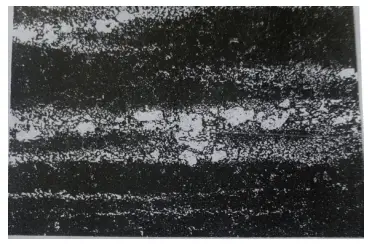
Figure 17 Carbide liquation (500×)
Steels with liquation are highly brittle, as the continuous metal matrix is disrupted, resulting in reduced strength. Previously, liquation was commonly found in CrWMn and CrMn steels, and using them to make gauges often resulted in difficulty in obtaining a smooth surface.
As the annealing temperature is too high and the holding time is too long, during the slow cooling process of the steel, carbides easily decompose into free carbon, known as graphite.
Figure 18 shows the microstructure of graphite carbon in T12A steel (etched with 4% bitter acid alcohol solution).
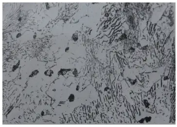
Figure 18 Graphitic carbon microstructure of T12A steel (500×)
The precipitation of graphite carbon significantly decreases the strength and toughness of steel, making it unsuitable for the production of knives and critical components. The steel exhibits black fractures when it contains high levels of graphite carbon.
The presence of graphite carbon can be determined through chemical analysis for both qualitative and quantitative analysis, and its shape and distribution can be observed through metallographic methods.
Additionally, there will be an increase in ferrite tissue around the graphite.
Mixing of materials in tool and mold manufacturing enterprises is a common problem, a result of poor management and a low-level defect. The mixed materials can include three aspects: mixed steel, mixed specifications, and mixed furnace numbers.
The last one is especially prevalent and can cause many issues with false heat treatments with no way to appeal. From time to time, unqualified tool material components are also encountered.
Some high-speed steel components do not meet the GB/T9943-2008 High-speed Tool Steel standard, especially regarding the high or low content of carbon. For example, W6Mo5Cr4V2Co5 belongs to the HSS-E type but has a lower carbon content than the standard lower limit.
Despite being labeled as high-performance HSS, after heat treatment, the hardness does not reach 67HRC. Steel mills must ensure that the steel can reach a hardness of at least 67HRC if they belong to the HSS-E type.
Whether a tool requires such high hardness is an internal matter for the tool factory and is not the responsibility of the steel mill.
However, if the hardness does not reach 67HRC, it is a fault of the steel mill. There are also many cases of unqualified die steel composition, leading to ongoing disputes.
The country has established standards for the decarburization of steel, however, steel suppliers often supply materials that exceed these standards, resulting in significant economic losses for tool manufacturing companies.
The surface hardness of tools decreases and their wear resistance is poor after quenching for materials with a decarburized layer. Therefore, it is necessary to completely remove the decarburized layer during machining to avoid any potential quality problems.
Figure 19 illustrates the decarburization morphology of W18 steel raw material (etched in 4% HNO3 alcohol solution). The decarburization zone is needle-shaped tempered martensite, while the non-decarburized zone is composed of quenched martensite, carbides, and retained austenite.
Figures 20 and 21 show the decarburization of M2 and T12 steel, respectively (etched in 4% HNO3 alcohol solution).
In the case of T12 steel, the fully decarburized layer is ferrite, the transition zone is composed of carbon-lean tempered martensite, and the non-decarburized zone is composed of tempered martensite and carbides.
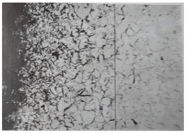
Figure 19 Austempered decarburization layer (250×)
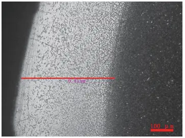
Figure 20 Decarburization of M2 steel
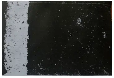
Figure 21 Decarburized layer of T12A steel (after quenching→tempering) (200×)
We selected a W18 steel flat bar with dimensions of 13mm x 4.5mm from a specific company and quenched it in a salt bath at temperatures of 1210℃, 1230℃, and 1270℃.
The heating time was 200 seconds, and the grain size was 10.5, as shown in Figure 22. The hardness after quenching was between 65 and 65.5HRC, but surprisingly, the hardness decreased after tempering at 550℃ for three times.
This anomaly is referred to as “an anecdote.
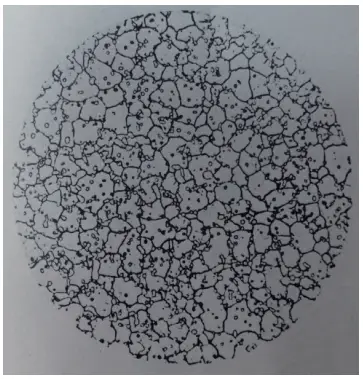
Figure 22 W18 steel quenching Grade 10.5 (500×)
It appears that the carbide is playing a trick on us, meaning that when the carbide is heated, it does not dissolve into austenite nor precipitate during the tempering process.
This is simply referred to as not being able to get in or out, so where’s the secondary hardening?
The root of the issue is that the carbide is teasing us, meaning that it doesn’t dissolve into the austenite during heating and there is no precipitation during the tempering process.
It’s simply a case of not being able to get in or out, so where’s the secondary hardening coming from?
Surface defects are easily visible with the naked eye, such as:
The specific impacts of steel defects on the physical properties of steel primarily include the following aspects:
Changes in hardness and plasticity: Influenced by certain factors, the strength of steel may increase, but at the same time, plasticity and toughness decrease, resulting in increased brittleness, a phenomenon known as hardening. This typically occurs under repeated loads, when the elastic limit increases and enters the plastic stage.
Effects on wear resistance and fatigue resistance: Surface quality defects not only affect the aesthetic appearance of hot-rolled strip steel, but can also have adverse effects on its mechanical properties and corrosion resistance, including wear and fatigue resistance.
Tool wear and unsmooth surfaces: The presence of looseness in the material can lead to excessive wear and unsmooth surfaces of the tools made from it. Hence, tool steel has strict requirements for the acceptable level of looseness.
Dispersion of microstructure and defects: The toughness of steel primarily depends on the dispersion of the microstructure and defects (avoiding concentrated defects), rather than the chemical composition. The toughness undergoes significant changes after heat treatment.
Effects of annealing and normalizing treatment: Annealing can reduce the hardness of steel, improve plasticity, refine grains, eliminate structural defects caused by casting, forging, and welding, homogenize the structure and composition of the steel, and relieve internal stress and work hardening in the steel. Normalizing has similar effects on large castings, forgings, and weldments.

As the founder of MachineMFG, I have dedicated over a decade of my career to the metalworking industry. My extensive experience has allowed me to become an expert in the fields of sheet metal fabrication, machining, mechanical engineering, and machine tools for metals. I am constantly thinking, reading, and writing about these subjects, constantly striving to stay at the forefront of my field. Let my knowledge and expertise be an asset to your business.