Orifice Flowmeters vs. Wedge Flowmeters: Understanding the Differences
How do you choose between an orifice flowmeter and a wedge flowmeter? Both serve to measure flow, but they have distinct advantages and drawbacks. Orifice flowmeters are known for their simplicity and durability, making them ideal for large pipelines. Wedge flowmeters, on the other hand, excel in handling high-viscosity fluids and dirty media with minimal clogging. This article will guide you through the key differences, helping you determine which is best suited for your application. Dive in to discover how each type can meet your specific needs and optimize your processes.
Orifice flowmeters and wedge flowmeters belong to the constant cross-section, differential pressure type of flowmeters. In other words, they share the same concept.
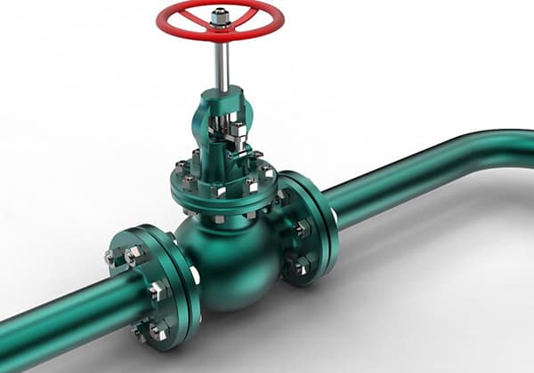
An orifice flowmeter involves inserting a circular plate with a hole in the middle into a pipeline, and then measuring the pressure difference of the steam before and after the orifice plate. The steam flow rate is then calculated based on this data.
As the steam flow rate is constricted at the orifice plate, the static pressure decreases and the flow rate increases, resulting in a pressure difference before and after the orifice plate. According to the continuity equation (law of conservation of mass) and the Bernoulli equation (law of conservation of energy), the flow rate is proportional to the pressure difference: M2∝ΔP, where M is the flow rate and ΔP is the pressure difference.
The pressure difference signal is transmitted to a differential pressure transmitter via impulse lines, and then sent to a flow integrator, which calculates the flow rate based on the pressure difference signal. Additionally, the temperature and pressure of the steam are measured by temperature and pressure sensors, and the flow integrator calculates the compensated flow rate based on the current temperature and pressure.
A wedge flowmeter works by constraining the fluid flow with a wedge, creating a pressure difference upstream and downstream of the wedge that is proportional to the square of the flow rate. This pressure difference is taken from two pressure taps on either side of the wedge and sent to a differential pressure transmitter to convert it into an electrical signal output. This signal is then processed by a specialized flow integrator to determine the flow rate.
Why choose an orifice flowmeter
Advantages:
The structure of the throttling device is easy to replicate, simple, robust, and has stable and reliable performance, with a long service life.
It is suitable for measuring larger diameter pipelines (currently orifice flowmeters are generally the only choice for pipelines with a diameter greater than DN 600 mm).
Durable and long-lasting.
Comprehensive calibration.
Affordable price.
Disadvantages:
High requirements for the installation of the throttling device, impulse lines, and condensate pots, making installation more complex.
It is difficult to calibrate the entire orifice flowmeter as a whole. Currently, only the differential pressure sensor, pressure sensor, and temperature sensor can be calibrated individually, making it difficult to ensure overall accuracy.
The structure of the orifice plate causes a significant reduction in static pressure and a significant increase in flow rate, leading to severe erosion of the orifice plate, and a decrease in accuracy over time. In the case of measuring the flow rate of liquefied gas, propylene, and other easily vaporized liquids, changes in the physical properties of the fluid can cause even more severe erosion of the orifice plate.
The structure of the orifice plate results in a significant static pressure loss after the fluid passes through, making the orifice flowmeter a high-energy-consuming instrument. This increases the loss of mechanical power for pumps and motors, which is not conducive to improving the energy efficiency of the system and is a disadvantage for increasingly strict energy-saving requirements.
Why choose a wedge flowmeter
Advantages:
Particularly suitable for measuring media with high viscosity, low Reynolds number, suspended particles, or bubbles.
Measurement accuracy is not affected by the dielectric constant or other properties of the fluid.
The special design of the wedge-shaped component has a deflection effect to prevent clogging.
Compensation function for changes in fluid viscosity, temperature, density, etc.
Vibration-resistant, shock-resistant, dirt-resistant, and corrosion-resistant.
Has bidirectional flow measurement function.
Energy-saving and emission reduction: Wedge flowmeters have a simple, robust structure, high reliability, easy installation, and low operating and maintenance costs.
No moving parts or wear, and no need for recalibration during long-term use.
Disadvantages:
Compared with orifice flowmeters, wedge flowmeters have the disadvantages of higher price and requiring individual calibration for each unit. In terms of design, manufacture, calculation, installation, and use, wedge flowmeters still lack corresponding data and standards.
Summary: Currently, wedge flowmeters and orifice flowmeters coexist and play to their respective strengths. However, in the long run, wedge flowmeters are the development trend of the new generation of differential pressure flowmeters.
Precautions for installing
10 precautions for installing an orifice flowmeter:
Before installing the instrument, the process pipeline should be blown clean to prevent ferromagnetic substances from adhering to the instrument, which could affect the instrument’s performance or even damage it. If unavoidable, a magnetic filter should be installed at the inlet of the instrument. The instrument itself should not be blown with air before being put into operation to avoid damage.
The instrument should be checked for damage before installation.
The installation of the instrument can be vertical or horizontal. If installed vertically, the angle between the instrument’s centerline and the vertical line should be less than 2°. If installed horizontally, the angle between the instrument’s horizontal centerline and the horizontal line should be less than 2°.
The upstream and downstream pipelines of the instrument should have the same diameter as the instrument. The flanges or threads used to connect the pipeline should match the instrument’s flanges and threads. The upstream straight pipe section should be at least five times the nominal diameter of the instrument, and the downstream straight pipe section should be greater than or equal to 250mm.
Since the instrument’s signal is transmitted through magnetic coupling, there should be no ferromagnetic substances within 250px around the installation to ensure the instrument’s performance.
If the instrument measures gas, it is calibrated at a specific pressure. If the gas is directly discharged into the atmosphere from the instrument’s outlet, it will cause a pressure drop at the float and distort the data. If this is the case, a valve should be installed at the instrument’s outlet.
The instrument installed in the pipeline should not be subjected to stress. The inlet and outlet of the instrument should have suitable pipe supports to keep the instrument in a minimum stress state.
When installing an instrument with a PTFE lining, special care should be taken. Under pressure, PTFE will deform, so flange nuts should not be tightened too tightly.
Instruments with LCD displays should be installed to avoid direct sunlight hitting the display and reducing the life of the LCD.
When measuring low-temperature media, a jacketed type should be selected.
28 precautions for installation of orifice plate flowmeter
The orifice plate flowmeter should not be installed on the formed pipeline.
Attention should be paid to the straight pipe section length before and after the flow meter.
For electromagnetic and mass flow meters with grounding requirements, grounding should be performed according to the instructions.
During the pipeline welding process, the grounding wire should avoid the instrument body to prevent grounding current from flowing through the instrument body and damaging the instrument.
During the process welding, the grounding current should not pass through the capillary pressure tube of the single or double flange instrument.
For the medium and high pressure pressure guiding tubes, argon arc welding or socket welding can be used. For wind speeds >2m/s, windproof measures should be taken. If the wind speed is >8m/s, welding should be stopped.
Pay attention to the installation direction of the pressure tapping device of the orifice plate flowmeter.
Stainless steel pressure guiding tubes are strictly prohibited from being heated or flattened.
The installation position of the instrument pressure guiding tube, air duct, and wire-through tube should avoid hindering the process production operation in the future, avoid high-temperature and corrosive places, and should be firmly fixed. The lowest end of the wire-through tube from top to bottom should be lower than the wiring inlet of the connected instrument. Y-shaped or cone-shaped explosion-proof sealing joints should be added near the instrument side. The lowest point of the main air duct of the instrument should have a condensation (pollution) valve.
Copper gaskets used in instruments should be annealed before use, and attention should be paid to the allowable temperature, medium, and pressure conditions of various material gaskets.
Different grounding systems cannot be mixed in the instrument junction box. The shielding wires of all instruments should be connected separately to the upper and lower shielding layers and should not be twisted together.
If the instrument is in an inconvenient observation and maintenance position, change its position or install a platform.
There should be no joints in the instrument wires, and hidden records should be made. Welding or pressure connections should be used for compensating wire joints.
Stainless steel welds should be pickled, passivated, and neutralized.
For instruments and fittings that require degreasing, degreasing should be strictly performed according to specifications. After degreasing, the sealing and storage of instruments and fittings should be carefully done to prevent secondary pollution during storage and installation.
Stainless steel pipelines are strictly prohibited from direct contact with carbon steel.
Galvanized and aluminum alloy cable trays are strictly prohibited from electric welding, gas cutting, and punching. Mechanical cutting and punching tools such as saw blades and special punching machines should be used instead.
Stainless steel pipes are strictly prohibited from electric welding, gas cutting, and punching. Plasma or mechanical cutting and punching should be used instead.
For instrument wire-through pipes in explosion-prone areas, the electrical continuity should be maintained. Conductive paste should be used for the thread of the grounded instrument wire-through pipe. The thread of the wire-through pipe less than or equal to 36V should be rustproofed at least. The exposed thread should not be greater than one thread.
For explosion-proof areas, instrument wire-through pipes should maintain electrical continuity.
The insulation resistance of instrument lines below 100V should be measured with a 250V shake meter, and it should be ≥5 megohms.
Aluminum alloy cable trays should be connected with short-circuit wires, while galvanized cable trays should have at least two anti-loose screws tightened. For cable trays shorter than 30 meters, both ends should be reliably grounded, and for those longer than 30 meters, a grounding point should be added every 30 meters.
When different grounding systems’ instrument lines or instrument lines sharing the same cable tray, a metal partition should be used to separate them.
It is strictly prohibited to use gas welding methods during the installation and processing of instrument panels, cabinets, boxes, and tables. Welding should not be used for installation and fixing, and mechanical punching methods should be used for opening holes.
The blind end of the instrument heat tracing and return should not be larger than 100mm.
A pipe cap should be added to the discharge port of the transmitter’s drain valve to prevent valve leakage, especially in explosion-proof areas.
One end of the instrument and its cable tray, impulse pipe, and pressure pipe should be fixed in the thermal expansion area (such as towers and accessories that move with thermal expansion of the tower), and the other end should be fixed in the non-thermal expansion area (such as labor protection rooms). When connecting the instrument, flexible pipes, cable trays, and impulse pipes should be left with a certain thermal expansion allowance according to the actual situation on-site.
Cable trays and conduit attached to the tower should be equipped with thermal expansion joints or flexible connections according to the actual situation on-site.
4 precautions for installation and use of wedge flow meters:
Install according to the direction indicated on the wedge flow meter
Although some articles and materials claim that there is no direction requirement for installing wedge flow meters and that they can be used for measuring reverse flow, the measurement principle of wedge flow meters shows that if a standard V-shaped wedge is used, the throttling of the fluid is the same for both forward and reverse flow.
However, manufacturers label the direction of fluid flow on the body of the wedge flow meter. Looking at the two end flanges of the wedge flow meter, the installation position of the wedge is not in the center of the wedge flow meter.
Therefore, it is important to install the wedge flow meter in the direction indicated on the device to avoid increased measurement errors caused by incorrect installation direction.
Direction of pressure tapping interface
According to the pressure tapping guidelines for measuring instruments, when measuring gas flow, the pressure tapping interface is located in the middle and upper part of the throttling element, when measuring liquid flow, the pressure tapping interface is located in the middle and lower part of the throttling element, and when measuring dirty and contaminated media, the pressure tapping interface is located in the middle of the throttling element.
However, the wedge block of the wedge flow meter is not evenly distributed in the inner chamber of the device, and the position of the pressure tapping interface has been preset by the manufacturer, located above and below the wedge block welding on the device.
If the pressure tapping interface is installed in the middle and lower part of the pipeline when measuring liquid, the wedge block inside the wedge flow meter is also located in the middle and lower part of the pipeline.
This means that fluid has to flow from the upper part of the wedge flow meter, which may cause impurities to settle at the bottom of the device, leading to the risk of blocking the pressure tapping interface in front of the wedge block and causing measurement failure. Therefore, during installation, it is necessary to differentiate according to the actual situation.
Vertical Pipeline Installation
Vertical installation of wedge flow meters makes zero calibration difficult.
It is recommended to install the wedge flowmeter horizontally and minimize the use of vertical installation because the zero point calibration of the wedge flowmeter is difficult to perform in a vertical installation.
The zero point calibration of the wedge flowmeter requires the process medium to fill the wedge flowmeter. After closing the valves before and after the pipeline, the flowmeter should be calibrated while ensuring that the process medium inside the wedge flowmeter is in a static state.
Since the flow measurement instrument of the throttling element generally does not design a secondary line removal facility, there are generally no process cut-off valves before and after the throttling element. In this situation, the calibration of the wedge flowmeter is more difficult.
If the wedge flowmeter is installed horizontally, we can assume that the static fluid does not have an additional effect on the differential pressure detected by the wedge flowmeter.
Therefore, we only need to close the front and rear pressure taking valves of the wedge flowmeter and vent them to the atmosphere to achieve zero point calibration of the flowmeter.
If the wedge flowmeter is installed vertically, a static static pressure will be generated in the wedge flowmeter cavity, which will increase the differential pressure transmitter’s differential pressure value in the positive pressure chamber and cause the zero point differential pressure value of the wedge flowmeter to be non-zero.
Also, static pressure errors will be generated in the negative pressure measurement reference pressure pipe. Therefore, the calibration of the zero point is difficult at this time.
Even with a double flange transmitter, we can calculate the static pressure added by the negative pressure measurement, but we can only calculate the density of the measured medium based on the ideal value during design.
Roughly calculating the static pressure inside the wedge flowmeter and making calibration revisions will reduce the reliability of the zero point.
Therefore, in practical installation, it is best not to install the wedge flowmeter vertically. If the process cannot meet the requirements for horizontal installation, in addition to ensuring that the wedge flowmeter is filled with process medium, we must also accurately calculate the modified pressure difference of the zero point during the vertical installation. We cannot simply close the positive and negative pressure taking valves and perform zero point calibration.
Installation of Drainage and Pressure Relief Valve
Installing a drain valve with the wedge flowmeter makes maintenance and repair work much more convenient.
In the wedge flowmeter + double flange transmitter flow measurement mode, a drainage and pressure relief valve must be installed between the pressure taking valve and the double flange connection part.
This valve is very important. During the flowmeter calibration process, it can ensure that the pressure between the positive and negative flanges is consistent with atmospheric pressure to ensure the reliability of the calibration and also ensure the safety of maintenance personnel.
If the double flange transmitter is damaged and needs to be replaced, the drainage and pressure relief valve can determine whether the pressure taking valve is leaking.
Only when safety is ensured can the double flange transmitter be removed. Many engineering installations omit the installation of the drainage and pressure relief valve, which is incorrect and must be rectified.
Summary: Regardless of the type of flow meter, installation and usage should be performed according to the manufacturer’s instructions and in consideration of its unique characteristics.
The orifice flowmeter can be widely used for continuous measurement of the volumetric flow or mass flow of various liquids, gases, natural gas, and steam in industries such as petroleum, chemical, natural gas, metallurgy, electric power, pharmaceuticals, food, pesticides, and environmental protection.
The wedge flowmeter is a new type of throttle differential pressure flow measurement instrument.
It can accurately measure the flow rate in high viscosity, low Reynolds number, and Reynolds number of 500 fluids, and has unparalleled advantages and irreplaceable roles in flow measurement applications with low flow velocity, small flow rate, and large pipe diameter.
In the petrochemical/coal chemical industry, wedge flowmeters are commonly used in:
Refining units and ethylene plants
High viscosity and dirty media
High temperature, high pressure, and highly abrasive media
Coal-water slurry (black water, ash water), oil-coal slurry, etc.
As the founder of MachineMFG, I have dedicated over a decade of my career to the metalworking industry. My extensive experience has allowed me to become an expert in the fields of sheet metal fabrication, machining, mechanical engineering, and machine tools for metals. I am constantly thinking, reading, and writing about these subjects, constantly striving to stay at the forefront of my field. Let my knowledge and expertise be an asset to your business.
Attention all mechanical engineers and manufacturing professionals! Are you struggling with pesky anodizing defects in your aluminum products? Look no further! In this blog post, we'll dive deep into the…
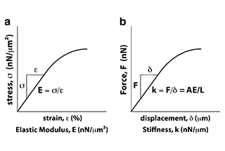
Ever wondered why some materials bend easily while others remain rigid? This blog dives into the fascinating world of elastic modulus and stiffness, unraveling their crucial roles in engineering. By…
Have you ever wondered what makes a perfect circle? In the world of mechanical engineering, roundness is a crucial concept that affects the performance and longevity of rotating components. This…
In today's fast-paced manufacturing world, efficient deburring is crucial. With numerous methods available, choosing the right one can be daunting. In this blog post, we'll explore various deburring techniques, from…
Have you ever wondered what keeps the world spinning smoothly? The unsung heroes behind the scenes are bearings. These small but mighty components play a crucial role in reducing friction…
Gears are the unsung heroes of the mechanical world, quietly working behind the scenes to keep machines running smoothly. But have you ever wondered what materials these critical components are…
This article explores the top 5 cooling tower manufacturers shaping our world. Learn how these companies innovate to keep industries running smoothly and efficiently. Get ready to uncover the secrets…
Have you ever wondered what keeps our gas systems running smoothly and safely? In this article, we explore top gas regulator manufacturers, uncovering their innovations and contributions to the industry.…
Ever wondered why connecting copper and aluminum wires is problematic? This article explains the risks associated with connecting these two metals due to their differing electrochemical properties, which can lead…