Copper Busbar Selection and Fabrication: Expert Guide for Mechanical Engineers
Ever wondered how to choose the right copper busbar for your electrical systems? This article breaks down the essentials of copper busbar selection and fabrication, ensuring your electrical setups are both efficient and safe. Learn the key criteria and steps to make informed decisions.
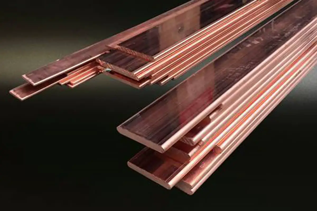
1. Rectangular copper busbars should be used as much as possible for primary wiring.
When it is difficult to process with rectangular busbars or the current is less than or equal to 100A, insulated wires can be used.
Copper busbars are generally used for machine room type distribution cabinets.
2. Selection of the primary busbar:
2.1 If there are requirements in the drawings, the busbar should be selected according to the requirements of the drawings (the busbars of the main incoming line cabinet and the contact cabinet are selected according to the confluence).
When there are no specific requirements in the drawings, the busbar should be selected in accordance with the provisions of this process code.
2.2 The selection of branch busbars should generally be based on the rated working current of the thermal trip unit of the automatic air switch. Other selections should be made according to Table 1.
Table 1 Requirements for Busbar Selection
Form
Conditions for Choosing a Busbar
Automatic air switch without thermal release.
According to the rated current value of the air switch.
There are several branch circuits below the automatic air switch, each equipped with their own automatic air switches.
According to the branch circuit current value.
The circuit consists of a knife switch, a fuse, and a current transformer.
Based on the rated current value of the primary side of the current transformer.
Only contactor
Based on the rated current value of the contactor.
Only fuse
According to the fuse’s rated current value.
Explanation: When adjusting the thermal trip unit of a molded case circuit breaker, select according to the maximum value.
3. Busbar Current Carrying Capacity
3.1 The busbar of the 8PT cabinet is selected according to the cross-section specified in the technical busbar material table. For parts not specified by the material, use Table 2 for selection:
Table 2 Current carrying capacity selection for non-standard busbars in 8PT cabinet.
Rated Current (A)
Copper Busbar
Hard Busbar
Soft Busbar
160
2*20*1
175~225
20*5
225~250
25*5
4*20*1
250-275
30*5
275~350
40*520*10
350-400
30*10
5*32*1
400~500
30*10
500~630
40*10
8*40*1
3.2 For standard products, refer to the company’s busbar selection chart:
3.3 The cross-section of the protective conductor should be chosen according to Table 4. If the wire selected according to Table 2 is not a standard size, it should be adjusted to standard busbar specifications.
Table 3
Cross-sectional area S (mm2)of the device’s phase line
The minimum cross-section of the corresponding PE protective conductor Sp (PE, PEN) mm2.
≤16
S
16<S≤35
16
35<S≤400
S/2
Note 1: When the protective conductor is used as PEN, it is permissible as long as the neutral conductor current does not exceed 30% of the phase current. When it exceeds 30% of the phase current, the cross-section of the corresponding protective conductor needs to be increased. The PEN protective conductor bar does not need insulation.
Note 2: When the non-standard cross-sectional dimensions are obtained from this table, the next larger size should be selected.
3.4 The color of the busbar and wires in the device should comply with the provisions of GB2681-81 “Wire Colors in Electrical Equipment Sets”, and its phase sequence is shown in Table 4 (viewed from the front of the cabinet).
Table 4: Busbar Arrangement Sequence
Category
Signs
Vertical Arrangement
Horizontal Arrangement
Arranged from front to back
Alternating Current
Phase A L1
Yellow
Top
Left Center Right Far Right Far Right
Far
Phase B L2
Green
Middle
Left
Medium
Phase C L3
Red
Bottom
Center
Near
Neutral Line N
Light Blue
Lowest
Right
Nearest
Protective Earth Neutral Line PEN
Yellow-Green Alternating
Lowest
Far Right
Nearest
Protective Line PE
Yellow-Green Alternating
–
–
–
Direct Current
Positive Terminal L+
Brown
Top
Left
Far
Negative Terminal L-
Blue
Bottom
Right
Near
Ground Neutral M
Light Blue
–
–
–
Explanation: The arrangement order of the 8PT product busbar refers to the standard order generated by the 8PT software.
3.5 Busbar Phase Sequence Identification:
The main busbar phase sequence identification can be marked with color labels and printed labels. The color labels are the preferred method. When using printed labels, the print should be clear, neatly pasted, and firmly attached.
When using color labels, the color of the labels should comply with the specifications in Table 5.
The PE busbar is marked with a yellow-green dual color and a PE symbol. The dimensions of the color labels are specified in Table 5.
Table 5 Diameter of color labels
Busbar Width
Color Mark Diameter
15mm
φ15
20, 25, 30, 40, 50mm
φ20
60, 80, 100, 120
φ30
Explanation: The busbars of the 8PT are wrapped and labeled with L1, L2, L3, N and yellow-green dual-color identification strips.
3.6 The minimum distance between the horizontal and vertical arrangement of the busbar and the bottom of the structure should not be less than 200mm, including N and PE rows.
3.7 When N and PE rows use M8 or larger bolts for incoming and outgoing wires, punched holes are configured with external hex screws; when using M6 bolts, punched holes are configured with internal hex screws.
3.8 The arrangement of the busbars must ensure the operating space of the direct operating electrical equipment (that is, the busbars should not jeopardize the operator’s safety during normal operation).
II. Busbar Processing Steps
1. Select lines according to the drawing (those not specified in the drawing are selected according to this process), and determine the wiring scheme size.
The shape and size of the busbar are generally determined by the processor, and standard products and drawings with special requirements are made according to the drawings.
2. Cut the material, adjust the busbar to be straight and level.
3. Mark lines, drill holes or punch holes, deburr, and chamfer the end faces.
Note: For some special bus bar sizes that are difficult to measure and process, an additional 150mm length can be reserved, bending can be performed and then holes punched.
6. Bus bar manufacturing requirements
6.1 The production of bus bars should consider safety and reliability after installation, convenience for inspection, and dismantling.
6.2 The bus bar itself must be very straight, and any bent or uneven bus bar materials should be corrected. Generally, a straightening machine is used for correction or manually corrected using a wooden hammer.
However, bus bars corrected in this manner should not have any obvious hammer marks. After correction, the bending degree of the wide surface of the bus bar should not exceed 2mm per meter, and the side should not exceed 3mm per meter.
6.3 The processed parts of the bus bar should have no burrs, and the end face should be perpendicular to the edge of the bus bar (except for special requirements). The bus bar should be deburred on both sides after punching.
6.4 When it is necessary to connect secondary power wires on the primary copper bus bars, drill a Ф6 hole on the bus bar and connect it with an M5 screw. The Ф6 hole is drilled 30mm away from the bus bar joint and 8mm from the edge. Strip a 15×15mm bare surface from the bus bar fitted with a heat shrink sleeve for wiring.
6.5 Refer to the “Main Circuit Primary Process Guidelines” bus bar punching table for the bus bar joint punching size, which mainly includes straight and vertical connections. When the distance between bus bars exceeds the length in Table 6, an additional fixed support should be added.
Table 6
Busbar Width (mm)
Support Distance (mm)
≤30
300
≤50
600
≥60
900
6.6 The distance from the starting point of the busbar bend to the closest edge of the busbar support clamp should not be less than 50mm, and should not exceed 0.25L (L is the distance between two support points of the busbar, usually 1m), see Figure 1.
6.7 The distance from the starting point of the busbar bend to the busbar overlap position should not be less than 20mm, see Figur e 2.
Figure 1 Vertical bending
a refers to the width of the busbar
Figure 2 Flat Bend
b refers to the thickness of the busbar
6.8 The busbar can be bent flat, vertically, or twisted as needed. The radii for flat and vertical bends should be made in accordance with the values listed in Figures 1 and 2, and Table 7.
6.9 Processing of Rectangular Busbar at 90 Degrees
When twisting a busbar at 90 degrees, operations can be conducted on a bench vise. Place a copper block on the jaws of the vise, clamp the starting end of the busbar to be bent vertically between the jaws, use an adjustable wrench or other specialized tools to rotate the busbar 90 degrees at an appropriate location.
The minimum twisting distance for the busbar is 1.5 to 2 times the width (b) of the busbar. The specifications for this process are a thickness of ≤6mm and a busbar width of ≤60mm. The specific form can be seen in Figure 3.
Figure 3. Twisted 90° busbar bend
6.10 The start and end points of the flat bend, upright bend, and twisted bend of the three-phase busbar in the same circuit should be consistent.
6.11 When multiple rectangular busbars are used in parallel for one circuit, there should be a gap no less than the thickness of the busbar between the pieces.
6.12 Processing details:
Processing steps:
Measure → Cut → Straighten, Level → Mark → Punch → Bend → Outsource Surface Tin Plating → Install → Paste Label
Note:
① Process the 8PT copper bar according to the standard drawings formed in the 8PT software, and corrections need to be made for those required to be positively overlapped by the technical agreement.
② Measure the copper bar by finding a fixed point in the cabinet, and do not forget the thickness dimension of the copper bar.
—Copper bar diagram: Generally, three views are used, in projection method—main view, top view, left view.
—Technical requirements to be marked on the copper busbar processing diagram:
①. Unit: ** mm
②. Specification: ** × ** width * thickness
③. Tolerance: +/-0.3mm
④. Quantity: ** pieces
⑤. Installation location:
—Unfolding material calculation:
1). Bend right angle bend :
①. The basic rule for bending a right angle bend is: Unfolded material length = overall outside measurement length – bar thickness*1.77 (mm).
②. For a right angle bend busbar with a thickness of less than 6mm, use an R5 mold to bend, and for those above 6mm, use an R10 mold to bend.
③. Specific reduction coefficient (each right-angle bend outside dimension is measured once and the coefficient is reduced once), see Table 8:
Table 8
Busbar Material Thickness (mm)
Required Dimension Reduction (mm)
Busbar Material Thickness (mm)
Required Dimension Reduction (mm)
3
5.3
6
10.6
4
7.1
8
14.2
5
8.9
10
17.7
2) Oblique Bend:
Calculated according to the Pythagorean theorem, with slight deviations.
Figure 4 Busbar Diagram
Key Points to Note:
—There should be no burrs on the cross-section of the copper busbar.
—There should be no burrs on the edges of the punched holes.
—There should be no marks left from marking pens on the surface of the copper busbar during installation.
—When applying a heat-shrink sleeve to the busbar surface, use a hot air gun to heat it evenly. There should be no uneven heating pits on the surface.
—When stripping the heat-shrink sleeve, use a square ruler to press down on the paper knife and strip it in a straight line. The tin-plating layer on the copper busbar surface should not be scratched, exposing traces of bare copper.
—Consider the electrical clearance and creepage distance between busbars and from the busbar to the ground during busbar processing.
7. Busbar Installation
7.1 The busbar connection method should be executed according to the overlap table specified in the process document.
7.2 In the switchgear, the busbar is generally connected with through bolts. The busbar connection should be tight and have good contact. The connection surface should naturally fit together, and the configuration should be neat and aesthetically pleasing.
7.3 The fasteners used for busbar connections should be galvanized bolts, nuts, spring pads, and washers that comply with national standards. The 8PT product connection meets the relevant process requirements.
7.4 All overlay bolts should use ordinary flat washers (concave surface facing the busbar). The threaded part of the bolt should protrude by 3~5 threads. There should be a clear distance of more than 3 mm between adjacent bolt washers.
7.5 When the busbar is laid flat, the bolts should be installed according to the following rules for easy observation of the tightening condition and maintenance: facing the electrical maintenance and operating side, the through bolts should be installed from back to front and from bottom to top. In other cases, the nut should be on the maintenance side.
7.6 After the busbar is installed, if there is sagging or rising between two support points, the deviation should not be more than 4mm.
7.7 The connection between busbars should ensure sufficient and lasting contact stress, but it should not cause permanent deformation of the busbar.
7.8 A copper-aluminum composite piece should be installed when copper and aluminum are connected.
Precautions:
—The copper busbar needs to be protected during the tin-plating process. It must pass inspection to confirm that the surface treatment is acceptable before it can be transported or installed.
—White gloves must be worn when installing the copper busbar after tin-plating to prevent fingerprints from being left on the surface.
—Ordinary products are installed with 4.8-grade bolts, while Siemens products and other specified products are installed with 8.8-grade bolts.
—The bolt penetration of the 8PT product should be in accordance with the assembly diagram of the 8PT product, and the torque should meet the requirements.
—Electrical clearance and creepage distance between busbars and from the busbar to the ground.
8. Inspection
8.1 Whether the manufacture of the primary line meets the relevant requirements of the drawings.
8.2 Whether the primary busbar and selection meet the load capacity requirements.
8.3 Whether the electrical clearance and creepage distance of the busbar meet the process requirements.
As the founder of MachineMFG, I have dedicated over a decade of my career to the metalworking industry. My extensive experience has allowed me to become an expert in the fields of sheet metal fabrication, machining, mechanical engineering, and machine tools for metals. I am constantly thinking, reading, and writing about these subjects, constantly striving to stay at the forefront of my field. Let my knowledge and expertise be an asset to your business.
Have you ever wondered which cable is better: copper or aluminum? This article dives into a detailed comparison of copper and aluminum cables, highlighting their advantages and disadvantages. From resistivity…
Why is the debate between aluminum alloy and copper conductors so critical in the electrical industry? As materials for conductors, both have unique benefits and drawbacks. This article explores the…
Ever wondered how busbars, the unsung heroes of electrical distribution, are processed and installed? This article delves into the intricate steps of busbar selection, preparation, and installation, ensuring efficient and…
How do you transform raw copper and aluminum into critical components for electrical systems? This article delves into the intricate processes behind busbar fabrication, detailing the techniques and tools necessary…
Ever wonder what it takes to ensure a flawless busbar installation? This comprehensive guide will walk you through each step, from technical preparations to the final adjustments, ensuring your project…
What makes busbars crucial in electrical systems? Busbars, key components in substations and distribution systems, efficiently transmit electrical energy. This article explores their function, various types like rectangular and tubular,…
Are you aware that improper installation of busbars can lead to costly and dangerous electrical failures? This article details the comprehensive standards for installing and inspecting busbars, including support brackets,…
Ever wondered if aluminum bus bars can match the performance of copper while costing less? This article explores the key differences between aluminum and copper bus bars, comparing their conductivity,…
How can you ensure the safe and efficient installation of bus ducts in your facility? This guide covers everything from preparing materials and equipment to detailed steps for installing enclosed…