How can you ensure the safe and efficient installation of bus ducts in your facility? This guide covers everything from preparing materials and equipment to detailed steps for installing enclosed and plug-in bus ducts. You’ll learn key techniques for unpacking, fabricating brackets, installing supports, and testing the system. By following these instructions, you’ll be able to prevent common issues, maintain safety standards, and ensure a smooth operational setup. Dive in to discover practical tips and expert advice for a successful bus duct installation project.
2) Various specifications of steel profiles, clamps, all kinds of bolts, washers, etc.
3) Camphor, paint, welding rods, etc.
2. Equipment Preparation
1) Main installation equipment: hydraulic elevating truck, scaffolding, hoisting machine, pulley, large rope, bench vise, steel saw, hammer, electric drill, electric hammer, welding machine, hydraulic pipe bender, adjustable wrench, manufacturer’s special tools, torque wrench, etc.
2) Main testing equipment: steel square, steel tape measure, level, insulation resistance tester, etc.
3. Working Conditions
1) The indoor locations suitable for the installation of enclosed and plug-in bus ducts are already dry, and all the architectural decoration work at the installation site should be completed, with all doors and windows in place.
2) The installation of indoor enclosed bus ducts should be carried out after the basic construction of pipelines and air conditioning works is completed to prevent damage to the bus ducts during the construction of other specialties.
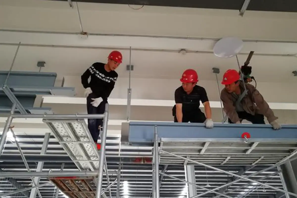
3) The scaffolding for high-altitude work has been set up and accepted by the safety technology department.
II. Construction Process
1. Process Flow
Equipment unpacking check
→ Bracket fabrication and installation
→ Enclosed, plug-in bus duct installation
→ Power-on testing and inspection
2. Construction Key Points
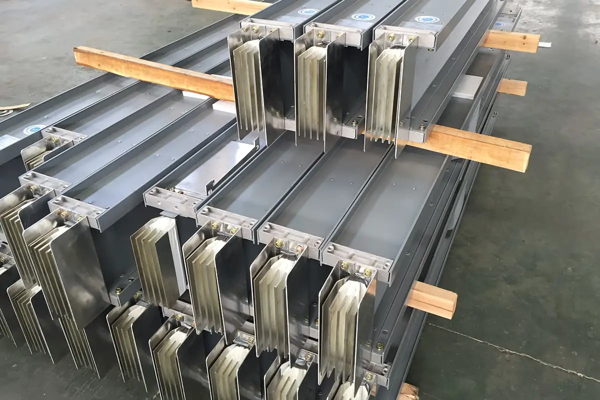
1) Bus Duct Unpacking Inspection
① Enclosed and plug-in bus ducts should come with a factory certificate of conformity and installation technical documents. The technical documents should include rated voltage, rated capacity, test reports, and other technical data.
② The packaging and enclosure should be in good condition, the bus duct specifications should meet the requirements, and all kinds of steel profiles, clamps, various bolts, washers, and other accessories should be complete.
③ Each section of the enclosed bus duct supplied in the set should be clearly marked, with complete accessories, no deformation of the shell, and no internal damage.
④ The bolted overlapping surface of the enclosed and plug-in bus ducts should be tin-plated. The overlapping surface should be flat, and the tin layer should not have a pitted surface, peeling, and uncovered parts.
⑤ The inner surface of the enclosure and plug-in bus duct shell should be painted with matte black paint, and the outer surface should be painted with light-colored paint.
2) Bus Duct Bracket Fabrication
The form of the bus duct bracket is determined by the installation method of the bus duct. There are three installation methods for the bus duct: vertical installation, horizontal side installation, and horizontal suspension installation.
Brackets can be supplied by the manufacturer according to user requirements or can be self-made. The fabrication and installation of brackets should be carried out according to the design and product technical documents. If there are no provisions in the design and technical documents, they can be fabricated and installed according to the following requirements.
Brackets should be made of angle steel, channel steel, or flat steel according to the structural type of the construction site. The preferred forms are “I” type, “U” type, “L” type, and “T” type.
Brackets should be processed according to the selected model and measured dimensions. The cut-off of angle steel and channel steel must be sawn or punched, and chamfering is required. Use of electric and gas welding cutting is strictly prohibited. The maximum processing size error should not exceed 5mm.
Bracket drilling should use a bench drill or a hand drill. The hole diameter should not exceed the diameter of the fixing bolt by 2mm. Use of electric and gas welding to cut holes is strictly prohibited.
Hanger rod threading should be processed using a threading machine or die. Cross threading or thread breakage is not allowed, or a threaded rod can be used instead of a threaded hanger rod.
Metal brackets and accessories fabricated on-site should be galvanized or painted as required. In places where conditions are not available or requirements are not high, camphor and gray paint can be applied.
3) Installation of Busbar Supports and Hangers
The installation location of enclosed and plug-in busbar brackets should be determined according to the needs of busbar layout.
When the enclosed and plug-in busbar straight sections are laid horizontally, they should be fixed with brackets or hangers. The spacing between the fixed points should comply with the design requirements and product technical document regulations, generally 2~3m, and it is advisable to be 2m for currents over 1000A.
When the enclosed and plug-in busbar is fixed vertically along the wall, a fixed bracket should be used. For the vertical installation of enclosed and plug-in busbars on the building’s floor slabs, spring brackets should be used for support. For enclosed and plug-in busbars with smaller current capacity (400A and below), spring brackets can be set on the floor slabs every other layer, and for 400A and above, they need to be supported on each layer.
Supports must be added at the corners and box (panel) connection points of the enclosed and plug-in busbars. For vertically laid enclosed and plug-in busbars, when entering the box and the end is suspended, a bracket should be used for fixation.
Any installation of enclosed and plug-in busbar supports and hangers should be accurately positioned, horizontally and vertically straight, and securely fixed. When installed in rows, they should be neatly arranged and evenly spaced. Flat washers and spring washers should be added to the fixed bracket bolts, and the thread should be exposed 2~4 turns.
1. Fixation of expansion bolts for brackets
The brackets installed on buildings should measure the more accurate bracket position according to the direction of the busbar path, drill holes at the determined positions, and first fix the expansion bolts for installing the brackets.
When drilling holes for setting expansion bolt sleeves, a drill bit with the same outer diameter as the sleeve should be used, and the difference between the drilled hole diameter and the sleeve outer diameter should not be greater than 1mm.
2. Installation of I-shaped angle steel brackets
The I-shaped angle steel bracket is suitable for the horizontal installation of busbars on walls. The bracket is embedded in the wall using the pre-embedded method. The embedding depth of the angle steel bracket is 120mm and 150mm. The exposed length of the angle steel when the busbar is installed vertically is the busbar width plus 140mm, and when the busbar is installed horizontally, it is the busbar height plus 160mm, as shown in Figure 1.
Figure 1. Installation of Straight Brackets (a) Brackets for vertical busbar installation; (b) Brackets for horizontal busbar installation
W—Width of the busbar; H—Height of the busbar
3. Installation of L-Shaped Angle Steel Brackets
L-Shaped angle steel brackets are suitable for horizontal busbar installation on walls or pillars. To fix the L-shaped angle steel brackets to the wall or pillar, use M12×110 expansion bolts, as shown in Figure 2.
4. Installation of Hangers on Floor Slabs
The lifting of enclosed and plug-in busbars includes various types, including single hanger and double hanger types. Depending on the location of the busbar’s lifting, the method of installing the hangers also varies. The double rod hanger is shown in Figure 3 for horizontal busbar installation on the floor slab. If the strength is satisfactory, an internal expansion screw can also be used.
Figure 2: Installation of L-Shaped Bracket
Figure 3 Double Rod Suspension
4) Installation of Enclosed, Plug-in Busbar
When the enclosed, plug-in busbar is horizontally laid, the distance to the ground should not be less than 2.2m. When vertically laid, measures should be taken to prevent mechanical damage to parts below 1.8m from the ground, except when laid in electrical dedicated rooms (such as distribution rooms, electrical shafts, technical layers, etc.).
The enclosed, plug-in busbar should be correctly placed according to the segment diagram, phase sequence, number, direction, and mark.
① Inspection before Busbar Assembly
Before the busbar assembly, each segment should be checked to see if the shell is complete and free from damage or deformation.
The busbar should also be tested for insulation segment by segment before assembly. Check whether the insulation resistance value meets the factory requirements. You can use a 500V megohmmeter for testing. The insulation resistance value of each section of the busbar should not be less than 20MΩ. If necessary, a voltage withstand test can also be performed with a test voltage of 1000V.
② Vertical Installation of Busbar
When lifting the busbar, bare steel wire ropes should not be used for lifting and binding.
For vertical installation of the busbar along the wall (limited to small ampere busbars), door-type brackets can be used for installation. The busbar can be installed on the door-type bracket in two ways: flat lying fixation and side lying fixation, as shown in Figure 4. The busbar pressure plate is provided by the busbar manufacturer.
Figure 4: Busbar installation on portal bracket (a) Busbar is horizontally installed on the bracket; (b) Busbar is laterally installed on the bracket
For BMC type enclosed busbars of 100A~500A, vertical installation is shown in Figure 4. The busbar is secured to the bracket using a clamp and M10×25 hexagonal bolt.
Figure 5 Vertical Installation of the BMC Type Busbar
When the enclosed busbar is vertically installed on the floor of the building, the spring support should be installed on the busbar slot before installation, and then the busbar slot should be installed on the pre-set channel steel, as shown in Figure 6.
Figure 6 Vertical Installation of Busbar
The function of the spring support is to fix the busbar slot and bear the weight of each layer of the busbar slot. Only busbar slots longer than 1.3m can be equipped with spring supports. When installing the spring support, the position of the busbar connection should be considered in advance. Generally, when the busbar is installed vertically through the floor slab, the center of the busbar joint should be above the floor slab by 700mm.
③ Horizontal Installation of Busbar
The sequence of horizontal installation of the busbar should start from the beginning to the middle and then to the end. There are also two installation methods, flat and side, on various types of supports and hangers for the busbar. The installation of the busbar and the support/hanger is fixed with a pressure plate.
The flat installation of the busbar is fixed with a flat pressure plate, and the side installation of the busbar is fixed with a side pressure plate, all of which are supplied by the manufacturer. The flat pressure plate for the flat installation of the busbar is fixed with an M8×45 hex nut, and an φ8 flat washer and spring washer should be used on the side of the nut. The side pressure plate for the side installation of the busbar is fixed with an M8×20 hex nut, and an φ8 flat washer and spring washer are also used on the side of the nut. Enclosed and plug-in busbars can also be fixed on the angle steel bracket using a flat clamp or vertical clamp.
④ Hoisting of the Busbar
For the suspended installation of enclosed and plug-in busbars, in addition to being fixed with a pressure plate, they can also be installed with a hoisting clamp and hoisting tool, as shown in Figure 7.
Figure 7: Lifting of the Busbar with Clamps
5. Busbar Connection
When connecting the enclosed busbar, the busbar should be concentric with the shell, with an error not exceeding 5mm. When connecting section to section, the adjacent busbar and shell should align, and the connection should not cause mechanical stress to the busbar and shell. The connection flange at the wall penetration, the bolts between the shell and the base, and the bolts at each connection part of the shell should be tightened with a torque wrench, and each joint surface should be well sealed.
The busbar connection adopts high insulation, arc-resistant, high-strength insulating plates to separate each conductive copper row to complete the busbar plug-in, and then uses insulating bolts covered with epoxy resin to fasten, ensuring reliable insulation at the busbar connection.
When connecting the busbar section to section, first remove the connecting cover, insert the two busbar slots together, pass the connecting bolts and insulating sleeves through the connecting hole, and after the busbar plug-in is tightened, use a torque wrench to tighten the connecting bolts, or double nut breakage is required to break, and a worker identification card is pasted at the connection point, and then cover the connecting cover, at this point the two busbar slots have been connected.
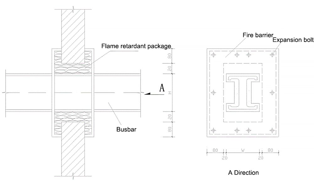
Connections of enclosed and plug-in busbars should avoid busbar brackets, and busbar connections should not be made where they pass through floors or walls. When the busbar passes through the fire wall and fireproof floor, fire isolation measures should be taken. As shown in Figure 8.
Figure 8: Fireproofing Method for Wall Penetration of Enclosed Busbar
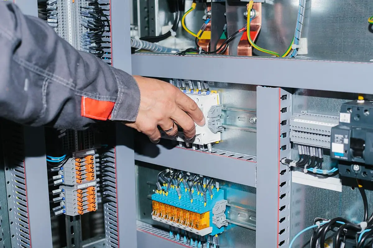
The plug-in distribution box should match the busbar slot with plug-in holes. During the installation of the enclosed plug-in busbar, the distribution box should be placed in a safe, convenient for operation and maintenance location, and it is advisable for the bottom edge of the distribution box to be 1.4-1.6m above the ground.
For the connection between the enclosed, plug-in busbar and the low-voltage distribution screen, a starting line box (inlet protection box) should be used at the starting end of the busbar. The inlet box is connected to the distribution screen with a transition busbar, which is a copper row, and the busbar connections at both ends should be tin-plated.
For the connection between the enclosed, plug-in busbar and the equipment, a steel conduit should be laid openly from the busbar plug-in distribution box to the equipment junction box (box), and the two ends of the steel conduit should be threaded. On the inside and outside walls of the box (box), a nut and a mouth guard should be used to tighten the conduit and the box (box). From the equipment junction box (box) to the equipment electrical control box, ordinary plastic pipes or metal flex tubes can be used.
6 Grounding of Enclosed, Plug-in Busbar
The metal shell of the enclosed, plug-in busbar should only serve as a protective shell and should not be used as a protective ground wire (PE wire), but the shell must be grounded. Each section of the busbar should be bridged with a braided soft copper strip of no less than 16mm, so that the busbar shells are interconnected.
7 Trial Run and Project Handover Acceptance
After the installation of the enclosed, plug-in busbar, it should be tidied and cleaned, the insulation resistance values between phases and relative to the ground should be tested using a megohmmeter, and records should be kept. The insulation resistance value of the busbar must be greater than 0.5 megohms.
If it meets the requirements after inspection and testing, it can run with no-load power for 24 hours without any abnormal phenomena, then the handover acceptance procedures can be carried out. If the enclosed, plug-in busbar cannot run with power temporarily after installation, a clear sign should be set up on site to prevent damage.
III. Quality Standards
1. Main control items
1) The base of the insulator, the flange of the bushing, the protective net (cover) and the busbar bracket and other exposed conductors should be grounded (PE) or zeroed (PEN) reliably. They should not be used as continuation conductors for grounding (PE) or zeroing (PEN).
Inspection method: Visual inspection.
2) The installation of the enclosed, plug-in busbar should comply with the following regulations:
1 The busbar and the shell should be concentric, with an allowable deviation of ±5mm.
2 When connecting section to section, the adjacent sections of busbar and shell should be aligned, and the connection should not cause extra stress to the busbar and shell.
3. The busbar connection method should comply with product technical document requirements.
Inspection method: Visual inspection and installation record review.
3) The low-voltage busbar handover test should comply with the following regulations: The insulation resistance values between the low-voltage busbar phases and relative to the ground should be greater than 0.5MΩ; the AC power frequency withstand test voltage is 1kV, when the insulation resistance value is greater than 20MΩ, a 2500V megohmmeter can be used instead for the test, which should last for 1 minute, with no breakdown or flashover.
Inspection method: Test record review.
2. General items
1) When the busbar bracket is welded to the embedded iron parts, the weld should be full; when fixed with expansion bolts, the selected bolts should be suitable and the connection should be firm.
Inspection method: Visual inspection.
2) The assembly and fixing position of the enclosed, plug-in busbar should be correct, the shell and the base, the shell and each connection part, and the busbar connection bolts should be selected correctly according to the product technical document requirements, and the connection should be firm.
Inspection method: Visual inspection.
IV. Finished Product Protection
1. The busbar should be properly packaged during transportation and storage to prevent erosion from corrosive gases and mechanical damage.
2. It is strictly forbidden to use the installed busbar to hang or support other items, and care must be taken to avoid collision with other objects and the insulating pillars of the busbar.
3. After the enclosed plug-in busbar is installed, if it cannot be powered temporarily, a conspicuous sign should be set up at the site to prevent damage. When other types of work are being carried out, the enclosed plug-in busbar should be protected to avoid damage.
4. When secondary spraying is performed in the transformer and distribution room, the busbar should be covered with plastic cloth.
5. The doors and windows at the busbar installation location should be installed and locked to prevent unauthorized personnel from entering.
V. Safety and Environmental Measures
1. The scaffold must be sturdy and reliable during busbar construction, and construction can only be carried out after passing inspection.
2. When the busbar is undergoing electric and gas welding operations, flammable materials around the area should be cleared, and firefighting facilities should be available.
3. After the busbar is powered, it should not be worked on or moved near to avoid electric shock accidents.
4. The busbar should not be put into operation before the project is handed over upon acceptance.
5. Before leaving work or at the end of work, the power supply should be cut off, and the operation site should be inspected. Only after safety is confirmed can one leave.
6. Materials such as paint used for busbar coloring should be managed by specialized personnel and strictly controlled. When used on-site, a dedicated person should supervise and be responsible for it. If there is any spillage, it should be immediately cleaned up and removed. Leftover paint should not be discarded at will, and a designated person should handle its recycling to avoid pollution to the land and water bodies.
7. Solid waste generated during busbar construction should be cleared after the work is completed, managed according to type, and uniformly recycled to designated locations for storage and transportation.
As the founder of MachineMFG, I have dedicated over a decade of my career to the metalworking industry. My extensive experience has allowed me to become an expert in the fields of sheet metal fabrication, machining, mechanical engineering, and machine tools for metals. I am constantly thinking, reading, and writing about these subjects, constantly striving to stay at the forefront of my field. Let my knowledge and expertise be an asset to your business.
Ever wonder what it takes to ensure a flawless busbar installation? This comprehensive guide will walk you through each step, from technical preparations to the final adjustments, ensuring your project…
Are you aware that improper installation of busbars can lead to costly and dangerous electrical failures? This article details the comprehensive standards for installing and inspecting busbars, including support brackets,…
Have you ever wondered how safety valves protect industrial equipment from catastrophic failures? Safety valves are vital for preventing explosions by releasing excess pressure from boilers and pressure vessels. This…
Currently, 3D printing technology is widely used in automotive manufacturing, aerospace and defense, consumer goods, electrical and electronic devices, biomedical applications, cultural and creative jewelry, construction engineering, and education, among…
Ever wondered how to pick the perfect motor for your project? The key lies in understanding the types of motors—DC, asynchronous, and synchronous—and their unique advantages. This article breaks down…
What if the crucial seal in your pump fails unexpectedly? Pump seals, while often overlooked, are vital to preventing leaks and ensuring smooth operation. This article dives into the different…
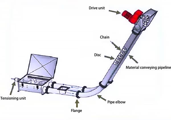
When it comes to efficient material transport in industrial settings, the choice between pneumatic conveying systems and pipe chain conveyors is crucial. Each has unique advantages: pneumatic systems are easy…
Have you ever wondered about the unsung heroes of industrial processes? In this blog post, we'll dive into the fascinating world of heat exchangers, the essential devices that quietly keep…
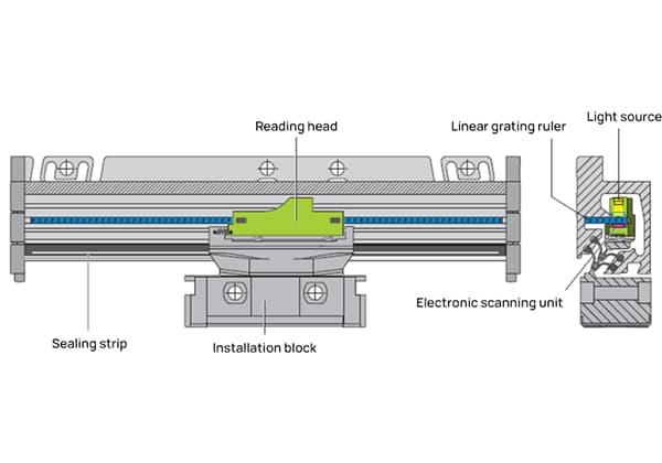
Imagine unlocking the precision of machine tools with a simple glass surface. Linear grating scales do just that, transforming fine lines into highly accurate measurements. This article explores how these…