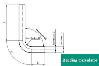
0° – 180° Bend Allowance Chart for Sheet Metal Bending
Have you ever wondered how sheet metal parts are designed and manufactured with precision? In this blog post, we'll dive into the fascinating world of bend allowance - a crucial…
Have you ever wondered about the art and science behind shaping metal sheets into complex forms? In this captivating blog post, we dive deep into the fascinating world of sheet metal bending. Our expert mechanical engineer unveils the secrets behind various bending techniques, materials, and equipment, offering valuable insights that will reshape your understanding of this crucial manufacturing process.
Sheet metal bending refers to the process of changing the angle of a sheet or panel, which can involve shaping it into various forms such as V or U shapes.
Related reading: V & U-shaped Bend Force Calculator
Generally, there are two methods used for sheet metal bending: mold bending and press brake bending. Mold bending is suitable for sheet metal parts with complex structures, low production volumes, and high-volume processing. Conversely, press brake bending is ideal for sheet metal structures with larger sizes or lower yields.
Both of these bending methods have their own distinct principles, characteristics, and areas of application.
Sheet metal bending is a process used extensively in the manufacturing industry. The material choice greatly affects the final product. This section will discuss the most common metals used for sheet metal bending, including their properties and applications.
Steel is a widely used and versatile material, consisting of iron and carbon. It exhibits desirable properties such as strength, durability, and cost-effectiveness. There are several types of steel available for sheet metal bending, including:
Aluminum is a lightweight, corrosion-resistant metal that offers excellent formability and electrical conductivity. Its advantages include:
Common applications include aerospace components, transportation equipment, and electronic enclosures.
Copper is a highly conductive metal that is easily bent and formed, making it the perfect choice for electrical and electronic applications. The key features of copper include:
Copper is used extensively in the electrical industry for wiring, circuit boards, and transformers, as well as in plumbing and decorative applications.
Brass, an alloy of copper and zinc, is a popular choice for sheet metal bending due to its ease of fabrication and attractive appearance. It offers various benefits, including:
Brass is commonly used in decorative and architectural components, musical instruments, and hardware fittings.
Air bending is a widely used technique in sheet metal processing. The process involves placing the sheet metal on a die with a V-shaped opening. The punch then applies pressure on the material, causing it to bend. The final bend angle depends on the depth of the punch penetration and the material’s characteristics. The advantages of air bending include:
Coining is a technique that uses significant force to force a sheet metal into a die, creating a bend. During the coining process, the punch and die are pressed together with the metal sheet sandwiched between them, causing the material to conform precisely to the shape of the die. The benefits of coining are:
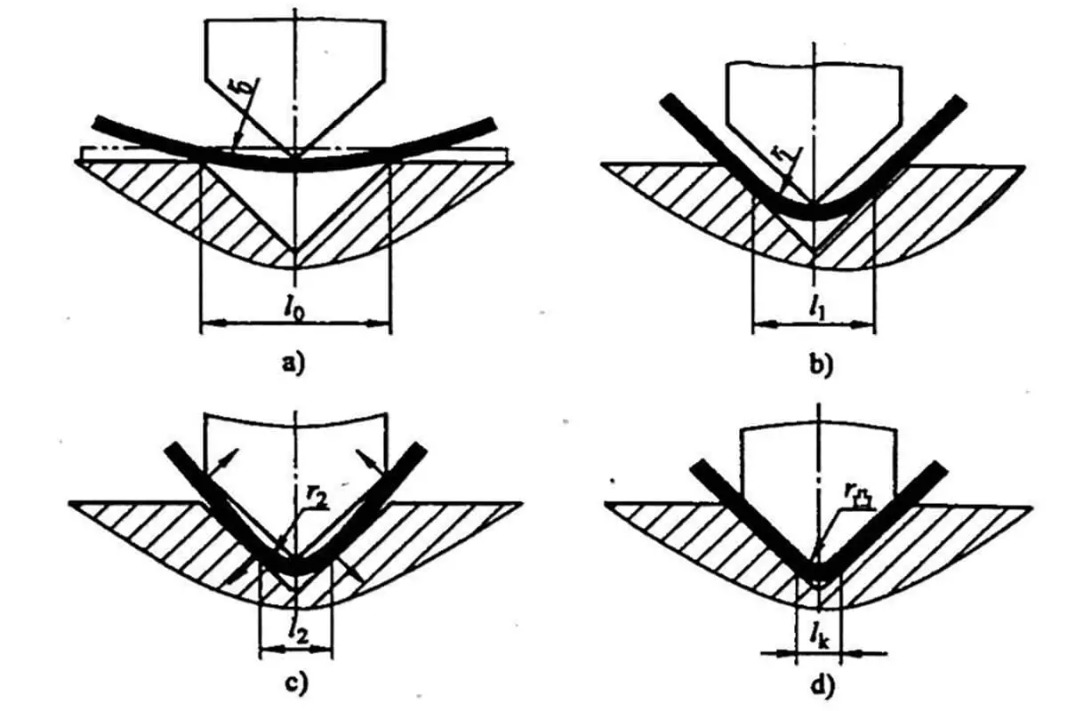
Three-point bending is a versatile technique used to determine the flexural properties of sheet metal. In this method, the metal sheet is supported at two points, with a force applied at a third point between the supports. This approach allows for:
V-die bending is a common technique in the sheet metal industry. The metal is placed between a V-shaped punch and die, which apply pressure to form the desired bend angle. This method offers:
Press brake is a widely used sheet metal bending equipment, offering high precision and accuracy in producing desired shapes. It consists of a punch and a die, which apply force on the metal sheet to produce the bend. Press brakes come in various styles, such as hydraulic, mechanical, and electric, to cater to different needs and requirements. The capacity of a press brake is determined by factors like the working length, tonnage, and type of control system.
Folding machines, also known as folders or bending brakes, are another essential equipment in sheet metal bending. They clamp the metal sheet between an upper and lower beam, followed by folding it to the desired angle using a folding blade. This equipment is suitable for various materials, like aluminum, stainless steel, and mild steel, and provides an efficient way of producing large volumes of bent parts. Folding machines can operate in manual or automated modes, depending on the complexity of the job.
Bending dies are crucial components of sheet metal bending equipment, as they determine the shape, angle, and radius of the finished bend. They are available in a range of materials, such as hardened steel, stainless steel, and tungsten carbide, to withstand the forces and friction involved in the bending process. Bending dies come in various types, including V-dies, rotary bending dies, and wiping dies, each with its unique characteristics and applications.
Sheet metal bending operations must adhere to specific international standards to ensure quality, safety, and consistency. The International Organization for Standardization (ISO) develops and maintains these regulations. For sheet metal bending, the relevant standards include:
Adherence to ISO standards ensures that sheet metal bending operations produce reliable, high-quality products for various industries and applications.
The American Society for Testing and Materials (ASTM) also plays a crucial role in the sheet metal bending industry by establishing and maintaining standards. ASTM standards relevant to sheet metal bending include:
Complying with ASTM standards ensures that sheet metal bending operations meet industry requirements and maintain a high level of quality in their products.
Manufacturers typically consider using mold bending as a processing method for structural parts that have an annual capacity of more than 5,000 pieces and are relatively small in size, generally around 300 x 300.
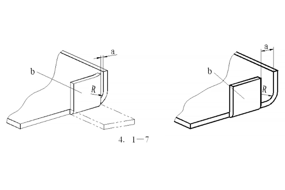
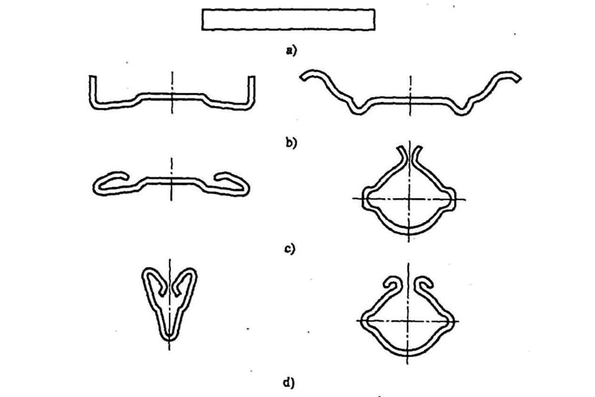
Figure 1-17 displays the commonly used bending dies. To increase the longevity of the mold, it is advisable to incorporate rounded corners while designing the parts.
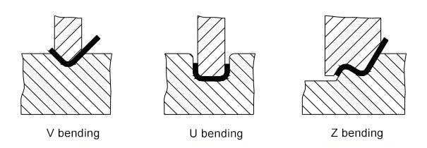
Figure 1-17 Special Forming Mold
Using a bending die with a flange height that is too small is not ideal for forming. Typically, the flange height should be L ≥ 3t, considering the wall thickness.
Z-shaped steps made from sheet metal with a lower profile are commonly bent using simple molds on punch presses or hydraulic presses for small batch sizes. For larger batches, a step die on a bending machine can be utilized, but the height (H) should typically be between 0 and 1.0 times the wall thickness (t).
If the height is between 1.0 and 4.0 times the wall thickness, a mold form with an unloading structure may be necessary. The height can be adjusted by adding a spacer, but maintaining the length (L) and verticality of the vertical side may be challenging. If the height is greater, bending on a press brake machine should be considered.
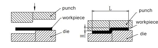
Figure 1-18 Z-shaped step bending
There are two categories of bending machines: ordinary bending machines and CNC bending machines. CNC bending machines are typically used for sheet metal bending in communication devices due to the need for high precision and the irregular shape of the bend.
The basic principle of the machine involves shaping the sheet metal part using the upper mold, which is the bending punch, and the lower mold, which is the V-shaped die.
Advantages:
Disadvantages:
The basic principle of forming is shown in Figure 1-19:
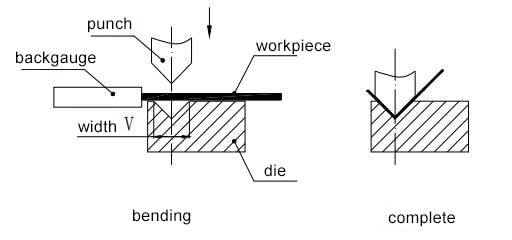
Figure 1-19 Basic principle of forming
The following are two key components of the bending machine:
1. Bending Knife (Upper Die)
The appearance of the bending knives is depicted in Figure 1-20. Their shape is mainly determined by the shape of the workpiece.
Typically, processing tools have a large selection of bending knives. Specialized manufacturers will even custom-make a variety of unique shapes and specifications to handle complex bending tasks.
2. Lower Die
The V-shape of the lower die is usually determined as V=6t (where t represents the material thickness).
The bending process is affected by various factors, such as the arc radius of the upper die, the material’s properties, its thickness, the strength of the lower die, and the size of the V-opening in the lower die.
To meet different product requirements, manufacturers have standardized bending dies while ensuring the bending machine’s safety.
Having a fundamental knowledge of the available bending dies is crucial during the structural design process.
Figure 1-20 displays the upper die on the left and the lower die on the right.
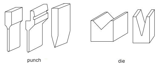
Figure 1-20 Schematic diagram of the press brake punch and die
The basic principle of the bending process sequence:
The bending forms commonly seen in outsourcing factories are generally shown in Figure 1-21.
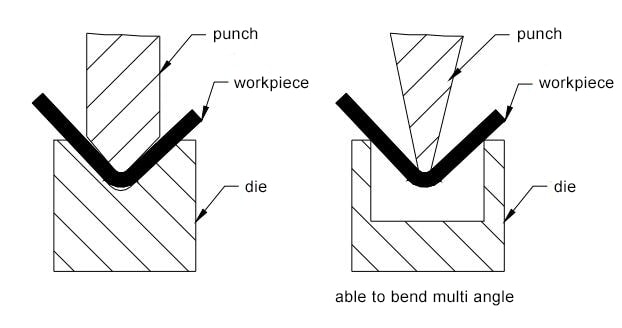
Figure 1-21 Bending form of press brake machine
The bend radius is a critical factor to consider when bending sheet metal. It is essential to choose an appropriate bend radius that is neither too large nor too small.
If the bend radius is too small, it can result in cracking during bending, and if it is too large, rebounding is likely to occur. Table 1-9 displays the preferred bend radius (inside bend radius) for different materials with varying thicknesses.
| Material | Annealed state | Cold work hardening state | ||
|---|---|---|---|---|
| The corresponding position of the direction of the bending line and the direction of the fiber | ||||
| vertical | parallel | vertical | parallel | |
| 08,10 | 0.1t | 0.4 t | 0.4 t | 0.8 t |
| 15,20 | 0.1 t | 0.5 t | 0.5 t | 1.0 t |
| 25,30 | 0.2 t | 0.6 t | 0.6 t | 1.2 t |
| 45,50 | 0.5 t | 1.0 t | 1.0 t | 1.7 t |
| 65Mn | 1.0 t | 2.0 t | 2.0 t | 3.0 t |
| Aluminum | 0.1 t | 0.35 t | 0.5 t | 1.0 t |
| Copper | 0.1 t | 0.35 t | 1.0 t | 2.0 t |
| Soft brass | 0.1 t | 0.35 t | 0.35 t | 0.8 t |
| Semi-hard brass | 0.1 t | 0.35 t | 0.5 t | 1.2 t |
| Phosphor bronze | —— | —— | 1.0 t | 3.0 t |
Note: t is the thickness of the sheet in the table.
Please note that the data presented in Table 1-9 is provided for reference purposes only and should not be considered as definitive. In actual practice, most manufacturers use bending knives with a rounded corner of 0.3, with only a few employing a rounded corner of 0.5.
Therefore, the bending inner radius of our sheet metal parts is typically 0.2. While this radius is sufficient for ordinary low-carbon steel plates, rust-proof aluminum plates, brass plates, and copper plates, it may not be suitable for high-carbon steel, hard aluminum, and super-hard aluminum. In these cases, a rounded corner of 0.2 may cause the bend to break or the outer corner to crack.
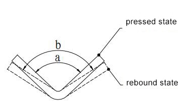
Figure 1-22 Bending and rebounding diagram
1) Rebound angle Δα=b-a
In the formula:
2) The size of the rebound angle
The rebound angle at 90° air bend is shown in Table 1-10.
Table 1-10 Rebound angle at 90-degree air bend
| Material | r/t | Thickness t(mm) | ||
|---|---|---|---|---|
| <0.8 | 0.8~2 | >2 | ||
| Low-carbon steel | <1 | 4° | 2° | 0° |
| Brass σb=350MPa | 1~5 | 5° | 3° | 1° |
| Aluminum, zinc | >5 | 6° | 4° | 2° |
| Medium carbon steel σb=400-500MPa | <1 | 5° | 2° | 0° |
| Hard yellow copper σb=350-400MPa | 1~5 | 6° | 3° | 1° |
| Hard bronze σb=350-400MPa | >5 | 8° | 5° | 3° |
| High carbon steel σb>550Mpa | <1 | 7° | 4° | 2° |
| 1~5 | 9° | 5° | 3° | |
| >5 | 12° | 7° | 6° | |
The magnitude of the rebound angle is directly proportional to the yield point of the material and inversely proportional to its elastic modulus, E. Therefore, when dealing with sheet metal parts that require high precision, it is advisable to use low-carbon steel instead of high-carbon steel or stainless steel to reduce rebound.
It is crucial to comprehend that the degree of deformation decreases as the relative bending radius, r/t, increases. Conversely, the rebound angle, Δα, increases as the relative bending radius, r/t, decreases.
To achieve higher accuracy, it is recommended to opt for a small bend radius while designing rounded corners of sheet metal bends. Avoid using large arcs as much as possible, as depicted in Figure 1-23, as they are difficult to produce and control for quality.
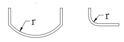
Figure 1-23 The arc of the sheet metal is too large
The initial state of the bend of the L-shaped bend is shown in Figure 1-24:
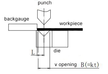
Figure 1-24 L-bend bending
One crucial factor here is the width “B” of the lower mold.
The bending process and the strength of the mold require a minimum mold width for different material thicknesses. If the width is less than this value, problems such as misaligned bends or damaged molds may arise.
Practical experience has shown that the relationship between the minimum mold width and material thickness can be expressed by the following equation:
Bmin = kT ①
Where Bmin is the minimum mold width, T is the material thickness, and k = 6 when calculating the minimum mold width.
The commonly used mold width specifications by manufacturers currently are:
4, 5, 6, 8, 10, 12, 14, 16, 18, 20, 25
Based on the above relationship, the minimum mold width required for different material thicknesses during bending can be determined. For example, when bending a 1.5mm thick plate, B = 6 * 1.5 = 9. From the above series of mold widths, you can choose either a 10mm or 8mm lower mold width.
From the initial bend state diagram, it’s clear that the bend’s edge cannot be too short. Combined with the minimum mold width, the equation for determining the shortest bend edge is:
Lmin = 1/2 (Bmin + Δ) + 0.5 ②
Where Lmin is the shortest bend edge, Bmin is the minimum mold width, and Δ is the sheet’s bending coefficient.
When bending a 1.5mm thick plate, the shortest bend edge, Lmin = (8 + 2.5) / 2 + 0.5 = 5.75mm (including plate thickness).
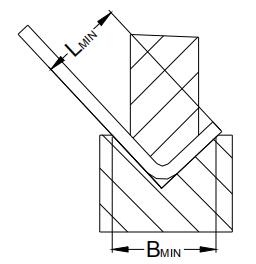
Figure 1-25 Minimum die width
Table 1-11: Inner bending radius of cold rolled steel sheet material R and minimum bending height reference table
| No. | Thickness | V opening | Punch radius R | Min bending height |
|---|---|---|---|---|
| 1 | 0.5 | 4 | 0.2 | 3 |
| 2 | 0.6 | 4 | 0.2 | 3.2 |
| 3 | 0.8 | 5 | 0.8 or 0.2 | 3.7 |
| 4 | 1 | 6 | 1 or 0.2 | 4.4 |
| 5 | 1.2 | 8(or 6) | 1 or 0.2 | 5.5(or 4.5) |
| 6 | 1.5 | 10(or 8) | 1 or 0.2 | 6.8(or 5.8) |
| 7 | 2 | 12 | 1.5 or 0.5 | 8.3 |
| 8 | 2.5 | 16(or 14) | 1.5 or 0.5 | 10.7(or 9.7) |
| 9 | 3 | 18 | 2 or 0.5 | 12.1 |
| 10 | 3.5 | 20 | 2 | 13.5 |
| 11 | 4 | 25 | 3 | 16.5 |
Note:
The minimum bend height is determined by the material thickness.
For acute V-bends, the shortest bend must be increased by 0.5.
When bending aluminum or stainless steel plates, the minimum bending height may vary slightly. Specifically, the aluminum plate will require a smaller bending height, while the stainless steel plate will require a larger one. Please refer to the table above for details.
Figure 1-26 displays the initial state of the Z-bend. The Z-bend and L-bend processes share a similarity and encounter the minimum bend edge issue. However, the shortest edge of the Z-bend is larger than that of the L-bend, owing to the structure of the lower die. The formula used to calculate the minimum edge of the Z-bend is:
Lmin=1/2(Bmin+Δ)+D + 0.5 + T ③
Lmin refers to the shortest bend edge, while Bmin is the minimum mold width. Δ represents the bending coefficient of the sheet, T refers to the material thickness, and D is the structural size of the lower die to the edge, which is typically greater than 5mm.
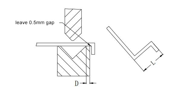
Figure 1-26 Z-bend
The minimum bend size L for sheet metal Z-bends of different material thicknesses is shown in Table 1-12 below:
Table 1-12 Minimum height of Z bend
| No | Thickness | V opening | Punch radius R | Z -bend height L |
|---|---|---|---|---|
| 1 | 0.5 | 4 | 0.2 | 8.5 |
| 2 | 0.6 | 4 | 0.2 | 8.8 |
| 3 | 0.8 | 5 | 0.8 or 0.2 | 9.5 |
| 4 | 1 | 6 | 1 or 0.2 | 10.4 |
| 5 | 1.2 | 8(or 6) | 1 or 0.2 | 11.7(or 10.7) |
| 6 | 1.5 | 10(or 8) | 1 or 0.2 | 13.3(or 12.3) |
| 7 | 2 | 12 | 1.5 or 0.5 | 14.3 |
| 8 | 2.5 | 16(or 14) | 1.5 or 0.5 | 18.2(or 17.2) |
| 9 | 3 | 18 | 2 or 0.5 | 20.1 |
| 10 | 3.5 | 20 | 2 | 22 |
| 11 | 4 | 25 | 3 | 25.5 |
Interference during bending
In the case of secondary or higher order bending, interference between the workpiece and the tool is a common occurrence. Figure 1-27 depicts the interfering area, shown in black, which can prevent successful bending or cause deformation due to the interference.
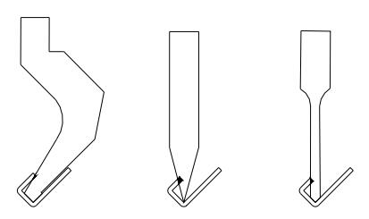
Figure 1-27 Interference of bending
The interference issue in sheet metal bending is not complex. It simply involves understanding the shape and size of the bending die and avoiding it when designing the structure. Figure 1-28 displays the cross-sectional shapes of several typical bending dies, which are detailed in the sheet metal mold manual and have corresponding tool entities in the intralink library.
If there is uncertainty in the design, a direct assembly interference test can be performed using the tool based on the principle shown in the figure.
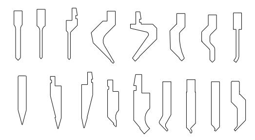
Figure 1-28 Bending knife
When performing flip hole tapping, it is important to avoid designing D (as shown in Figure 1-29) too small. The minimum value of D can be calculated or plotted based on various factors, including material thickness, outer diameter of the through hole, height of the flange hole, and selected parameters of the bending tool.
For instance, if you are performing M4 flip hole tapping on a 1.5mm sheet, D should be greater than 8mm to prevent the bending tool from coming into contact with the flange.
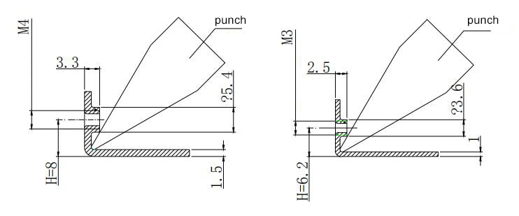
Figure 1-29 Bending of the hole flanging & tapping
Figure 1-30 illustrates that if the hole’s edge is positioned too close to the bending line, the bending process may cause the hole’s shape to change, as it cannot be accommodated. To prevent this from happening, it is crucial to ensure that the distance between the hole’s edge and the bending line is greater than or equal to the minimum hole margin, which is X ≥ t + R.
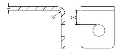
Figure 1-30 Minimum distance from the round hole to the bent edge
Table 1-13 Minimum distance from the round hole to the bent edge
| Thickness | 0.6~0.8 | 1 | 1.2 | 1.5 | 2 | 2.5 |
|---|---|---|---|---|---|---|
| Min Distance X | 1.3 | 1.5 | 1.7 | 2 | 3 | 3.5 |
Figure 1-31 reveals that the elongated hole is located too near the fold line. Consequently, during the bending process, the material cannot be properly accommodated, resulting in deformation in the hole’s shape. Therefore, it is crucial to ensure that the distance between the hole edge and the bend line is greater than the minimum hole margin specified in Table 1-14. Additionally, the bend radius can be found in Table 1-9.
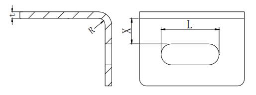
Figure 1-31 The minimum distance from the long round hole to the bent edge
Table 1-14 Minimum distance from the long round hole to the bent edge
| L | <26 | 26~50 | >50 |
|---|---|---|---|
| Min distance X | 2t+R | 2.5t+R | 3t+R |
For unimportant holes, they can be expanded to the bend line, as illustrated in Figure 1-32. However, this has a drawback of affecting the appearance.
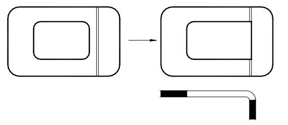
Figure 1-32 Improved bending design
If the distance between the closest hole to the bend line and the bent edge is less than the minimum required distance, deformation may occur after bending. To meet the product requirements, you can refer to Table 1-15 for potential solutions. Nonetheless, it’s crucial to note that these methods lack technical precision, and structural design should be avoided whenever feasible.
Table 1-15 Special processing when the hole is close to the bend
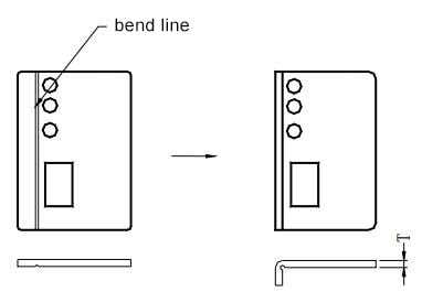 1) Press the groove before bending.In the actual design, because of the structural design needs, the actual distance is smaller than the above distance.The processing manufacturer often performs the groove pressing before the bending, as shown in Figure 1-31.The disadvantage is: one extra process is needed for the bending processing, the efficiency is lower, the precision is lower, and in principle, it should be avoided as much as possible. |
|---|
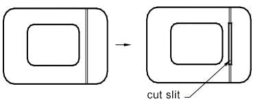 2) Cut hole or line along the bend line: when the bend line has no effect on the appearance of the workpiece or is acceptable, then use hole cutting to improve its techniques.Disadvantages: affect the appearance. And when cutting a line or cutting a narrow groove, it is generally necessary to cut with a laser machine. |
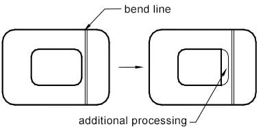 3) Completion to the design size after bending at the edge of the hole near the bend line.When the hole margin is required, it can be handled in this way.Generally, this secondary material removal cannot be completed on a punching machine, and the second cutting can only be performed on the laser cutting machine, and the positioning is troublesome, and the processing cost is high. |
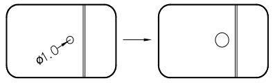 4) After the bending, the hole reaming process only has one or several pixel holes to the bending line and the distance is less than the minimum hole distance.When the appearance of the product is strict, in order to avoid the drawing during bending, the pixel can be performed at this time.Shrinkage treatment, that is, cutting a small concentric circle (usually Φ1.0) before bending, and reaming to the original size after bending.Disadvantages: many projects, low efficiency. |
 5) The minimum width of the upper die of the bending machine is 4.0mm (current).Due to this limitation, the hole in the bending part of the workpiece shall not be less than 4.0mm.Otherwise, the opening must be enlarged or use easy to form die to perform the bending.Disadvantages: low efficiency in making the easy mold, low efficiency in easy mold production; reaming affects appearance. |
Process holes, process slots and process notches for curved parts
When designing the bend, it is recommended to add a punching process hole, process groove, or process notch before blanking if the bend needs to be made on the inner side of the blank, as depicted in Figure 1-33.
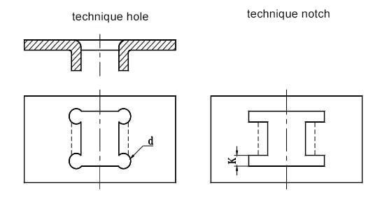
Figure 1-33 Adding punch hole, process or process notch
When designing a bent part, to prevent tearing and edge distortion, it’s typically necessary to create a crack avoidance groove or cut slit. This is especially important when the inner bend radius is less than 60 degrees. The width of the slit should be greater than the material thickness (t), and the depth of the slit should be at least 1.5 times the thickness of the material. As shown in Figure 1-34, Figure b is considered a better design option than Figure a.
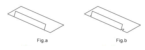
Figure 1-34 Bending of the sheet with the crack groove or slit
The process grooves and holes should be properly processed. If the appearance of the workpieces is a concern and they are visible from the panel, the corner process holes for bending can be omitted (for example, the process notch is not added during panel processing to maintain a uniform style). However, other bends should include a corner process hole, as shown in Figure 1-35.
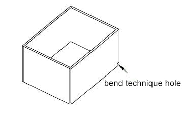
Figure 1-35 Bending corner process hole
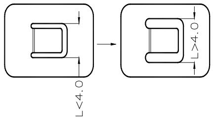
When designing drawings, it is recommended to avoid marking the gap between bending intersections in the 90-degree direction unless there is a specific requirement. Incorrect gap markings can impact the manufacturing process design. Usually, manufacturers design the process with a gap of 0.2 to 0.3, as illustrated in Figure 1-36.
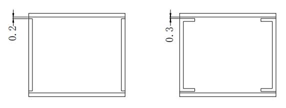
Figure 1-36 the gap between the bend lapping
The bending area of a bent component should be kept away from areas with abrupt changes in the component’s shape. The distance L from the bending line to the deformation zone should be greater than the bending radius (r), meaning L ≥ r, as shown in Figure 1-37.
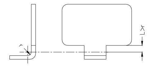
Figure 1-37 The bend zone should avoid the location of the sudden change of the part
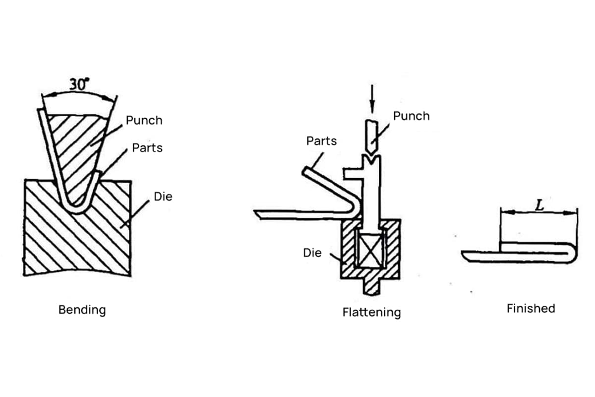
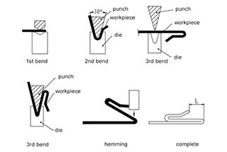
The method for hemming: The sheet is first bent to a 30-degree angle using a 30-degree bending die, as shown in Figure 1-38, and then the bent side is flattened.
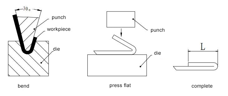
Figure 1-38 Method of hemming
The minimum bend edge dimension, “L,” in Figure 1-38 is 0.5t, where “t” represents the material thickness, in accordance with the minimum one-bend edge size outlined above. The “pressed dead edge” technique is commonly used for materials such as stainless steel, galvanized sheet, and aluminum-zinc plate. However, plating parts should not be used as it may result in acid entrapment at the hemming location.
The 180-Degree Bend Method: As shown in Figure 1-39, first fold the plate at a 30-degree angle using a 30-degree bending knife. Then, straighten the bend edge and finally, remove the backing pad.
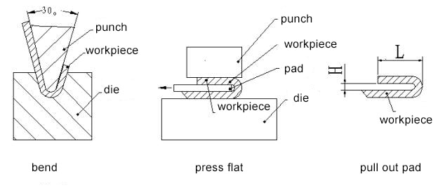
Figure 1-39 180-degree bend method
The minimum bend edge dimension (L) in the figure is equal to the minimum bend edge dimension of a single bend plus the material thickness (t). The height (H) should be selected from commonly used plate sizes, such as 0.5, 0.8, 1.0, 1.2, 1.5, or 2.0. It is generally not recommended to choose a height that is higher than these options.
As demonstrated in Figure 1-40, first fold the shape and then fold the edge. When designing, be mindful of the dimensions of each component to guarantee that each step of the process meets the minimum bend size, thereby avoiding the need for additional post-processing.
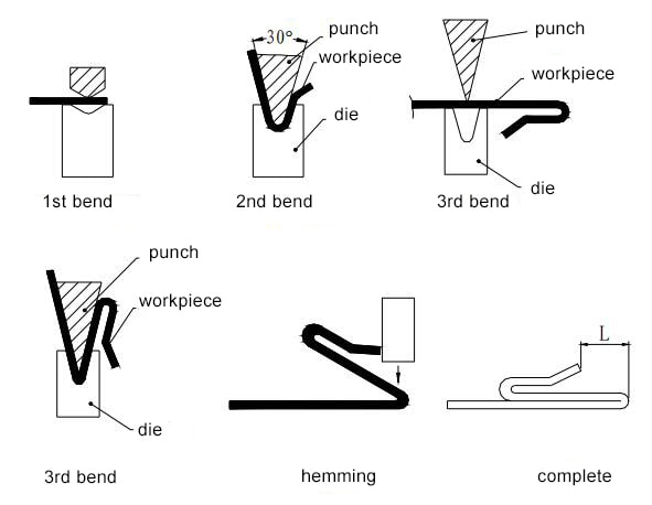
Figure 1-40 Triple folding hemming
Table 1-16 Minimum bearing edge size required for final bending edge flattening
| Thickness | 0.5 | 0.6 | 0.8 | 1.0 | 1.2 | 1.5 | 2.0 | 2.5 |
|---|---|---|---|---|---|---|---|---|
| Bearing edge size L | 4.0 | 4.0 | 4.0 | 4.0 | 4.5 | 4.5 | 5.0 | 5.0 |
When working with sheet metal bending, it’s crucial to prioritize safety and follow best practices to minimize the risk of accidents. Here are some key tips for ensuring a safe work environment:
Understanding the mechanical properties of the materials used in sheet metal bending is critical for both safety and success. Here are some best practices for working with various materials:
Additionally, a clean and organized workspace is vital for the safe and efficient execution of sheet metal bending tasks. By keeping the workplace tidy and in order, workers can easily locate their tools and reduce the risk of accidents due to tripping hazards or misplaced equipment.
By following these safety tips and best practices, operators can confidently conduct sheet metal bending operations in a professional and efficient manner without putting themselves or their coworkers at risk.

As the founder of MachineMFG, I have dedicated over a decade of my career to the metalworking industry. My extensive experience has allowed me to become an expert in the fields of sheet metal fabrication, machining, mechanical engineering, and machine tools for metals. I am constantly thinking, reading, and writing about these subjects, constantly striving to stay at the forefront of my field. Let my knowledge and expertise be an asset to your business.