Expert Busbar Installation Guide: Streamline Your Project
Ever wonder what it takes to ensure a flawless busbar installation? This comprehensive guide will walk you through each step, from technical preparations to the final adjustments, ensuring your project meets all quality and safety standards. Learn how to prepare resources, execute construction measures, and implement effective quality control. By the end of this article, you’ll be equipped with the knowledge to streamline your busbar installation process, ensuring both efficiency and reliability. Dive in to master the essentials of busbar setup and enhance your project’s success.
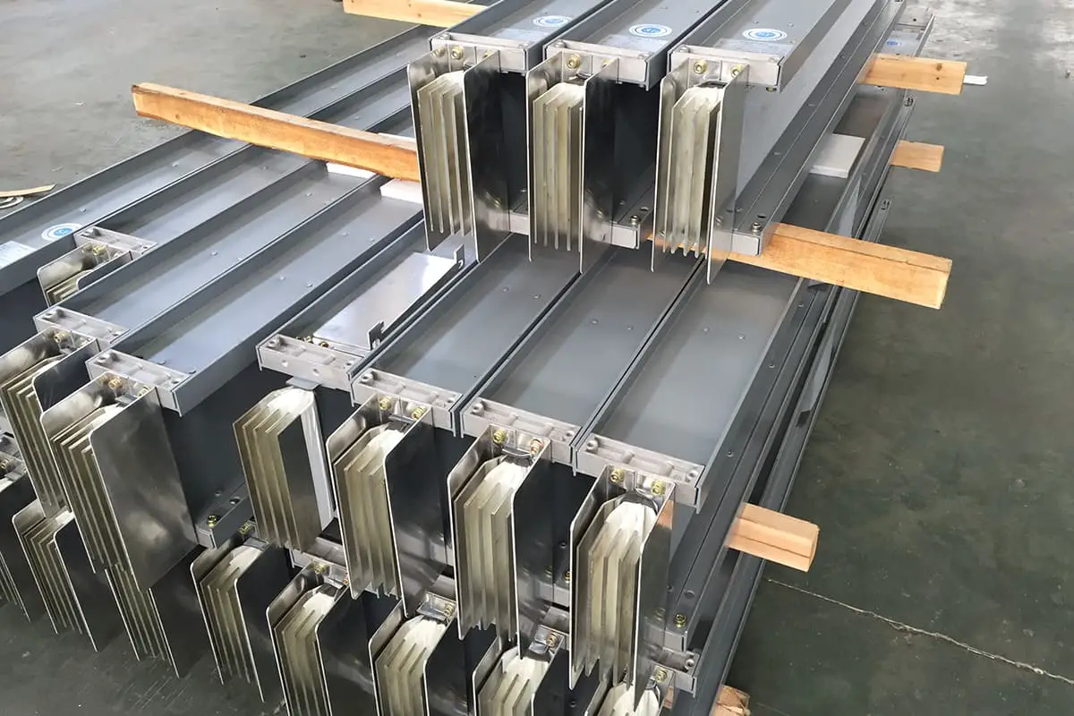
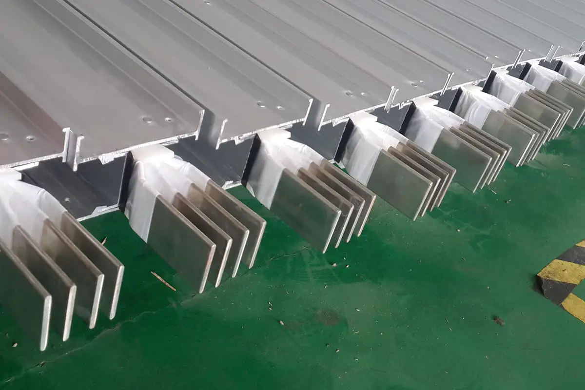
Installation of 220kV busbars, employing a dual busbar single-section connection, with an external suspension pipe busbar HGIS in a double-row arrangement.
Installation of 110kV busbars, utilizing a dual busbar connection, with an external suspension pipe busbar HGIS in a double-row layout.
Installation of the main transformer and the 10kV busbar bridge hard busbar. Installation of equipment connections and lead wires.
II. Construction Preparation
(1) Technical Preparation
The project team is organized to carefully study the drawings and conduct self-inspection and review work to ensure accurate and error-free construction. Through studying, familiarize with the content of the drawings, understand the technical standards to be achieved by the design requirements, and clarify the process flow.
Self-inspection is conducted, organizing the construction management personnel of each trade to review the relevant drawings of their own trades, familiarize with and master the details in the drawings. All professional construction teams are organized to study the construction drawings together.
A drawing review meeting is organized, with the design side conducting the briefing, understanding the design intention and construction quality standards, and accurately grasping the details in the design drawings. Ensure good technical briefing for construction, ensuring that each process is organized according to the specifications and technical measures.
Implement the quality inspection system rigorously, carry out quality and safety checks, and eliminate any potential quality and safety hazards.
(2) Resource Preparation Plan
1. Labor Preparation
No.
Job Type
Number of Personnel
1
Management Personnel
2
2
Electrician
2
3
Welder
2
4
High-altitude Worker
4
5
General Worker
10
Total
20
The personnel above can adjust according to the actual on-site conditions.
The above machinery and tools are adjusted according to the actual on-site conditions.
III. Busbar Construction Measures and Technical Requirements
(1) Soft busbar and its equipment wire clamp, hardware incoming goods inspection
1. Check the busbar nameplate, certificate of conformity, specifications, model according to the busbar equipment table, as well as the nameplate, certificate of conformity, specifications, model of the equipment wire clamp and hardware.
2. The busbar’s appearance should be smooth, without deformation, twisting, loose strands or obvious signs of corrosion.
3. The appearance of the equipment wire clamp and hardware should be smooth, without burrs, deformation, unevenness, sand holes, rust sliding buckles, and other defects.
4. The cutting of the fully supplied enclosed busbar and plug-in busbar slot should be clearly marked, with complete accessories, no deformation of the shell, and no internal damage. The bolt-fixed busbar overlap surface should be flat, and its galvanized finish should not be pitted, peeled, or uncovered.
5. The installation holes of various metal components should not be cut or blown by gas welding or electric welding.
(2) Busbar pitch measurement
1. The length error of the crossbeam should not be greater than 10-15mm, and the error of the distance between its hanging board and the A-shaped rod of the frame should not be greater than +30mm or less than -30mm.
2. The phase-to-phase error of the frame cross-beam hanging board should not exceed 10-15mm, and the three-phase distance should be consistent.
3. The bolt hole distance of the frame cross-beam hanging board should not exceed 3-5mm, and the hole distance direction and size should be consistent.
4. The pitch measurement should be carried out in windless or less than level 3 wind conditions, using a steel tape measure (greater than 50m) with good strength and flexibility. The measurement error should not exceed 5mm.
(3) Busbar Cutting and Crimping
1. During the busbar unwinding process, the wire should not rub against the ground or become twisted. A jack should be used to support the wire shaft. If the wire is twisted, broken, or noticeably loose, or if the damaged area at the same cross-section exceeds 5% of the conductive part, it should be replaced and not used.
2. Special tools should be used for wire cutting, and the cut end should be tightly bundled. The wire should not be tangled, damaged, or have a damaged steel core.
3. The wire crimping should use hydraulic or bolt connections, and explosive crimping should not be used.
4. The specifications and gaps of the soft busbar and the metal parts must match, and they should comply with the current national standards.
5. There should be no connecting joints within the pitch of the soft busbar and the combined wire, and a special wire clamp should be used for connection on the jumper.
6. When the soft busbar is led to the equipment by a bolt tension clamp, it should not be cut off and should become a single entity.
7. Before wire crimping, the oxide film on the contact surface of the wire and the wire clamp should be cleaned in advance, and the cleaning length should be 1.2 times the crimping part. The crimping length of the tension clamp or equipment wire clamp should reach the specified length.
8. The steel mold used for hydraulic pressure must match the pressed part. During crimping, the position and direction of the wires and wire clamps must be correct and not be pressed crookedly. Each mold crimping should overlap by 5-10mm, and burrs should be removed after crimping.
9. The hexagonal size across the corners after crimping should meet 0.866 times the outer diameter of the pipe. When it exceeds 0.866+0.2mm, the steel mold should be replaced promptly.
(4) Installation of Soft Busbars
1. The three-phase slackness of the busbars in the same pitch should be consistent during production. Similarly arranged branch lines or split conductors should also have the same curvature and slackness.
2. The slackness of the busbar should comply with the design drawings, and its error range is between +5% to -2.5%.
3. When installing the combination busbar, the fixed wire clamp, various fittings, and spacer rods must be complete, and the distance error on the conductor should not be greater than +3% to -3%. The installation should be firm.
4. When installing the combination busbar, the hanging porcelain bottle, U-ring, hanger connecting plate steel anchor, and fixed fittings should coordinate consistently, and the fixed reliable pin should be complete.
5. The appropriate suspension points should be selected when hoisting the conductor onto the crossbeam. Assemble the busbar connectors on the ground and lift them into position tied to the steel wire rope.
(5) Inspection of Pipe Busbars and Equipment Wire Clamps and Fittings
1. Verify the nameplate and certificate of the incoming pipe busbars, specifications, models, equipment wire clamps, fittings’ nameplate, certificate, specifications, and models.
2. The appearance of the pipe busbar should be smooth, free of deformation, and clear damage or corrosion.
3. The appearance of the equipment wire clamp and fittings should be smooth, free of burrs, deformation, unevenness, sand holes, rust sliding buckles, and other defects.
(6) Tubular Busbar Processing
1. Before cutting the tube, calculate the welding length of each aluminum tube based on the cross-sectional view of the entire busbar and the length of the delivered tube. Ensure that the location of the busbar butt weld is no less than 50mm away from the fixing fixture of the pillar insulator and should avoid the installation location of the jumper fixture between each gap. The cut surface of the tube should be flat and perpendicular to the axis. The lining tube should be cut according to the design drawings.
2. Use a beveling machine to pre-process the bevel of each tube joint. The bevel should be smooth, uniform, and burr-free. For instance, if the busbar thickness is 7mm, the processed product should meet the following standards: blunt edge thickness of 1.5mm, bevel angle of 60-70°. If the busbar thickness is 5mm, the processed product should meet the following standards: blunt edge thickness of 1mm, bevel angle of 60-65°.
3. Use a bench drill to process reinforcement holes at the joint of the tubular busbar according to the drawings. Finally, align each tube on the correction platform until it meets the specification requirements.
(7) Tube Busbar Welding
1. Due to the length of the tube busbar, a welding track must be set up at the welding site so that the tube can freely rotate and move laterally, facilitating the assembly of the welding operation machine. The welding guide rail is directly welded with five 6m [14] slot steels, and rollers are installed on the upper side of the slot steel slot (one pair every 1m). During the processing, it is necessary to ensure that the bending offset of the slot steel and roller centerline is ≦0.2%, the centerline offset is ≦0.5mm, and the horizontal error is ≦3mm. After the guide rail is processed, it should be placed according to the actual situation on site, ensuring good coordination with the main machine tools.
2. Before welding, the surfaces of both sides of the busbar groove within a range of 50mm should be brushed clean. The oil contamination within 50mm of the groove and the sides of the groove can be cleaned with a white cloth soaked in acetone. After drying, clean it with a clean stainless steel wire brush until the metal luster is revealed, and weld it promptly to avoid oxidation again.
3. Lift the aluminum tube to the welding guide rail, adjust the aluminum tube to make its butt joint straight, the bending offset is ≦0.2%, the centerline offset is ≦0.5mm, and the gap between the butt pipes is 1mm.
4. Tube busbar welding adopts argon arc welding. To prevent the strength of the tube busbar from decreasing after welding, measures to compensate the melting point of the liner tube are adopted. The longitudinal axis of the reinforcing liner should be in the center of the weld seam, and the gap between the liner and the tube busbar should be less than 0.5mm.
5. There are no special requirements for the tube busbar welding process. Windproof measures should be taken during the welding process.
6. During welding, first locate the reinforcement hole for welding, then weld the busbar and liner tube firmly at the groove. During the welding process, the welding gun should always maintain flat welding, and other personnel should slowly rotate the aluminum tube at both ends to ensure uniform thickness of the welding seam. The upper part of the busbar butt joint weld should have a reinforcement height of 2-4mm, the weld should be arc-shaped, all weld seams and weld points should be flat and smooth, and there should be no burrs, unevenness, and visible cracks, depressions, missing meat, incomplete welding, pores, slag, etc.
7. Each weld should be completed in one go, and welding must not be stopped except for instantaneous arc interruption. The tube busbar should not be moved or subjected to force before the weld is cooled. If the busbar needs to be turned over, force must be applied to both ends and the middle at the same time to avoid excessive force on the weld.
(8) Busbar Installation
1. Before installing the busbar, according to the busbar segment number, clarify which segment of the busbar corresponds to which length, and which phase it should be installed in to avoid installing in the wrong position.
2. Insert a damping wire into each busbar as per the design requirements. Install the end cap or end ball, paint it with phase color, and ensure that the water droplet hole of the end ball is facing downwards. Before installing the busbar, the hardware on the busbar should also be pre-installed for one-time installation.
3. As the busbar span is relatively large, to prevent the busbar from bending and deforming during installation, multiple points should be used for installation to improve precision. The strength safety factor of the sling should be no less than 5, the angle of the binding rope should not exceed 90°, and the binding points on the busbar should consider anti-skid and easy release.
4. When the busbar is 100mm off the ground, stop lifting, clean the busbar again, and drill a Φ6mm water droplet hole near the lowest point of each busbar segment (avoiding the welding part). Check the force situation of the sling and busbar. Continue lifting only after confirming that there are no conditions that would affect the lifting process.
5. During the lifting process, always pay attention to the level of the busbar. The two cranes should be under unified command and relatively balanced lifting (ensure that the busbar height difference is ≤500mm), so that each lifting point is basically evenly stressed. If there is unevenness, adjust it before continuing to install. Finally, lift it smoothly to the actual installation position and fix the busbar with the hardware on the supporting insulator.
(9) Busbar Adjustment
1. After the busbar is installed, check and adjust the level of the three phases and the error of the same distance. You can add or subtract shims at the bottom of the supporting insulator to ensure the horizontal and longitudinal level of the busbar, and keep the elevation of the busbar in line with the design requirements. The axis of the same phase segment is in a vertical plane, and the axis of the three-phase busbar segment is parallel to each other.
2. Adjust the fixed and movable busbar clamps according to the drawing requirements. Note that there should be a gap of 1-2mm between the axis seat of the movable type and the busbar. The distance between the expansion joint and the clamp should meet the design requirements to prevent the busbar from getting stuck due to thermal expansion and contraction.
(10) Installation of Equipment Drawdown Line
1. The crimping of the equipment drawdown line should meet the requirements of Article 3.3;
2. When the equipment drawdown line clip is connected to the equipment terminal board, the surface oxide layer should be removed, and conductive composite grease should be applied. The bolts should be tightened, exposing 2-3 threads.
IV. Quality Control Measures for Construction
1. Carry out construction strictly in accordance with the drawings, specifications for electrical device busbar construction, and job instruction manuals.
2. Quality inspectors should participate and conduct random inspections during the processing, crimping, and installation of flexible busbar and tubular busbar. For certain projects, supervision personnel should conduct random inspections.
3. Strictly control construction errors, check the quality of procedures in a timely manner, and rectify any problematic procedures to prevent them from entering the next procedure.
4. Strictly control the quality of busbar crimping and welding.
5. Keep a record of the construction process on time and fill out the installation records promptly.
V. Occupational Health, Safety, and Environmental Management Measures
(1) Safety Measures
1. Firmly implement the construction policy of “safety first, prevention-oriented, and comprehensive management”.
2. Construction personnel entering the site must absolutely obey the supervision of safety inspectors and construction managers. Strictly follow safety management rules and regulations and construction safety procedures, and conscientiously fulfill the safety duties of construction personnel at all levels.
3. Before construction, check the safety and reliability of construction tools. Construction personnel should wear safety-qualified construction protective equipment.
4. Carry out the technical disclosure work and the issuance of safety work order tickets.
5. Construction machinery should be guided by technical personnel on site to avoid blind and illegal operations.
6. Hydraulic workers and argon arc welding workers should be certified to work, to prevent illegal operations.
7. Special measures should be taken to protect the equipment when the busbar is hoisted in place.
8. Falling objects from high places and throwing things are strictly prohibited. Small ropes should be used for lifting.
9. High-altitude workers should wear safety belts, be dressed comfortably, wear soft-soled shoes, and pay attention to observing ground work conditions. Pass items using a tool bag to prevent throwing and falling objects from high places.
10. Carry out civilized construction, and ensure “all materials are used up after work, and the site is clean”.
(2) Sources of Danger and Pre-control of Dangerous Sources
1. The main dangers during construction are: high altitude work and mechanical construction.
2. Measures for pre-controlling the sources of danger:
2.1 A special guardian should be set up at the work site.
2.2 Climbing personnel must wear safety-qualified protective equipment, such as safety belts and foot buckles. Climbing personnel should carry nylon ropes for passing tools and prevent falling objects from high places. Before construction, carefully check the mechanical performance of the machinery (manual grinding), check whether the steel wire rope has broken strands, and whether the pulleys and buckles meet the tension requirements of the wires to be lifted.
2.3 Before construction, carefully check the condition of the machinery. Machines with problems are not allowed to enter the site for construction.
2.4 The safety responsibility is clear, and the safety briefing before work is in place, so that each construction personnel can truly understand the safety precautions that should be taken for each process, ensuring the safety protection function of the construction front line.
(3) Environmental and Occupational Health Measures
1. Establish an environmental protection responsibility system, strengthen publicity and educational work, and encourage workers to conscientiously implement environmental protection measures. During the construction process, prevent and minimize the impact on the construction site and surrounding environment.
2. Construction waste should be centrally managed (stored and treated), and should not be arbitrarily discarded, causing environmental pollution.
3. During and after the construction process of the project, the ecological environment that was damaged during the construction process should be timely repaired and restored, and greening measures should be adopted as much as possible.
4. The construction and domestic water of the construction project should be organized and treated rationally according to the separation of clean and polluted water.
VI. Standard Process Requirements
Standard Process Application List
Serial Number
Process Number
Process Name
Application Part
Process Standard
220kV Outdoor Distribution Equipment110kV Outdoor Distribution Equipment
1
010*******
Insulator String Assembly
Insulator String Assembly
(1) The insulator’s appearance and ceramic quality are intact, with no damage. The cast steel parts are in good condition, with no rust. (2) The connection hardware matches the conductor of the busbar in use. The hardware and fasteners are smooth, with no cracks, burrs, or unevenness. (3) The spring pin should have sufficient elasticity. The pin opening must not be less than 60°, and there must be no breaks or cracks. The use of wire as a substitute is strictly prohibited. (4) The adjustment nut of the adjustable hardware is tightly locked.
2
010*******
Installation of Pillar Insulators
Installation of Post Insulators
(1) The deviation in the bracket elevation should be ≤5mm, the deviation in verticality should be ≤5mm, and the deviation in the levelness of the top surface should be ≤2mm/m. (2) The exterior of the insulator pillar should be clean, without cracks, the base should be firmly fixed, and the force should be evenly distributed. (3) The vertical error should be ≤1.5mm/m, the base levelness error should be ≤2mm, and the error in the centerline of each insulator column within the straight section of the busbar should be ≤5mm. (4) The base should be firmly connected to the grounding grid, with good conductivity.
3
010*******
Installation of Busbar Grounding Switch
Installation of Busbar Grounding Switch
(1) The deviation of the bracket elevation should be ≤5mm, the verticality deviation ≤5mm, and the levelness deviation of the top surface ≤2mm/m. (2) The insulator column should be perpendicular (error ≤1.5mm/m) to the base plane and firmly connected. (3) The connection bolt between the insulator column and the operating axle of the base plane should be tightened. (4) The soft connection of the conductive part should be reliable and free of damage. (5) The terminal should be clean and flat and coated with power compound grease. (6) The operating mechanism should be firmly installed, the fixing bracket should be aesthetically pleasing, and the mechanism axle should coincide with the base axle, with a deviation of ≤1mm. (7) The cable arrangement should be neat and aesthetically pleasing, and the fixing and protection measures should be reliable. (8) The grounding of the equipment base and mechanism box should be firm and have good conductivity. (9) The operation should be flexible and the contact of the contactor should be reliable. (10) The grounding should be firm and reliable. (11) The installation of the equalizing ring should have no scratches or burrs and should be firmly installed, flat, and free of deformation. The equalizing ring should have a drainage hole at the lowest point. (12) The vertical connecting rod should be grounded with a soft copper wire (provided by the manufacturer) and should be marked in black.
4
010*******
Installation of Downlead and Jumper Wire
Arrangement of Cross-sections for Each Space and Main Busbar Flat Cross-section
(1) The positioning of the high-span line (T-shaped) clamp is reasonable, with the down line and jump line appearing natural and aesthetically pleasing, and the arc is appropriate. (2) The direction of the equipment line clamp (angle) is rational. (3) When installing the soft conductor wire clamp with the mouth facing upwards, a drainage hole with a diameter no larger than 8mm should be punched at the bottom of the clamp. (4) The bending degree of the aluminum pipe is less than 2%. (5) When crimping, the correct position of the wire clamp must be maintained, it must not tilt, the overlap between the two adjacent molds should not be less than 5mm, and the size of the hexagonal opposing sides after crimping should not be greater than 0.866D+0.2mm (D is the outer diameter of the connecting pipe).
5
010*******
Installation of Suspended Tubular Busbar
Main Busbar Flat Cross-Section Layout
(1) The busbar should be straight, with neat ends, and a deflection less than D/2 (D refers to the diameter of the tubular busbar). (2) The three phases should be parallel and equally spaced. (3) The jumper wires should be naturally oriented, and consistent across the three phases. (4) The hardware specifications should match the tubular busbar. (5) The installation of the pressure equalizing ring should not have scratches or burrs, and should be firmly installed, flat, without deformation. The pressure equalizing ring should have drainage holes at the lowest point.
Installation of Main Transformer and 10kV Busbar Bridge
6
010*******
Installation of the Main Transformer Grounding Lead Wire
Installation of Grounding Lead for Main Transformer
(1) When flat steel is used for the grounding lead, it should be galvanized for corrosion protection. (2) The grounding lead and the equipment body are bolted together with a tight overlap. (3) The grounding body connection is reliable and aesthetically pleasing. (4) The body and neutral point both require two grounding points, each connected to different main lines of the grounding network. The neutral busbar should be marked in light blue. (5) The part of the grounding lead above the ground should be marked with yellow and green grounding symbols, with consistent intervals and sequence, with the top one being yellow. The width of the grounding symbol should be 15~100mm. (6) The neutral point of the 110kV and above transformer, the grounding lead of the clamp, and the body are reliably insulated. (7) A reliable jumper should be made between the upper and lower flanges of the bell-shaped body shell. (8) Test grounding terminals should be set according to operational requirements.
7
010*******
Insulator String Assembly
Installation of Main TransformerAssembly of Insulator String
(1) The insulator’s appearance and porcelain quality are in perfect condition, the cast steel parts are intact, with no rust. (2) The connecting hardware matches the conductor of the busbar being used, and the hardware and fasteners are smooth, with no cracks, burrs, or unevenness. (3) The spring pin should have sufficient elasticity, the pin opening must not be less than 60°, and it must not have any breakages or cracks. Wire substitutes are strictly prohibited. (4) The adjusting nuts of the adjustable hardware are tightly locked.
8
010*******
Flexible Busbar Installation
Installation of Main TransformerInstallation of Main Transformer Lead Wires
(1) The wires should have no broken strands, looseness or damage, and the expanded wires should have no depressions or deformations. (2) The appearance of the insulator and its porcelain quality should be intact, with no damage, and the cast steel parts should be in good condition with no rust. (3) The connecting hardware should match the wires, and the hardware and fasteners should be clean without any cracks, burrs, or unevenness. (4) The drainage plate should not be deformed or damaged. (5) The adjustment nuts of the adjustable hardware on the insulator string should be tightly locked. (6) The sag of the busbar should meet the design requirements, with an allowable error of -2.5% to 5%, and the sag of the three-phase busbar within the same span should be consistent. (7) The specifications and dimensions of the line clamp should match the specifications and model of the wire. (8) During crimping, the correct position of the line clamp must be maintained, it should not be skewed, the overlap between the two adjacent molds should not be less than 5mm, and the size of the hexagonal opposite side after crimping should not be greater than 0.866D+0.2mm (D is the outer diameter of the connecting tube). (9) The bending degree of the expanded wire should not be less than 30 times the outer diameter of the wire. (10) The bending degree of the aluminum tube should be less than 2%. (11) The installation of the equalizing ring should not have scratches or burrs, it should be sturdily installed, flat, and not deformed: the equalizing ring should have a drainage hole at the lowest point.
9
010*******
Installation of Drop Lines and Jumpers
Installation of Main TransformerInstallation of Main Transformer Lead Wires
(1) The placement of the clamps on high crosslines (T-shaped) is reasonable, and the direction of the drop and jump lines are natural and aesthetically pleasing with an appropriate radius. (2) The direction of the equipment clamp (angle) is reasonable. (3) When installing a soft lead wire compression clamp with the opening facing up, a drainage hole with a diameter not exceeding 8mm should be made at the bottom of the clamp. (4) The bending degree of the aluminum tube is less than 2%. (5) During crimping, the correct position of the clamp must be maintained, and it must not be skewed. The overlap between two adjacent molds should not be less than 5mm, and the dimension of the hexagonal opposite sides after crimping should not be larger than 0.866D+0.2mm (D is the outer diameter of the connecting tube).
10
010*******
Rectangular Busbar Installation
Installation of Main Transformer Busbar BridgeInstallation of Rectangular Busbar
(1) The elevation deviation of the pillar insulator bracket should be ≤5mm, the verticality deviation should be ≤5mm, and the levelness deviation of the top surface should be ≤2mm/m. (2) Expansion measures should be taken between the bushing terminals of the main transformer. (3) Conductors and insulators should be neatly arranged with consistent phase-to-phase distances. The levelness deviation should be ≤5mm/m, and the height difference of the top surface should be ≤5mm. (4) The pillar insulators should be firmly fixed, and the tightness of the conductor fixings should be appropriate. Except for the tightly fixed ends, all others should be loosely fixed to allow natural expansion and contraction of the conductor. (5) The fabrication of the rigid busbar should be level and vertical. The bending of busbar joints should meet the specification requirements, and the number of joints should be minimized. (6) Support insulators should not be fixed at bends. The distance from the edge of the fixing point clamp to the bend should not exceed 0.25L.
This construction plan is a working document used in conjunction with construction regulations, standards, and operation instruction manuals during construction. During construction, this plan should be referenced. In case of special circumstances, adjustments can be made as appropriate.
As the founder of MachineMFG, I have dedicated over a decade of my career to the metalworking industry. My extensive experience has allowed me to become an expert in the fields of sheet metal fabrication, machining, mechanical engineering, and machine tools for metals. I am constantly thinking, reading, and writing about these subjects, constantly striving to stay at the forefront of my field. Let my knowledge and expertise be an asset to your business.
Ever wondered how busbars, the unsung heroes of electrical distribution, are processed and installed? This article delves into the intricate steps of busbar selection, preparation, and installation, ensuring efficient and…
Are you aware that improper installation of busbars can lead to costly and dangerous electrical failures? This article details the comprehensive standards for installing and inspecting busbars, including support brackets,…
How do you transform raw copper and aluminum into critical components for electrical systems? This article delves into the intricate processes behind busbar fabrication, detailing the techniques and tools necessary…
How can you ensure the safe and efficient installation of bus ducts in your facility? This guide covers everything from preparing materials and equipment to detailed steps for installing enclosed…
What makes busbars crucial in electrical systems? Busbars, key components in substations and distribution systems, efficiently transmit electrical energy. This article explores their function, various types like rectangular and tubular,…
Ever wondered how to choose the right copper busbar for your electrical systems? This article breaks down the essentials of copper busbar selection and fabrication, ensuring your electrical setups are…
Have you ever wondered which cable is better: copper or aluminum? This article dives into a detailed comparison of copper and aluminum cables, highlighting their advantages and disadvantages. From resistivity…
Why is the debate between aluminum alloy and copper conductors so critical in the electrical industry? As materials for conductors, both have unique benefits and drawbacks. This article explores the…
Ever wondered if aluminum bus bars can match the performance of copper while costing less? This article explores the key differences between aluminum and copper bus bars, comparing their conductivity,…