Busbar Processing & Installation: Your Ultimate Guide
Ever wondered how busbars, the unsung heroes of electrical distribution, are processed and installed? This article delves into the intricate steps of busbar selection, preparation, and installation, ensuring efficient and safe power distribution. You’ll discover the essential tools and techniques needed to handle these critical components, enhancing your understanding of their role in low and high-voltage systems. By the end, you’ll have a solid grasp of busbar processing intricacies, from material inspection to final installation, ensuring optimal performance and safety in electrical applications. Dive in to power up your knowledge!
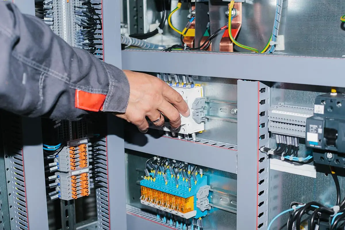
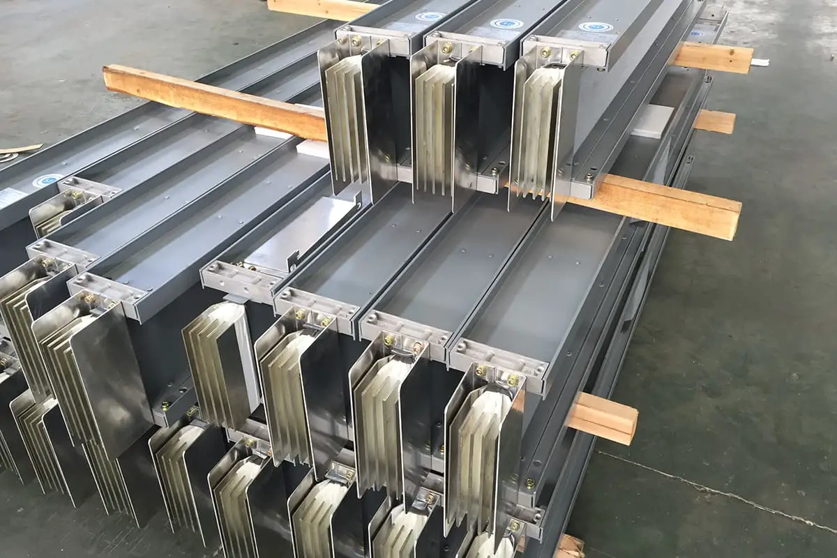
These guidelines apply to the busbar processing and installation of all low-voltage switchgear and power distribution boxes produced by our factory. Apart from the electrical clearance and creepage distance, other principles can also be used for high-voltage cabinets.
II. Selection of Busbars
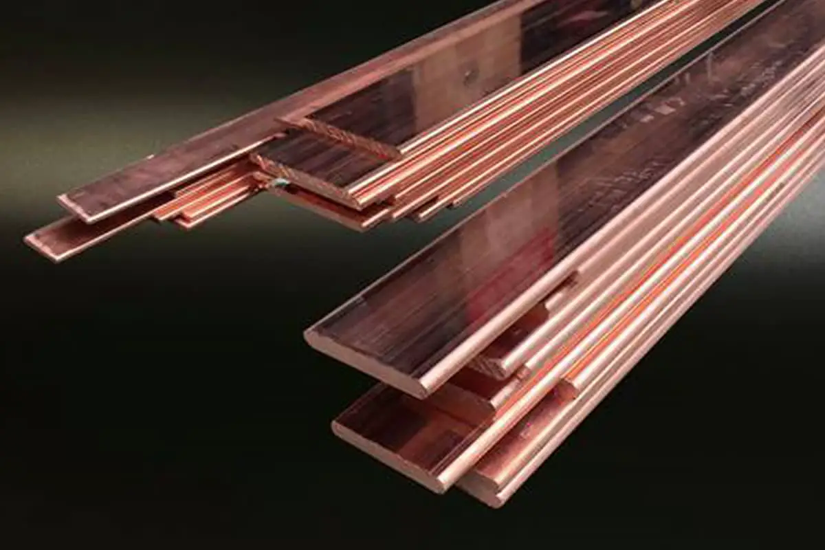
Busbars should be selected based on circuit current, under long-term permissible temperature rise conditions and dynamic thermal stability requirements. They should be either aluminum or copper busbars and copper core plastic wires.
The selected busbars must comply with the standards GB5584-85 “Aluminum Busbars” and GB55852-85 “Copper Busbars. Consideration should also be given to the impact of heat dissipation conditions on load capacity when vertically placed (good) versus horizontally placed (poor).
If the user has other requirements, the appropriate busbar should be selected according to those requirements.
1. Common busbar specifications and current carrying capacity are shown in Appendix A1
2. Copper core plastic wires are shown in Appendix A2
III. Materials, Equipment, and Tools
1. Various specifications of bolts, nuts, washers, and copper and aluminum joints
2. Bend row cutting machine, punch press, drill press and drill bits, manual bending machine, bench vise, socket wrench, strap wrench, spanner wrench, file, scriber, steel tape measure, square ruler, steel ruler, electrician knife, screwdriver, wire pliers, hand drill, etc.
IV. Processing Steps and Technical Requirements
1. Before processing the busbar material, it should be subjected to an external inspection. If surface cracks, blemishes, pits, or miscellaneous deposits are found, or if there are large pores on the surface (aluminum busbar diameter greater than 5mm, depth greater than 0.55mm, copper busbar diameter greater than 5mm, depth greater than 0.15mm), that section should be cut off.
2. The entire busbar should be basically straight before cutting. If there is obvious unevenness or straightness, it should be corrected.
3. Cut according to the drawing or template size (for example, cut on the cutting machine or punch press) and remove burrs during processing.
After cutting, if it is found to be uneven, not straight or twisted, it should be corrected with a wooden hammer or similar tool. After correction, there should be no obvious hammer marks on the busbar.
4. Bend the busbar according to its own requirements or the specific requirements of the switch cabinet. When the busbar is bent, care should be taken not to use too much force or speed to avoid cracking. The bending degree of the two parallel busbars of the same phase should be consistent.
(1) The minimum allowable radius for busbar bending is shown in Appendix A3.
(2) No cracks are allowed after the busbar is bent.
(3) The bending points of the same group of busbars should be basically consistent after installation.
(1) The pairing of the busbar hole and bolt specifications is selected according to Appendix A4.
(2) After determining the hole size according to the used busbar specifications, overlapping form, and electrical pile head form, drill or punch holes on a drilling machine or punch press.
(3) After the busbar is processed, cut-offs and hole edges should be deburred and chamfered.
6. Both the connection points between busbars and between busbars and electrical pile heads should be tinned and crimped, with neutral Vaseline applied to the tinned connection parts. Depending on the plant’s technical conditions, conductive paste can be used instead of tinning.
(1) For detailed busbar tinning procedures, refer to the “Tinning Process Guidelines”. For application of conductive paste, refer to the “Conductive Paste Application Guidelines”.
(2) Busbar crimping should be done using a dedicated crimping mold on a punch press.
(3) Before crimping, the crimping boundary should be marked (generally 20mm from the connection edge).
7. All busbars should be painted black. The painted edges should be basically on one line, without missing paint, drip marks, foreign objects, or other traces. The overlapping surface should not be painted, and the distance between the painted edge and the overlapping edge should be between 5-10mm.
V. Busbar with Copper-core Plastic Wires
Busbars with a rated current below 200A can be replaced with copper-core plastic wires, with copper/aluminum connectors crimped on both ends.
The stripping length and selected connectors are shown in Appendix A5. The exposed part of the crimping area should be wrapped with insulating tape.
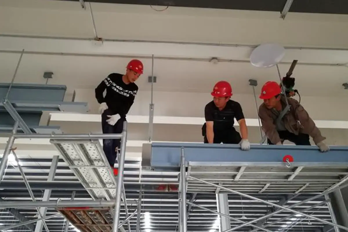
VI. Busbar Installation
1. Before installing the busbar, inspect the quality of the busbar and its accessories. Unqualified items are not allowed to be installed.
2. When the busbar is long (generally low voltage cabinet >0.8M, GCK >0.4M), a suitable busbar clamp and insulator should be used for fixing in the middle.
3. When the main busbar overlaps, the three phases must be staggered layer by layer and not crossed. When two or more busbars are used in parallel for the same phase, there should be a row’s thickness of space between the two (to increase the heat dissipation area).
4. During installation, the overlapping surfaces of the busbar to busbar and busbar to electrical pile head must be naturally flat. No external force should be used to press it flat, causing stress on the busbar, affecting the switch components, and the busbar’s dynamic thermal stability.
5. After tightening the bolts, there must be sufficient contact pressure between the overlapping surfaces. The contact tightness can be checked with a 0.05x10mm feeler gauge.
For busbars wider than 63mm, the depth of insertion in any direction should not exceed 6mm. For those less than 56mm, the depth of insertion should not exceed 4mm. The bolt head should protrude 2-5 threads from the nut (after tightening). It should not be too short or too long.
6. When the busbar is placed flat, the bolt should be inserted from top to bottom. When vertical, it should be inserted from front to back, that is, the nut should be placed on the back.
7. If there are difficulties in the contact area or layout, a transition bar connection can be added as needed.
8. The main busbar must be firmly clamped with a busbar clamp.
9. Except for special circumstances, busbars should be installed according to drawing requirements. Their layout and installation must ensure the electrical clearance (≥12mm) and creepage distance (≥14mm) between the busbar and other components and elements, auxiliary parts.
The minimum requirements for electrical clearance and creepage distance also meet the values specified in Table A8. It also meets the requirements for arc spraying distance (see “Electrical component, auxiliary installation, tuning process rules”).
10. For all horizontal busbars, vertical busbars, branch busbars, and live parts between main circuit connectors in drawer cabinets, and their electrical clearance and creepage distance from grounded metal parts, the rated voltage should be between 380V-660V and should not be less than 20mm.
Insulation wrapping, insulation sleeving, epoxy powder spraying or other insulation materials are allowed to be used as the insulating layer of the busbar to reduce the requirements for busbar clearance, but it should still meet the provisions of Table A8.
11. For other forms of low-voltage switchgear, the electrical clearance and creepage distance between main circuit busbars should also refer to the provisions of Article 10 when the dynamic thermal stability current passes through and may cause a reduction in electrical clearance.
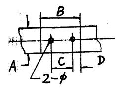
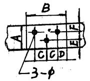
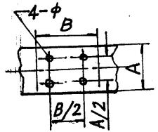
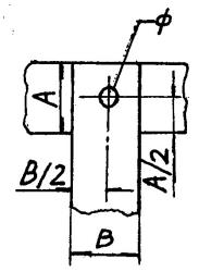
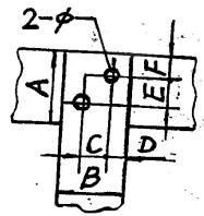
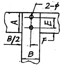
12. See Appendix A6 for the typical connection forms and requirements of busbar overlaps.
VII. Apply Sequence Markers
After the busbar is installed, phase sequence signs should be affixed in a prominent position on the busbar, or three-color paint blocks should be painted to indicate the phase sequence (Phase A: yellow; Phase B: green; Phase C: red).
(1) See Appendix A7 for the phase sequence arrangement of the busbar in the cabinet.
VIII. Quality Inspection
(1) Check whether there are cracks at the bend of the busbar and whether the surface is smooth.
(2) Check whether the tinning place of the busbar is smooth, bright, and uniform, and use a feeler gauge to check whether the gap between the busbar overlapping surfaces meets the requirements.
(3) Check whether the busbar is firmly installed and overlapped, whether the layout is beautiful, and whether it meets the requirements for electrical clearance, creepage distance, and arc spraying distance.
(4) Whether the phase sequence mark is correct.
Appendix A1 Single rectangular busbar specifications and current carrying capacity.
Copper Busbar TMY
Busbar Cross-Section(㎜2)
Maximum Permissible Current (A)
Horizontal Placement
Vertical Placement
Specification
Area
25℃
40℃
25℃
40℃
15×3
45
200
167
210
171
20×3
60
261
212
275
224
25×3
75
323
263
340
277
30×4
120
451
368
475
387
40×4
160
593
483
625
509
40×5
200
665
541
700
570
50×5
250
816
665
860
700
50×6
300
905
738
955
778
60×6
360
1069
893
1125
916
60×8
480
1251
1019
1320
1075
60×10
600
1395
1136
1475
1202
80×6
480
1360
1108
1480
1206
80×8
640
553
1265
1690
1377
80×10
800
17847
1423
1900
1548
100×6
600
1665
1356
1810
1475
100×8
800
1911
1557
2080
1695
100×10
1000
2121
1728
2310
1882
120×8
960
2210
1810
2400
1956
120×10
1200
2435
1984
2650
2159
Appendix A3: Minimum radius (R) for busbar bending (flat bend) (busbar thickness b)
MATERIAL/Specifications
TML
LMY
≤5×50
R=2b
R=2b
>5×50
R=2b
R=2.5b
Appendix A4: Busbar, Bolt Hole, and Diameter Fitting
Bolt Diameter
Busbar Hole
Bolt Diameter
Busbar Hole Diameter
M6
¢6.5
M12
¢13
M8
¢9
M16
¢18
M10
¢11
Appendix A5
Terminal (mm)
Wire Stripping Length (mm)
10
10
16
12
25
14
35
16
16
Note: Single-core wires less than 10mm can be installed directly using the bending circle method.
Appendix A7 Wire phase sequence arrangement
Arrangement Method/Phase Sequence
Vertical
Horizontal
Front and Back
Sign Color
A
Top
Left
Far
Yellow
B
Middle
Middle
Medium
Green
C
Bottom
Right
Near
Red
Neutral Line
Very Bottom
Finally
Closest
Note: The above is observed from the front of the cabinet. (Special cases may not follow this table, but must be marked)
Appendix A6 Dimensions of Bolt Connection Holes for Rectangular Busbars
As the founder of MachineMFG, I have dedicated over a decade of my career to the metalworking industry. My extensive experience has allowed me to become an expert in the fields of sheet metal fabrication, machining, mechanical engineering, and machine tools for metals. I am constantly thinking, reading, and writing about these subjects, constantly striving to stay at the forefront of my field. Let my knowledge and expertise be an asset to your business.
How do you transform raw copper and aluminum into critical components for electrical systems? This article delves into the intricate processes behind busbar fabrication, detailing the techniques and tools necessary…
Ever wonder what it takes to ensure a flawless busbar installation? This comprehensive guide will walk you through each step, from technical preparations to the final adjustments, ensuring your project…
Are you aware that improper installation of busbars can lead to costly and dangerous electrical failures? This article details the comprehensive standards for installing and inspecting busbars, including support brackets,…
Ever wondered how to choose the right copper busbar for your electrical systems? This article breaks down the essentials of copper busbar selection and fabrication, ensuring your electrical setups are…
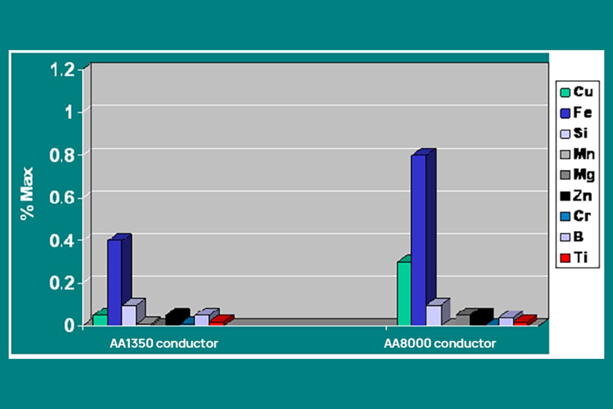
Why is the debate between aluminum alloy and copper conductors so critical in the electrical industry? As materials for conductors, both have unique benefits and drawbacks. This article explores the…
How can you ensure the safe and efficient installation of bus ducts in your facility? This guide covers everything from preparing materials and equipment to detailed steps for installing enclosed…