Have you ever wondered why some metal bends perfectly while others crack or warp? This article dives into the fascinating world of sheet metal bending, exploring the crucial factors that determine the optimum bending radius. You’ll learn how material thickness, bending force, and die selection impact the final bend, ensuring your metal projects are flawless.
The corresponding position of bending direction and fiber direction
Vertical
Parallel
Vertical
Parallel
08, 10
0.1t
0.4t
0.4t
0.8t
15, 20
0.1t
0.5t
0.5t
1.0t
25, 30
0.2t
0.6t
0.6t
1.2t
45, 50
0.5t
1.0t
1.0t
1.7t
65Mn
1.0t
2.0t
2.0t
3.0t
Aluminum
0.1t
0.35t
0.5t
1.0t
Brass
0.1t
0.35t
1.0t
2.0t
Soft Brass
0.1t
0.35t
0.35t
0.8t
Semi-rigid Brass
0.1t
0.35t
0.5t
1.2t
Phosphor bronze
/
/
1.0t
3.0t
The data in the table above is the preferred data for reference only. In fact, the rounded corners of press brake are usually 0.3, and a small number of the rounded corners of the press brake punch is 0.5.
For ordinary low carbon steel plate, anti-rust aluminum plate, yellow copper, purple copper etc, the inner radius 0.2 is no problem, but for some high carbon steel, hard aluminum, super-hard aluminum, the use of 0.2 radius will lead to bending fracture or the outer radius crack.
Factors That May Affect the Bending Radius
What are the factors that may affect the bending radius of the sheet metal?
There are several factors that can impact the bending radius of sheet metal, including the thickness of the metal, the material it is made of, the radius of the top punch, the bottom die, the bending force applied, and the working temperature.
I hope this article, based on my personal experience, will be helpful to readers.
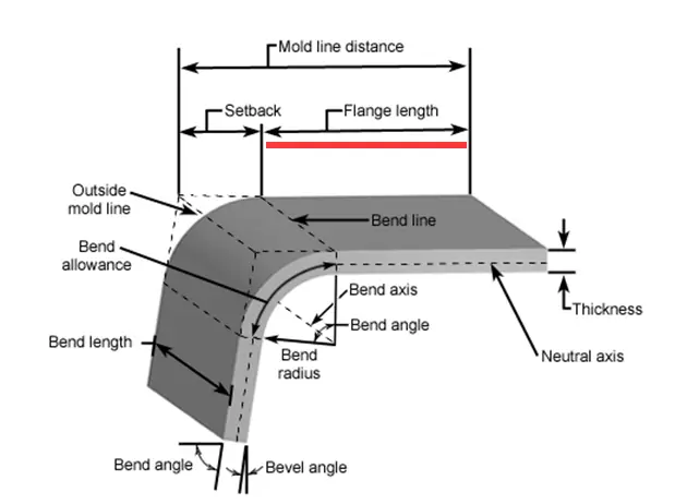
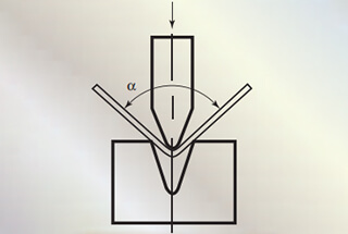
Bending Angle
The bending angle of the sheet metal is the key factor affecting the bending allowance.
For example, if bending the sheet metal with large radius, more bending allowance will be deducted; if bending acute angle, less bending allowance shall be deducted.
Sheet Metal Thickness
In practical applications, it has been observed that the bend radius increases as the material thickness increases.
We are aware that a thicker plate requires more bending force and a larger vee opening in the lower die.
What then affects the bend angle r?
Sheet Metal Material
The bending allowance for sheets of the same thickness can vary slightly, demonstrating that material properties play a role in determining the bending radius.
The material’s resistance to bending can directly influence the bending radius.
Although the material has an impact on the bending radius, it has limited effect on our actual usage.
We can create a custom bending allowance table for different materials.
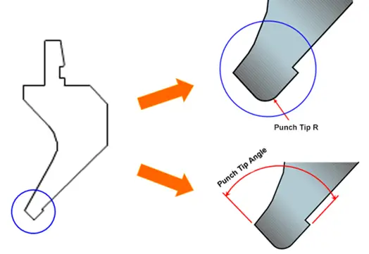
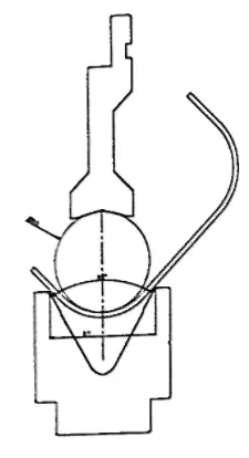
Punch Tip Radius
The standard bending mold radius must not exceed r1, and the minimum radius of the punch must be no less than 1.
If there are no specific requirements for the bending radius, it will have limited impact on the bending process.
However, for sheet metal bending that requires a specific bending radius that is either less than 1 or significantly larger than 1, it is not solely determined by the radius of the top punch.
Therefore, the radius of the top punch directly affects the final bending radius.
It is important to bear in mind that where the radius of the punch tip is greater than the radius generated by the vee die used in the bending, it will affect the internal radius of the profile.
For example:
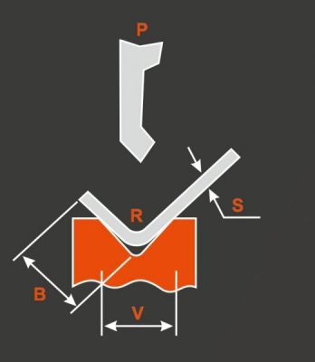
1 mm mild steel to be bent
Die chosen V = 8 mm, which, as shown below, produces a 1mm internal bending radius.
The internal bending radius will be:
r= 1 mm, where the punch tip radius is less than Imm
or r = punch tip radius where the punch tip radius is greater than 1mm.
A typical example of this principle is represented by radius tool holders that can be used to obtain large-radius bends in small dies. In this case, the required internal radius is produced by the shape of the punch tip.
Where instead you wish to retinthe internal bend radius produced by the die, the ideal punch tip rdius can be calculaled with the following equation:
Ideal punch tip radius = (R produced by the die) x (2/3)
Using this ratio the punch surface is proportional to the required force to bend the sheet metal prevening the punch tip from penetrating the sheet metal. This avoids aesthetic problems or cracks in the material on the inside of the bend.
In addition, with a tip radius that is too small and with acute angles it is possible for the metal sheet to be almost cut through and for the profile to close onto the punch thus producing an angle different from the one intended.
It is not always easy to comply with the above-mentioned equation due to a lack of different bending tip radi in many workshops.
However, press brake operators should use the tip radius closest to the ideal. Especially for thick sheet metal, which requires high force to be bent, operators must use appropriate punch tip radi to avoid sheet metal deformations, dimensional problems or problems involving appearance or cracking.
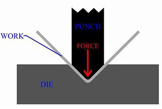
Bending Force
The thicker the sheet metal, the more resistance it has to bending deformation.
Therefore, the bending force must be adjusted accordingly.
The bending force cannot be constantly increased and must be set to an appropriate level.
The bending force is directly proportional to the thickness of the sheet metal and inversely proportional to the width of the lower die slot.
When bending, the thickness of the sheet metal is fixed and the width of the lower die slot is selected based on the thickness of the metal.
As a result, the bending force becomes a constant, determined by other factors.
The bending radius cannot be accurately determined without considering the bending force.
BottomDie
The width of the lower die slot has a direct correlation with the thickness of the sheet metal.
In real-world applications, the bend radius increases as the thickness of the metal increases.
For the same thickness of sheet metal, the bending radius can also vary depending on the width of the vee opening.
Therefore, it is clear that the width of the lower die slot plays a crucial role in determining the bending radius.
Operating Temperature
Generally, the working environment temperature is room temperature, which can be ignored.
Conclusion
The bending force contributes to changes in the bending radius, but it is determined by the thickness of the sheet metal and the width of the lower die slot.
All factors play a role in determining the bending radius, and they can only be limited based on specific requirements.
For example, if there are no specific requirements for the bend radius, limiting all factors and using a standardized bending factor table is appropriate.
If a much larger bend radius than 1 is desired, the radius of the upper die can be modified and a customized bending factor can be used.
However, it is not advisable to alter the width of the lower die slot, as it will have an impact on both the bending radius and the bending allowance.
Modifying the width of the lower die slot can be used to change the bending allowance and bending radius.
As the founder of MachineMFG, I have dedicated over a decade of my career to the metalworking industry. My extensive experience has allowed me to become an expert in the fields of sheet metal fabrication, machining, mechanical engineering, and machine tools for metals. I am constantly thinking, reading, and writing about these subjects, constantly striving to stay at the forefront of my field. Let my knowledge and expertise be an asset to your business.
Ever struggled to get perfect bends in sheet metal? This article dives into essential tips and tricks for mastering sheet metal bending, covering everything from process sequencing to analyzing bendability.…
Ever wondered how sheet metal is expertly bent into intricate shapes? This article explores six types of press brake bending processes—folding, wiping, air bending, bottoming, coining, and three-point bending. You'll…
Imagine turning raw materials into precise industrial components with just one step. This is the marvel of press brake die manufacturing. From mechanical extrusion to injection molding, the methods are…
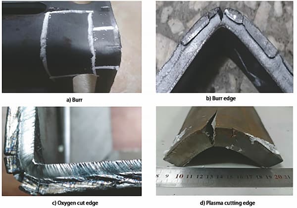
Ever wondered why steel sometimes cracks during bending? In this article, we explore the fascinating world of steel bending technology, uncovering the reasons behind common defects like corner and central…
Imagine buying a press brake and realizing it doesn't meet your needs—an expensive mistake! This guide explains the critical principles and factors to consider when purchasing a press brake. From…
Have you ever wondered what makes press brake dies so fascinating? In this captivating blog post, we'll delve into the intricate world of these essential tools that shape the metal…
Have you ever wondered how to precisely calculate the bending allowance for your metal fabrication projects? In this blog post, we'll explore the fascinating world of bend allowance formulas and…
Attention all mechanics and engineering enthusiasts! Have you ever wondered about the ins and outs of operating a press brake machine? In this blog post, we'll dive into the world…
Have you ever struggled with calculating the right bend allowance for your sheet metal projects? In this blog post, we'll dive into the world of bend allowances and explore how…