Minimize Welding Stress: Causes and Elimination
1. What is welding stress Welding stress refers to the stress generated during the welding process in welded components. This stress is caused by the thermal process of welding and [...]
Many devices nowadays pursue miniaturization and lightness, hence there’s often a demand for a tighter integration between motors and gearboxes. Sometimes, the motor is designed to be integral with a shaft in the gearbox.
For instance, the motor shaft serves directly as the high-speed shaft of the gearbox, connecting directly to the gear.
This design certainly reduces the size of the equipment and simplifies connections. If designed properly, it can also enhance reliability and reduce overall costs.
However, this integrated design presents new challenges to motor manufacturers in design, manufacturing, and installation. This article discusses the problems brought by gear motors to bearing selection and arrangement.
For convenience in discussion, we choose to talk about the helical gear motor with a relatively complex load situation.
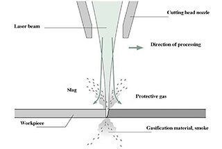
The following is a force diagram of a helical gear shaft system (the discussion below assumes that both sides are deep groove ball bearings; situations with other types of bearings require specific analysis following this thought process):

When designing motors, the tangential force of the rotor part is generally not included in the bearing load calculation. The primary reason for this is that the tangential force of the motor rotor is always counterbalanced by an equal but oppositely directed force, so this load is not transmitted to the bearing.
However, the situation is different for gearbox transmissions. For instance, in the figure above, the motor is directly connected to a helical gear. The gear transfers torque and endures unidirectional tangential force.
Without an opposing force to balance it out, this tangential force must be included in the bearing load calculation.
Therefore, in the figure above, the radial forces borne by the entire motor shaft system include:
Meanwhile, since the gear is a helical gear, the motor will endure the axial force, Fa, of the helical gear. Therefore, when verifying the lifespan of the shaft system bearings, all of the above loads need to be taken into consideration.
Let’s use the above illustration as an example. The image does not depict the markers for the positioning end and non-positioning end of the shaft system.
In previous articles, we’ve addressed that a motor shaft system needs to have one positioning end and one non-positioning end. So, let’s try to analyze the bearing arrangement of this helical gear shaft system.
Because the motor shaft is directly connected to the gear, the motor engineer must consider the meshing accuracy of the gear. If there’s a problem with the gear meshing, the consequences could be severe.
In the above example, the most direct factor affecting gear meshing accuracy is the axial and radial runout of the shaft.
The radial runout of the bearing can be roughly ensured through the radial clearance of the bearing.
However, the axial runout of the shaft requires considering the positioning relationship of the bearing system.
For instance, if the positioning end is placed at the rear bearing, as in the diagram, then when the motor runs from a cold state to a stable working temperature, the rotor temperature will rise.
The resulting thermal expansion will be transmitted from the floating end of the shaft outward. This transmission directly reaches the gear on the motor shaft end. The axial movement of the gear will inevitably affect meshing.
Therefore, from the perspective of gear meshing, the positioning end should be placed as close to the gear side as possible.
From a maintenance perspective, if the rear-end bearing is the floating end, then maintenance of the rear-end bearing and preloading spring can be conducted independently, without affecting the front-end bearing. Conversely, if arranged otherwise, the same maintenance would require disassembling the entire motor.
However, placing the positioning end closer to the gear side also brings additional impacts.
Firstly, the size of the bearing. In this structure, there is an apparent difference in the radial force distribution between the two bearings. The radial load borne by the left bearing is greater than that of the right bearing, hence the size selection of the left bearing will be larger.
Secondly, we know that the positioning end in a motor bearing bears the axial force. If we set the left side as the positioning end bearing, this bearing size will further increase under the condition of bearing axial force.
In reality, the shaft system design of a single motor requires a consideration to evenly distribute the load borne by the two bearings as much as possible.
However, in this application, due to the special requirements of the front-end gear, the motor engineer has to make a compromise.
The above only discusses one aspect of the gear motor bearing arrangement. In practice, such a design will bring other challenges, such as:
When using tapered roller bearings, additional knowledge in the field of gearbox bearing application technology, such as adjusting the bearing’s preloading, is required.
This poses yet another significant challenge for motor engineers. Motor engineers are advised not to blindly “copy” previous motor structures when designing such motor shaft systems to avoid unnecessary losses.

As the founder of MachineMFG, I have dedicated over a decade of my career to the metalworking industry. My extensive experience has allowed me to become an expert in the fields of sheet metal fabrication, machining, mechanical engineering, and machine tools for metals. I am constantly thinking, reading, and writing about these subjects, constantly striving to stay at the forefront of my field. Let my knowledge and expertise be an asset to your business.