What is plasma cutting?
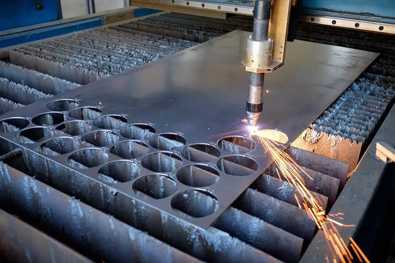
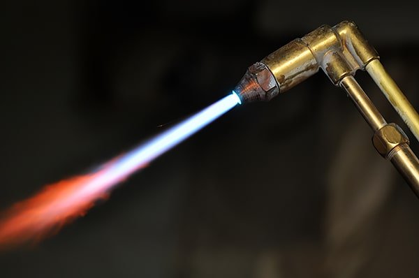
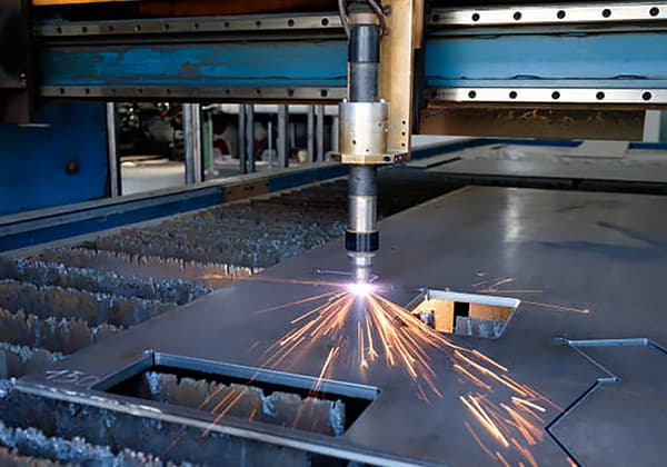
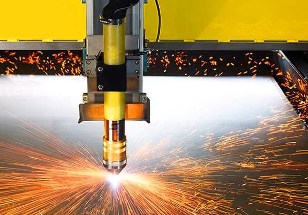
Plasma cutting is a method of processing that uses the heat of a high-temperature plasma arc to partially or fully melt and evaporate the metal at the workpiece’s kerf, and then uses the momentum of the high-speed plasma to remove the molten metal, forming the cut.
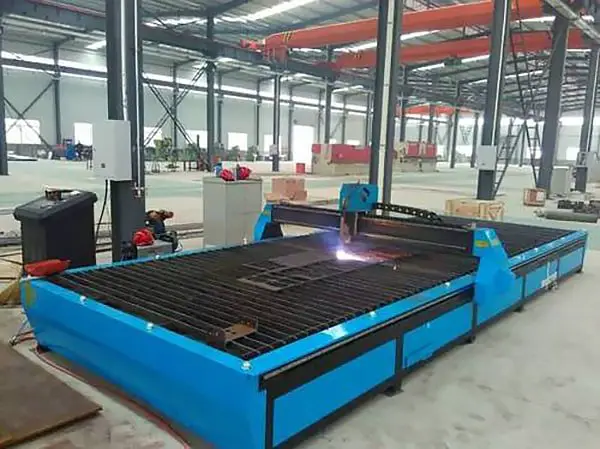
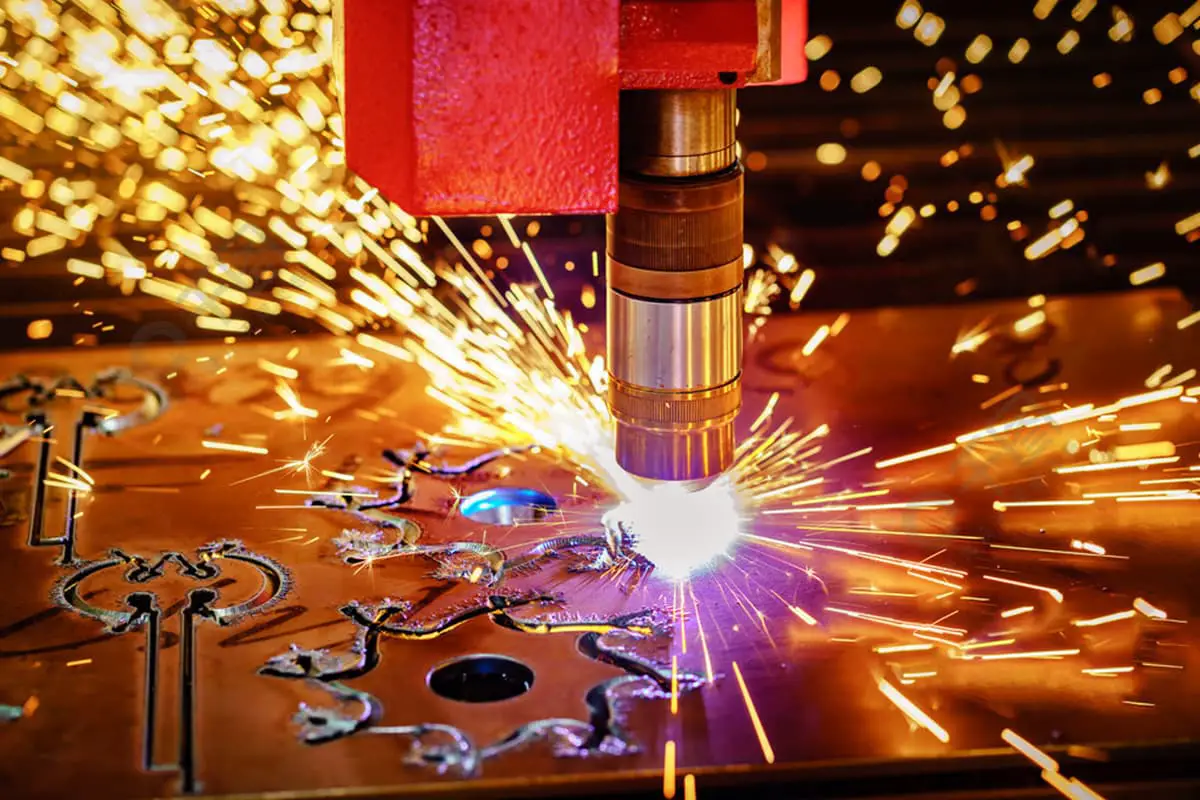
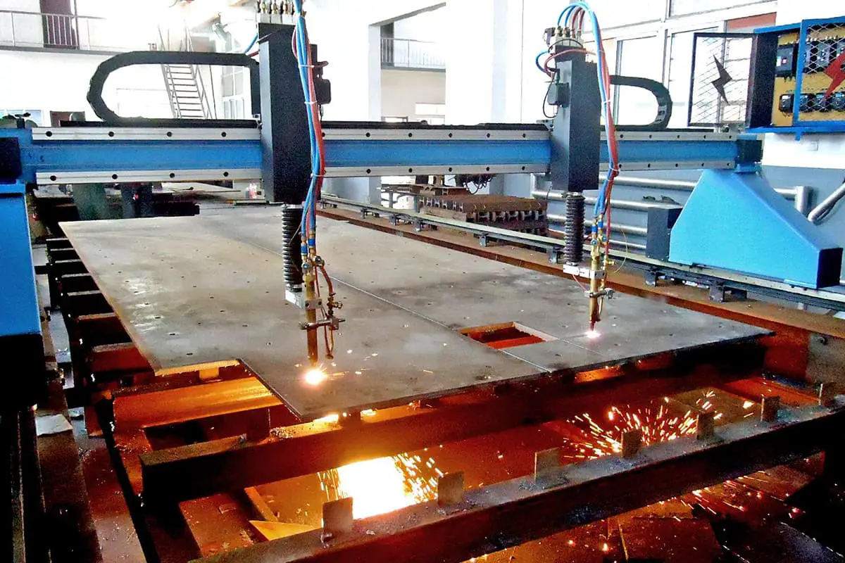
A plasma cutting machine is a machine that utilizes plasma cutting technology to process metal materials.
Industrial Applications
Plasma cutting is a processing method that utilizes the heat generated by a high-temperature plasma arc to partially or fully melt and evaporate the metal at the kerf, and uses the momentum of the fast-moving plasma to remove the molten metal and create the cut. This method is particularly effective for cutting non-ferrous metals, such as stainless steel, aluminum, copper, titanium, and nickel, which can be challenging to cut using oxygen cutting.
One of the main advantages of plasma cutting is its speed, especially when cutting thin metal sheets. Compared to oxygen cutting, plasma cutting can be up to 5 to 6 times faster when cutting ordinary carbon steel sheets. The cut surfaces are smooth and clean, with minimal thermal deformation and a small heat-affected zone.
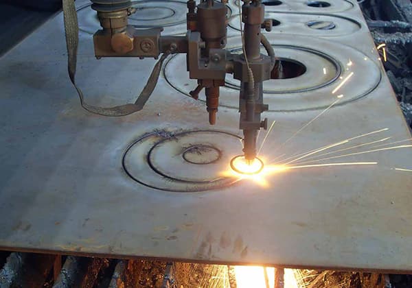
Plasma cutting machines are widely used in various industries, such as the automobile, locomotive, pressure vessel, chemical machinery, nuclear, general machinery, engineering machinery, steel structure, and shipping industries.
Working Gases
The advancement of plasma cutting technology has greatly impacted the cutting characteristics, quality, and speed of the plasma arc. The choice of working gas (the medium that conducts and carries heat for the plasma arc, excluding the melted metal in the cut) is crucial in this regard.
Common working gases for plasma arc include argon, hydrogen, nitrogen, oxygen, air, water vapor, and some blended gases.
Selection of plasma gas
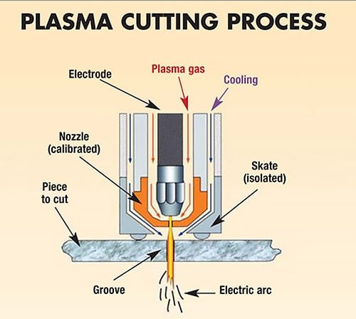
The gas into the plasma arc is called the ion stream.
Its main functions are as follows:
- A. It plays a certain role of heat insulation and insulation between the arc column and the inner wall of nozzle hole, compresses the arc and ensures the stable combustion of the arc.
- as the thermal conductor of ionization medium and arc, the cut metal is melted rapidly.
- blow out the melted metal at the slit to form a narrow and smooth slit.
- cooling protection for electrodes.
In light of the above effects of ionic gases, the following requirements should be taken into consideration when selecting gases:
- Easy arc initiation and stable arc: The gas should have a low ionization potential and poor thermal conductivity, and should not have a cooling effect on the arc. Monoatomic gas is better than diatomic gas in this regard.
- Good compression property of the arc: The gas should have good thermal conductivity, high heat capacity, and a strong cooling effect on the arc.
- Good heat carrying capacity: The gas should have the ability to transfer heat effectively to the workpiece. Diatomic gas, with its higher ionization potential, generally has better heat carrying capacity than monoatomic gas with low ionization potential.
- Ability to generate large momentum: The gas should have a large mass and density.
- Availability, affordability, and non-toxicity.
Some of the requirements listed above are contradictory, so the main requirements should be met based on specific circumstances. Currently, the gases commonly used in plasma arc cutting include nitrogen, argon, hydrogen, and their mixture gas, with nitrogen being the most commonly used.
Nitrogen is affordable and readily available, and its use is relatively safe. It is a diatomic gas that is endothermic when it decomposes in the high temperature of the arc.
N2->2N-1084000j/mol
When using plasma cutting, the type of working gas used can have significant impacts on the cutting characteristics, quality, and speed. Common working gases include nitrogen, argon, hydrogen, and mixed gases. Of these, nitrogen is the most widely used due to its low cost and ease of availability, as well as its ability to create favorable conditions for cutting thick materials.
Nitrogen, being a diatomic gas, decomposes into nitrogen ions when exposed to high temperatures in the plasma arc, releasing the heat absorbed during decomposition. This allows the plasma arc to reach high temperatures over a wide range of lengths, making it ideal for cutting materials with high thermal conductivity and poor liquid fluidity. The purity of the nitrogen used in plasma cutting should be no less than 99.5% to avoid oxidizing the electrode and burning out the nozzle.
Argon is a monoatomic gas with low ionization potential and stable arc combustion, but its high cost makes it a less practical option. Adding hydrogen to nitrogen or argon can improve the compression effect of the arc, leading to a narrower and smoother cut surface.
In air plasma cutting, compressed air is used instead of expensive gases, making it a more cost-effective option. The cutting speed with high current is much higher than that of flame cutting, and the cutting quality is also very good. For carbon steel plates below 25 mm, the cutting speed is 3-5 times faster, and for 5-10 mm thin plates, it’s 6-8 times faster. Air plasma cutting has replaced flame cutting in many applications due to its cost-effectiveness and good cutting quality.
How to choose the parameters of NC plasma cutting
Various plasma arc cutting process parameters directly affect the stability of the cutting process, cutting quality and effect.
The main cutting specifications are as follows:
1) Cutting current
The most important parameter of cutting speed and cutting is the cutting process.
Impact:
- When the cutting current increases, the arc energy increases, the cutting ability increases, and the cutting speed increases;
- With the increase of cutting current, the arc diameter increases and the arc becomes thicker, which makes the incision wider;
- If the cutting current is too high, the thermal load of the nozzle will increase, the nozzle will be damaged prematurely, and the cutting quality will naturally decline, even unable to cut normally.
So, when preparing for plasma cutting, it’s important to choose the appropriate cutting current and corresponding nozzle for the thickness of the material.
When selecting a power supply for plasma cutting, it’s important to avoid choosing a power supply that is either too large or too small.
Choosing a power supply that is too large is wasteful in terms of cutting cost, as it doesn’t utilize the full amount of current.
On the other hand, choosing a power supply with too small of a current in an effort to save cost is also not ideal, as it will not meet the required cutting specifications and can cause harm to the CNC cutting machine itself.
2) Cutting speed
The high temperature and energy of the plasma arc determine the cutting speed, which can be selected within the optimum range according to the equipment instructions or determined through experimentation. The cutting speed may vary depending on the thickness of the material, its properties (e.g. melting point, thermal conductivity, surface tension after melting), and the desired quality.
While maintaining the quality of the cut, the cutting speed should be increased as much as possible to improve productivity and reduce deformation and heat-affected areas. If the cutting speed is not appropriate, the opposite effect will occur, leading to increased slag adhesion and decreased cutting quality.
The following are the main manifestations:
If the cutting speed is moderately increased, the quality of the cut can be improved, meaning the cut becomes slightly narrower, the cut surface is smoother, and deformation is reduced.
If the cutting speed is too fast, the cutting linear energy is lower than the required value, and the jet in the cut cannot blow off the molten cutting material immediately, leading to a large amount of drag. This results in slag hanging on the cut, and the surface quality of the cut decreases.
When the cutting speed is too slow, because the cutting position is the anode of the plasma arc, to maintain arc stability, the anode spot or anode area must find a conductive current near the cutting seam closest to the arc. At the same time, it transfers more heat radially to the jet, causing the cut to widen. The molten material on both sides of the cut gathers and solidifies at the bottom edge, making it difficult to clean. Additionally, excessive heating and melting cause the upper edge of the cut to become rounded.
At very low speeds, the wide cut can even cause the arc to extinguish. Thus, good cutting quality and speed are inseparable.
3) Arc voltage
It is generally believed that the normal output voltage of the power supply is the cutting voltage for plasma cutting. The plasma machine typically operates at higher voltage for plasma arc, especially for air plasma cutting.
When the current is constant, an increase in voltage improves the arc enthalpy and cutting ability. A higher enthalpy reduces the diameter of the jet and increases the gas flow rate, resulting in faster cutting speed and better cutting quality.
No-load voltage and arc column voltage are important factors in plasma cutting power supply. The power supply must have a high enough no-load voltage to easily start the arc and maintain stable combustion of the plasma arc.
No-load voltage is usually in the range of 120-600V, while the arc column voltage is usually half of the no-load voltage. Increasing the arc column voltage enhances the power of the plasma arc, enabling the cutting of thicker metal plates at a faster speed.
The arc column voltage can be adjusted by changing the gas flow rate and increasing the internal shrinkage of the electrode, but it should not exceed 65% of the no-load voltage to maintain stability of the plasma arc.
4) Working gas and flow
The working gas in plasma cutting includes both cutting gas and auxiliary gas, and some equipment also requires an arc starting gas.
The appropriate working gas should be chosen based on the type of material being cut, its thickness, and the cutting method.
The cutting gas should not only form the plasma jet but also effectively remove the molten metal and oxides from the cut.
Having an excessive gas flow can take away too much heat from the arc, causing the length of the jet to shorten and a decrease in cutting ability and arc instability.
If the gas flow rate is too low, the plasma arc may lose its straightness, resulting in shallower cuts and an increase in slag formation.
It’s important that the cutting speed and gas flow rate are well-matched.
The plasma cutting machine typically controls the gas flow rate. The gas pressure used to cut a certain thickness of material should be chosen based on the manufacturer’s data, but in special applications, it may need to be determined through actual cutting tests.
The most commonly used working gases are argon, nitrogen, oxygen, air, and H35 (a mixture of argon and nitrogen).
Argon is unlikely to react with any metal at high temperatures and produces a stable plasma arc. The nozzle and electrode used have a long lifespan, but the voltage of the argon plasma arc is low, with limited enthalpy and cutting ability. This results in a 25% reduction in cutting thickness compared to air cutting.
Moreover, the surface tension of molten metal is higher in an argon-protected environment, about 30% higher than in a nitrogen environment, leading to more slag issues. Even if a mixture of argon and other gases is used, there is a tendency for slag to stick. As a result, pure argon is rarely used for plasma cutting.
Hydrogen is commonly used as an auxiliary gas in combination with other gases. For instance, the popular gas H35 (35% hydrogen volume, the rest is argon) is one of the most effective gases in plasma arc cutting, which owes much of its power to hydrogen.
Hydrogen significantly boosts the arc voltage, resulting in a plasma jet with a high enthalpy. When combined with argon, the cutting ability of the plasma jet is significantly enhanced.
Argon and hydrogen are commonly used as cutting gas for metal materials with thickness greater than 70mm. By further compressing the argon + hydrogen plasma arc with a water jet, higher cutting efficiency can be achieved.
Nitrogen is a commonly used working gas. When operating under higher power supply voltage, the nitrogen plasma arc has better stability and higher jet energy compared to argon.
When cutting materials with high liquid metal viscosity, such as stainless steel and nickel base alloy, the amount of slag on the lower edge of the cut is minimal.
Nitrogen can be used on its own or in combination with other gases. For example, nitrogen or air is often used as a working gas in automatic cutting.
These two gases have become the standard for high-speed cutting of carbon steel.
In some cases, nitrogen is also used as the starting gas for oxygen plasma arc cutting.
Oxygen can enhance the cutting speed of low carbon steel.
The use of oxygen for cutting results in imaginative cutting modes such as flame cutting.
A high temperature and high energy plasma arc results in faster cutting speed, but it must be paired with the use of high temperature oxidation-resistant electrodes and anti-impact protection to extend the electrode’s lifespan during the arcing process.
The air is comprised of approximately 78% nitrogen by volume, making air cutting an imaginative method for slag and nitrogen cutting. The air also contains about 21% oxygen.
Due to the presence of oxygen, cutting low carbon steel with air is also very fast. Additionally, air is the most cost-effective working gas.
However, when air cutting is utilized on its own, issues such as slag adhesion, oxidation of the cut, and increased nitrogen can arise.
Furthermore, the short lifespan of the electrode and nozzle will also impact work efficiency and increase cutting costs.
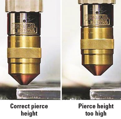
5) Nozzle height
Nozzle height refers to the distance between the end face of the nozzle and the cutting surface, and is a component of the total arc length.
Typically, the distance ranges from 4 to 10 mm.
Similar to the electrode, it’s crucial to maintain an appropriate nozzle height in order to maximize plasma arc cutting efficiency. Otherwise, cutting efficiency and quality will be reduced or the cutting nozzle may burn out.
Since plasma arc cutting typically uses power supplies with constant current or steep drop external characteristics, the current remains relatively unchanged even as the nozzle height increases. However, this does result in an increase in arc length and a corresponding increase in arc voltage, thereby improving arc power. At the same time, the longer arc length exposed to the environment also results in increased energy loss from the arc column.
These two factors often counteract each other, reducing effective cutting energy and cutting ability. This is often indicated by a weakened cutting jet blowing force, increased residual slag at the bottom of the cut, over-melted and rounded upper edge.
Additionally, the diameter of the plasma jet expands as it leaves the nozzle, and increasing the nozzle height will result in a wider cut. It’s therefore advantageous to choose the smallest possible nozzle height to improve cutting speed and quality.
However, if the nozzle height is too low, it may result in double arc phenomenon.
By using a ceramic external nozzle, the nozzle height can be set to zero, with the nozzle end face directly contacting the cutting surface, which results in improved performance.
5) Arc power
In order to achieve high-pressure plasma arc cutting, cutting nozzles are designed with a smaller diameter, longer channel length, and improved cooling, which increases the current passing through the effective section of the nozzle, resulting in an increase in the arc power density.
However, this also increases the power loss of the arc. As a result, the actual effective energy for cutting is smaller than the output power of the power supply, with a loss rate typically between 25% and 50%.
Some methods, such as water-compressed plasma arc cutting, have a higher energy loss rate, which must be considered when designing cutting process parameters or calculating cutting costs.
For instance, most metal plates used in industry have a thickness of less than 50 mm. Conventional plasma arc cutting in this thickness range often results in a cut with a wide top and narrow bottom, which decreases the accuracy of the incision size and increases the amount of subsequent processing.
When oxygen and nitrogen plasma arc is used to cut carbon steel, aluminum, and stainless steel, the perpendicularity of the end edge is better with increasing material thickness within the range of 10 to 25 mm. However, when the plate thickness is less than 1 mm, the incision angle error increases from 3 to 4 degrees to 15 to 25 degrees as the plate thickness decreases.
This phenomenon is thought to be caused by an unbalanced heat input from the plasma jet on the cutting surface, meaning the energy release of the plasma arc in the upper part of the cut is greater than in the lower part. This energy imbalance is closely related to various process parameters, such as the plasma arc compression degree, cutting speed, and the distance between the nozzle and the workpiece.
Increasing the compression degree of the arc can make the high-temperature plasma jet longer and create a more uniform high-temperature area, and increasing the jet speed can reduce the width difference between the top and bottom of the incision.
However, overcompression of the conventional nozzle often leads to double arc, which not only consumes the electrode and nozzle but also decreases the cutting quality.
Additionally, too high cutting speed and too large nozzle height can result in an increased gap width.
6) Electrode shrinkage
The term “internal shrinkage” refers to the distance between the electrode and the end face of the cutting nozzle. Maintaining a proper distance allows for good compression of the arc in the cutting nozzle, resulting in a plasma arc with concentrated energy and high temperature for effective cutting.
If the distance is too small or too large, the electrode will burn excessively, the cutting nozzle will burn out, and the cutting ability will be reduced. The typical internal shrinkage is 8-11mm.
Selection of Electrode and Polarity:
The electrode used in plasma arc cutting must have low burning loss to ensure the stability of the cutting process. Tungsten, which has a high melting point, still has a significant amount of burning loss and cannot guarantee a stable cutting process.
Adding a small amount of low ionization potential elements, such as thorium, to tungsten reduces the burning loss of the thorium tungsten electrode significantly. This is because the thorium tungsten electrode has strong electron thermal emission, causing most of the energy at the electrode end face to escape as electrons, thereby lowering the temperature of the electrode end face.
Additionally, the thorium tungsten electrode has a weak effect on oxygen, reducing its burning loss at high temperature. The commonly used thorium tungsten electrode contains 1.5% to 2.5% thorium. However, thorium is radioactive, so non-radioactive cerium tungsten or lanthanum tungsten electrodes are widely used as alternatives.
In plasma arc cutting, direct polarity is commonly used, connecting the thorium tungsten rod to the negative electrode and the workpiece to the positive electrode. This benefits electron thermal emission, stabilizes the isoelectric arc combustion, and reduces electrode burning loss.
In addition to the general form of plasma cutting methods, derived forms include water compression plasma cutting.
The most commonly used methods are general plasma cutting and air plasma cutting.
General cutting
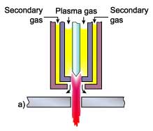
General plasma cutting does not require a protective gas as the working gas and cutting gas are expelled from the same nozzle. When starting the arc, a small flow of ionic gas is expelled as the ionization medium. During the cutting process, a stream of air is also expelled to remove the molten metal.
Air cutting
In general, air plasma cutting uses compressed air as the ionizing gas. This method is cost-effective and has a convenient source of gas. Compressed air is heated, decomposed, and ionized in the arc, creating oxygen which then cuts the metal and produces a chemical exothermic reaction that accelerates the cutting speed. The fully ionized air plasma has high enthalpy, leading to a large arc energy and fast cutting speed.
Cutting equipment
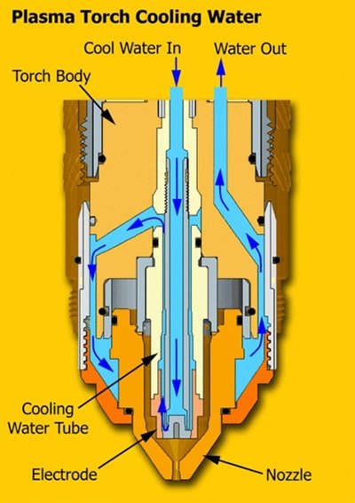
The plasma cutting system primarily consists of a gas supply unit, water unit, power supply, and cutting torch. The water-cooled torch also requires a cooling circulating water unit.
(1) Air Supply Unit
The main equipment of the air supply device for air plasma arc cutting is an air compressor with a power rating of over 1.5 kW, and the required air pressure is between 0.3-0.6 MPa. If a different gas is required, bottled gas can be used after decompression.
(2) Power Supply
For plasma cutting, a DC power supply with either a steep drop or constant current characteristic is used. To ensure a satisfactory arc starting and stabilization effect, the no-load voltage of the power supply is generally twice that of the arc voltage. A typical cutting power supply has a no-load voltage of 350-400 V.
(3) Cutting Gun
The design of the cutting gun depends on the current level of the cutting gun. For cutting guns rated below 60 A, an air-cooled structure is typically used, while for those above 60 A, a water-cooled structure is used. The electrode in the cutting gun can be made of pure tungsten, thorium tungsten, tungsten bell rod, or an inlaid electrode. Cast tungsten is a preferred electrode material as it is simple to use and can cut all types of non-metallic materials.
Safety protection
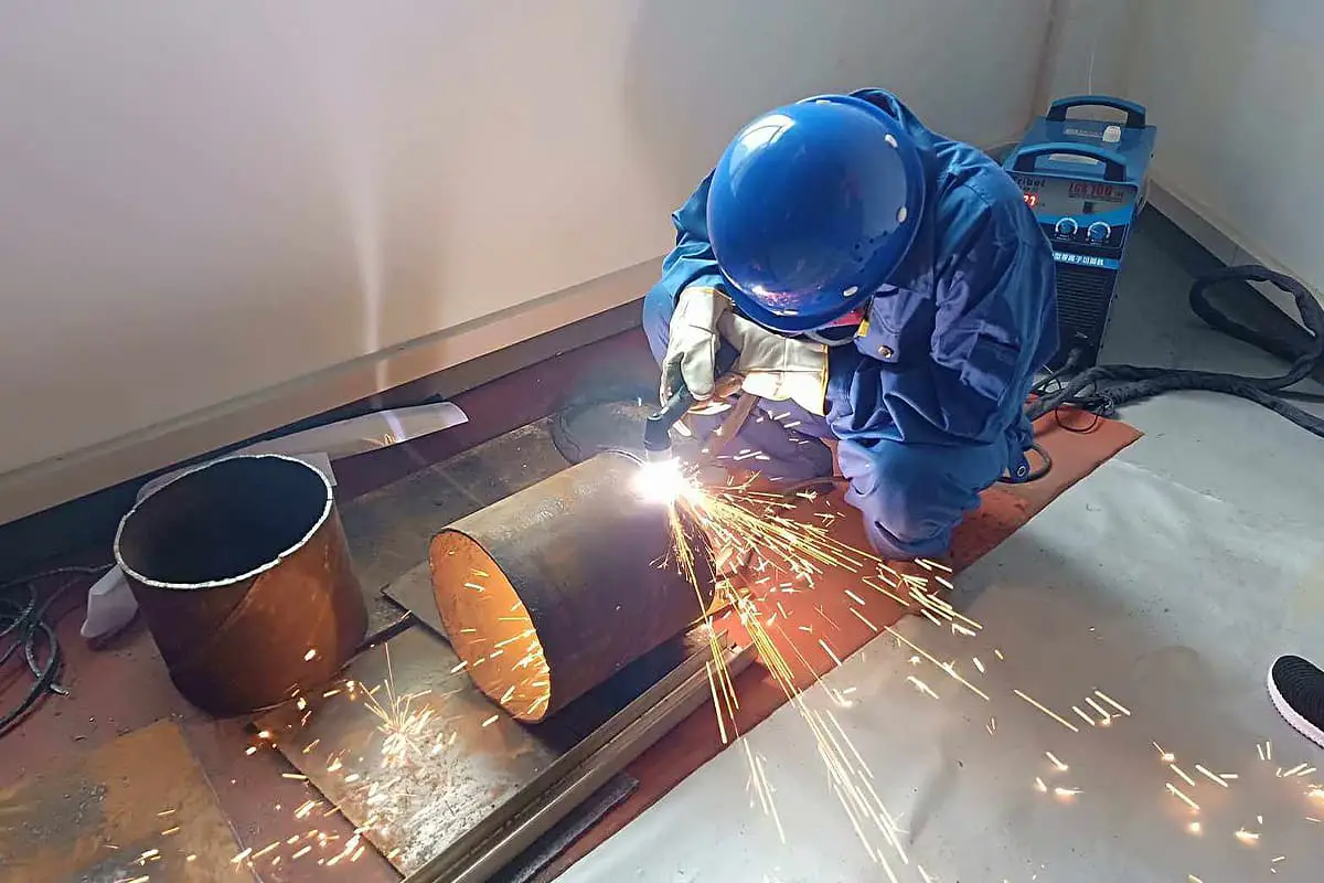
The bottom part of a plasma cutting setup should be equipped with a water tank. During the cutting process, the workpiece should be submerged in water to minimize the toxicity of the smoke to human health.
It is important to avoid direct visual exposure to the plasma arc during plasma cutting. Protective glasses and a face mask should be worn to prevent eye and skin burns from the intense light of the arc.
Plasma cutting generates a large amount of toxic gas, so proper ventilation and wearing multi-layer filtering dust masks is crucial to minimize exposure.
In addition, it’s important to wear protective clothing, such as a towel, gloves, and foot sheath, during plasma cutting to prevent skin burns from sparks.
It’s worth noting that the high frequency and electromagnetic radiation generated by the high frequency oscillator during plasma cutting may have harmful effects on the body, and some long-term practitioners have reported infertility symptoms. Although the medical and industrial communities have not reached a definitive conclusion on this matter, it is still advisable to take protective measures.
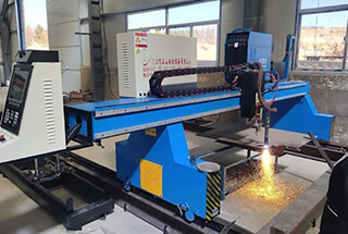
How to choose CNC plasma cutting machine
1.Price
When considering purchasing a plasma cutter, it is important to take into account the budget factor. Ignoring the budget can result in choosing a product that exceeds the budget, even if it meets the desired specifications.
Plasma cutters are currently divided into two categories: domestic and imported. Domestic plasma cutters have three specifications: low, medium, and high, and are generally acceptable to most users.
Imported plasma cutters are much more expensive, with prices several times or even dozens of times higher than domestic counterparts. Consumables such as cutting nozzles and electrodes are also more expensive.
While imported plasma cutters offer better cutting results compared to domestic models of the same specification, their high cost and ongoing expenses can make them difficult for many businesses to accept.
2.Cutting thickness
No matter the type of plasma used, it has its own optimal cutting size range. It is commonly known that low-power plasma is best suited for cutting thin plates. However, if the plasma power is too high, it is not suitable for cutting thin plates.
Currently, 40-60A domestic plasma cutting is widely used for cutting steel plates below 2mm, while imported plasma is used occasionally but in limited quantities due to its high cost. It is important to note that for steel plates below 2mm, only high-speed desktop plasma cutting machines are suitable and other models, such as portable and gantry types, are not.
If the steel plate is thicker than 2mm, it is not restricted and can be cut using portable or gantry machines. For steel plates between 2-16mm, portable and gantry machines can be used. However, for thicknesses of 25mm or thicker, only gantry machines are suitable.
3.Cutting materials
It is widely known among personnel involved in metal processing that plasma cutting is the preferred method for cutting stainless steel and other alloy materials. On the other hand, carbon steel plates are mainly cut using the flame cutting method. As a result, when dealing with stainless steel, it is essential to have a plasma cutting machine. It cannot be cut using the flame cutting method.
Advantages of NC plasma cutting machine
1.Better cutting quality
The quality of cutting is mainly impacted by factors such as slag, heat-affected zone, top fillet, and cutting angle. Among these, plasma cutting outperforms flame cutting in terms of slag and heat-affected zone, as there is no residual slag on the edge of plasma-cut pieces, and the heat-affected zone is significantly smaller.
2.Scum
The plasma process involves using high-temperature charged gas to melt metal and blow away the melted material from the cutting surface. On the other hand, flame cutting uses the chemical reaction between oxygen and steel for cutting, resulting in the production of iron oxide slag or scum.
Due to these differences in technology, plasma cutting produces less scum and the attached scum is easier to remove. These scum can be easily cleared without grinding or additional processing, reducing the time needed for secondary processing. This results in higher productivity, as fewer grinding operations are required.
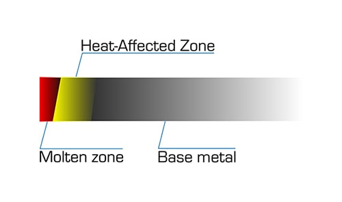
3.Heat affected zone
The size of the heat affected zone (HAZ) is a critical factor in metal cutting. When metal is exposed to high temperatures, it can change its chemical structure, causing the edge to darken (take on a tempering color) and warp. If the heated edge is not removed, the workpiece may not be suitable for secondary welding.
The speed at which the torch moves directly impacts the size of the heat affected zone. Plasma cutting is known for its rapid cutting capabilities, which results in a smaller heat affected zone, reducing the time required for secondary processing to remove the heated edge.
Flame cutting users may also take notice of the fire color. While the heat affected zone is not visible from the outside, the tempering color can be seen and can change the color of the metal. Like with the heat affected zone, the rapid cutting of plasma results in a smaller area of fire color.
4.Higher productivity
With CNC plasma cutting and piercing speeds up to 8.5 times faster than flame cutting, significant productivity gains can be achieved, not to mention the time saved in preheating and secondary processing.
5.Lower cost per part
When evaluating costs, it is essential to distinguish between operational costs and the cost per part or per meter. To determine the actual cost of cutting a part, it is important to consider various factors such as the running cost per meter and the cost per part.
The running cost per meter is calculated by dividing the total cost of cutting per hour by the total length that can be cut in one hour. The costs involved in cutting include consumable parts, electricity, gas, labor, and sustainability expenses. On the other hand, the cost per part is determined by multiplying the total length of cutting required to produce a part by the running cost per meter.
Since the plasma cutting system operates faster, it is able to produce more parts in a given time, reducing the cost per part significantly. For handheld cutting, it is advisable to calculate the cost of each job or task to accurately evaluate the cost savings. The cost of the job can be calculated by multiplying the running cost per hour by the total time required to complete the task.
When considering flame cutting, it is necessary to factor in the preheating time and the prolonged time for secondary processing, as these add to the overall time required to complete the job.
6.Higher profitability
The lower cost per part of the plasma system directly results in increased profitability. Each part that is cut using this method can lead to cost savings, thereby increasing the profit margin. The greater the number of parts that can be cut per hour, the greater the overall increase in profits will be.
7.Easier to use
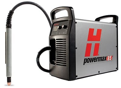
For those who use flame cutting, it takes time and practice to master the adjustment of flame chemical parameters and to maintain the chemical balance of the flame. On the other hand, Hypertherm’s Powermax series operates using compressed air, eliminating the need for mixing or regulating gases.
If you are using a mechanical plasma system with CNC or an automatic gas console, all parameters will be pre-set by the manufacturer and there is no need for manual adjustment of the gas.
Additionally, the Powermax handheld plasma system features drag-cutting capability, which allows the operator to move the torch along the metal surface without having to maintain a specific distance, a crucial aspect in flame cutting.
Furthermore, plasma cutting systems are easier to use, with their straightforward control devices, making it easier for operators to learn and cut according to templates and patterns, especially those with curves. The ease of use results from the lack of gas adjustment and the drag cutting capability.
8.Higher flexibility
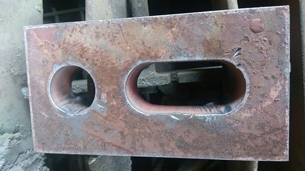
The plasma system is capable of cutting any conductive metal, including stainless steel, aluminum, copper, and brass, whereas the flame cutting machine is limited to cutting low carbon steel only through the chemical reaction between oxygen and iron. The plasma system is also versatile and can be used for planing, marking, or even cutting rusty, painted, or stacked metal.
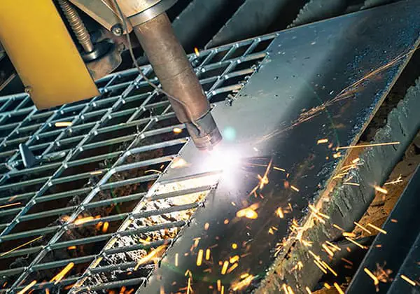
Additionally, the plasma system is capable of performing groove cutting or steel mesh cutting, which is challenging for flame cutting to accomplish.
9.Higher security
The fuel used in flame cutting is a mixture of oxygen and gas, with the most commonly used fuels being acetylene, propane, MAPP, propylene, and natural gas. Among these, acetylene is the most widely used as it produces a higher flame temperature and faster perforation speed compared to others. ‘However, acetylene is an unstable and highly flammable gas that is very sensitive to high pressure, temperature, and even static electricity. An acetylene explosion can cause property damage in the tens of thousands of dollars and result in serious injury to people nearby.
In contrast, some plasma systems, such as the Powermax series by Hypertherm, operate using compressed air and do not require the use of flammable gases. Hypertherm’s HPR and HSD plasma systems can also use a variety of gases, including air, oxygen, and nitrogen, which are more stable and do not require special treatment.
It should be noted that all forms of thermal cutting produce some odor and noise, but water cutting machines and CNC plasma cutting systems can significantly reduce the odor and noise produced. Conversely, flame cutting should not be performed underwater due to the risk of explosion.
Safety guarantee of plasma cutting machine operation
(1) Operators must wear protective gear including masks, welding gloves, hats, filter dust masks, and sound-insulating earmuffs. It is strictly prohibited to look directly at the plasma arc without wearing protective glasses, and bare skin should not come into contact with the plasma arc.
(2) When cutting, the operator should stand on the side where the wind is blowing, as this can reduce the area that the air is being drawn from below the table.
(3) If the no-load voltage is too high during cutting, check the electrical grounding, the connection to ground, and the insulation of the torch handle. Insulate the workbench from the ground or install a no-load circuit breaker in the electrical control system.
(4) The high-frequency generator should be equipped with a shielding shield. The high-frequency circuit should be cut off immediately after the high-frequency arc is struck.
(5) The use of thorium and tungsten electrodes must comply with article JGJ33-2001 of 12.7.8.
(6) Personnel involved in cutting operations must wear protective gear according to regulations and take safety measures to prevent electric shock, falls from heights, gas poisoning, and fire.
(7) Electric welding machines used on the site should be protected from rain, moisture, and sun and equipped with firefighting equipment.
(8) When welding or cutting at a high altitude, the safety belt must be fastened, fire prevention measures should be taken around and under the welding and cutting areas, and a designated supervisor should be assigned.
Daily maintenance of plasma cutting machine
1.Assemble the cutting torch correctly
Ensure correct and careful installation of the cutting torch to guarantee proper fit of all parts and proper flow of gas and cooling air. Place all components on a clean piece of flannel to prevent dirt from adhering to them.
2.The consumable parts should be replaced in time before they are completely damaged
The consumable parts should not be replaced after being completely damaged because seriously worn electrodes, nozzles, and vortex rings can produce an uncontrollable plasma arc, which can easily cause serious damage to the cutting torch.
Therefore, when a decline in cutting quality is first noticed, consumable parts should be promptly inspected.
3.Clean the connecting thread of cutting torch
When replacing consumable parts or performing daily maintenance and inspection, it is necessary to ensure that the internal and external threads of the cutting torch are clean. If necessary, the connecting threads should be cleaned or repaired.
4.Clean the contact surface between electrode and nozzle
In many cutting torches, the contact surface between the nozzle and electrode is a charged contact surface. If there is dirt on these contact surfaces, the cutting torch cannot work properly.
5.Check the gas and cooling gas every day
Check the flow and pressure of gas and cooling air every day. If the flow is insufficient or there is a leakage, shut down the machine immediately to eliminate the fault.
6.Avoid cutting torch collision damage
To avoid collision damage to the cutting torch, it is necessary to program correctly and avoid system overrun. Installing an anti-collision device can effectively prevent damage to the cutting torch during a collision.
7.The most common causes of cutting torch damage
① Cutting torch collision.
② Destructive plasma arc due to consumable damage.
③ A destructive plasma arc caused by dirt.
④ Destructive plasma arc caused by loose parts.
8.Precautions
① Do not grease the cutting torch.
② Do not overuse O-ring lubricant.
③ Do not spray splash proof chemicals while the protective sleeve is still on the cutting torch.
④ Do not use manual cutting torch as hammer.
Operation precautions of plasma cutting machine
1.1 In order to reduce energy consumption and improve the service life of the nozzle and electrode, “low-grade” cutting should be used when cutting thinner workpieces.
1.2 When the “cutting thickness selection” switch is set to “high-grade,” non-contact cutting type cutting (except for special cases) should be used, and the water cutting torch should be preferred.
1.3 When the “thickness selection” switch needs to be changed, the power switch of the host must be turned off first to prevent damage to the parts.
1.4 When installing, disassembling, or moving the host, the power supply must be turned off first to prevent accidents.
1.5 The power switch of the host machine should be turned off before accessories and components on the host can be installed and removed (such as the cutting torch, cutting ground wire, electrode, nozzle, distributor, pressure cap, protective sleeve, etc.). Avoid repeatedly and quickly opening the torch switch to prevent damage to the arc striking system or related components.
1.6 When it is necessary to start arc cutting from the middle of the workpiece, stainless steel up to 20mm in thickness can be directly pierced and cut.
The method is as follows:
Place the cutting torch on the starting point of the cutting seam, and position the axis of the cutting torch nozzle at an angle of about 75° with the workpiece plane. Then turn on the cutting torch switch to start arc piercing.
At the same time, slowly adjust the angle between the nozzle axis and the workpiece surface until the cut-through workpiece is adjusted to 90°.
After cutting through the workpiece, it can be cut normally along the cutting seam direction.
However, if the thickness is more than the above, it is necessary to drill a small hole (diameter not limited) at the starting point of cutting to start arc cutting from the small hole. Otherwise, it is easy to damage the cutting torch nozzle.
1.7 The mainframe has a continuous working rate of 70% (when the “cutting thickness selection” switch is set to a low level, the continuous work can be close to 100%).
If the continuous working time is too long and the temperature of the main engine is too high, the temperature protection system will automatically shut down, and it must be cooled for about 20 minutes before it can continue to work.
1.8 If the compressed air pressure is lower than 0.22 MPa, the equipment will immediately be in a protection shutdown state.
At this time, the gas supply system should be overhauled. After troubleshooting, the pressure can be resumed to 0.45 MPa.
1.9 If the three-phase input power supply is out of phase, the main engine will not work properly, and the “phase loss indication” red light of some models will turn on.
It is necessary to eliminate the fault before normal cutting.
1.10 For water-cooled machines, the water tank must be filled with tap water, and the power plug of the water pump must be plugged in.
1.11 Turn the power switch to the “start” position. If the “insufficient air pressure” indicator is on, adjust it to 0.45MPa as required, then the indicator should be off. The direction of fan rotation should match the sign direction. The water pump direction of the water cooler should also meet the requirements, otherwise, the “insufficient water pressure” indicator light will be on, and the input power phase should be adjusted.
1.12 According to the thickness of the workpiece, turn the “cutting thickness selection” switch to the corresponding position and select the appropriate cutting torch. The cutting torch has various specifications, from small to large, according to the range of use. Do not exceed the rated current range, or it will be damaged. Place the cutting torch at the cutting starting point of the workpiece and press the torch switch. If the torch is not ignited for one time, press the torch switch again. The arc striking is successful and the cutting starts.
1.13 Every four to eight hours of operation (the interval time depends on the dryness of compressed air), the drain screw of the “air filter pressure reducer” should be loosened to drain the accumulated water, so as to prevent excessive water from entering the machine or cutting torch and causing failure.
1.14 When the water cooling system is in poor circulation, the main engine will be in the protection shutdown state. At this time, it should be checked and solved according to the methods described in the relevant chapters. After the water pressure returns to normal, the water-cooled cutting torch can continue to be used.
1.15 When working in a cold environment, it is important to note that when the ambient temperature is below freezing point, water cooling method should not be used for cutting. Otherwise, the circulating water cooling system will not work properly, and the water cooling cutting torch may be damaged.
Preparation before operation
2.1 After connecting the equipment (please pay special attention to the safety grounding wire), carefully check and proceed to the next operation if everything is normal.
2.2 Close the power supply switch to supply power to the host. Note: the input AC current is about 65A, which should not be too small; otherwise, the host cannot work properly. Check that the fan in the main engine meets the requirements; otherwise, adjust the input power phase until the steering direction is consistent.
2.3 Set the “power switch” of the host to the “on” position. At this time, the “power indicator” light should be on. However, the “lack of phase indicator” light should not be on; otherwise, the three-phase power supply has a phase loss phenomenon, which needs to be checked and resolved.
Note: if the main engine shell is not properly connected to the safety ground wire, the phase loss indicator may display wrong results.
2.4 Supply air to the main engine and place the “gas test” and “cutting” switches in the “gas test” position. At this time, compressed air should be ejected from the cutting torch nozzle. After a three-minute test, the red light of “insufficient air pressure” should not be on.
Check that the indication value of the pressure gauge on the “air filter reducer” should not be lower than 0.42MPa. Otherwise, it indicates that the air source pressure is less than 0.45MPa or the flow is less than 300L/min. It may also be that the air supply pipeline is too small, and the air pressure drop is too large.
If there are above problems, check and resolve them. Additionally, please pay attention to whether the “air filter pressure reducer” is out of balance. If so, it should be readjusted.
The adjustment method is as follows:
Rotate the handle clockwise to increase the pressure, otherwise it will decrease. Adjust the indication value on the pressure gauge to 0.42MPa. If the air supply is normal, the “insufficient air pressure” indicator light will go out. At this time, place the “cutting” and “gas testing” switch to the “cutting” position.
3.1 Manual Non-Contact Cutting:
3.1.1 Contact the cutting torch roller with the workpiece and adjust the distance between the nozzle and the workpiece plane to 3-5mm (when the host machine is cutting, set the “thickness selection” switch to high level).
3.1.2 Turn on the cutting torch switch to ignite the plasma arc. After cutting through the workpiece, move towards the cutting direction at an average speed. The cutting speed is: cutting through is the premise, which should be fast rather than slow. Too slow will affect the quality of incision and even break the arc.
3.1.3 After cutting, turn off the torch switch, and the plasma arc will be extinguished. At this time, compressed air will be ejected to cool the cutting torch. After a few seconds, the spray will stop automatically. Remove the cutting torch and complete the whole cutting process.
3.2 Manual Contact Cutting:
3.2.1 When the “thickness selection” switch is set at low gear, it can be used when cutting thin plate by a single machine.
3.2.2 Place the torch nozzle at the starting point of the workpiece to be cut, turn on the torch switch, ignite the plasma arc, cut through the workpiece, and then move uniformly along the cutting seam direction.
3.2.3 After cutting, open and close the torch switch. At this time, the compressed air is still ejecting. After a few seconds, the spraying will stop automatically. Remove the cutting torch and complete the whole cutting process.
3.3 Automatic Cutting:
3.3.1 Automatic cutting is mainly suitable for cutting thick workpieces. Select the “thickness selection” switch position.
3.3.2 After the cutting torch roller is removed, the cutting torch is firmly connected with the semi-automatic cutting machine, and there are connecting pieces in the attached accessories.
3.3.3 Connect the power supply of the semi-automatic cutting machine, and install the guide rail or radius rod according to the shape of the workpiece (if the guide rail for linear cutting is used, if the circular or circular arc is cut, the radius rod should be selected).
3.3.4 If the torch switch plug is removed, replace the remote control switch plug (provided in the attached accessories).
3.3.5 Adjust the walking speed according to the thickness of the workpiece. The “reverse” and “forward” switches on the semi-automatic cutting machine are placed in the cutting direction.
3.3.6 Adjust the distance between the nozzle and the workpiece to 3~8mm and adjust the nozzle center position to the starting strip of the workpiece cutting seam.
3.3.7 Turn on the remote control switch. After cutting through the workpiece, turn on the power switch of the semi-automatic cutting machine to cut. In the initial stage of cutting, attention should be paid to the cutting seam at any time and adjusted to the appropriate cutting speed. And pay attention to whether the two machines work normally at any time.
3.3.8 After cutting, turn off the remote control switch and the power switch of the semi-automatic cutting machine. So far, the whole cutting process is completed.
3.4 Manual Circle Cutting:
Based on the material and thickness of the workpiece, select the single machine or parallel machine cutting mode, and choose the corresponding cutting method. Tighten the crossbar in the screw hole on the cutting torch holder.
If the length of one piece is not enough, it can be connected to the required radius length one by one. After that, the distance between the tip and the cutting torch nozzle can be adjusted according to the radius length of the workpiece (consider the slotting width).
Once the adjustment is complete, tighten the top fastening screw to prevent loosening, and loosen the knurled screw of the cage.
At this point, the workpiece can be cut into a round shape.