Choosing the Right Quenching Cooling Medium: 40 Years of Experience
Have you ever wondered why the cooling medium used in quenching is so critical? Choosing the right quenching cooling medium can make or break the internal quality and shape of…
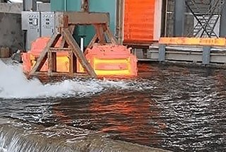
Why do some metals cool unevenly during quenching, leading to defects? The phenomenon of steam film formation during quenching is a crucial factor. This article explores how the steam film affects the cooling process and introduces advanced theories and experiments to understand and control this phenomenon. By reading further, you’ll gain insights into optimizing quenching processes to enhance metalwork quality and consistency.
There are various methods to assess the cooling capacity of a quenching medium, including the quenching intensity method, hot wire method, hardness U curve method, magnetic test method, among others. The cooling curve method is considered to be the best laboratory measurement method and is widely used.
However, it’s important to note that the actual cooling curve of a workpiece during quenching may differ from the one obtained from tests. This is because the heat transfer process from the workpiece to the medium during quenching is influenced by not only the material of the workpiece, but also its size and shape.
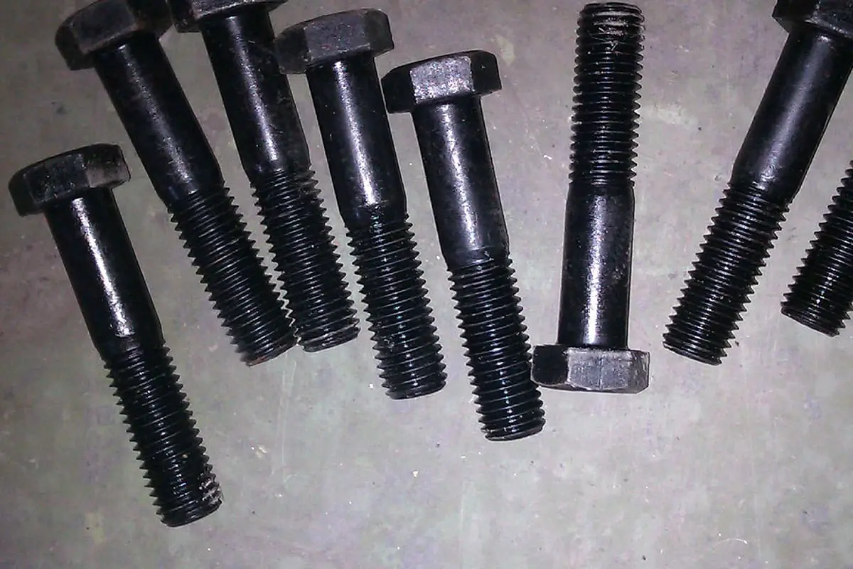
For instance, testing a general rapid quenching oil using a standard probe will typically show the vapor film stage, but when the same oil is used as a quenching medium for small fasteners, the vapor film stage may not be visible.
Despite these differences, testing the cooling characteristic curve of a quenching medium using standard methods is still valuable for comparing and selecting different mediums and monitoring the performance of the medium over time.
The cooling characteristic curve is widely used currently to evaluate the cooling properties of quenching cooling media, determine the degree of aging of the medium, and guide the heat treatment process.
The most commonly used test methods are:
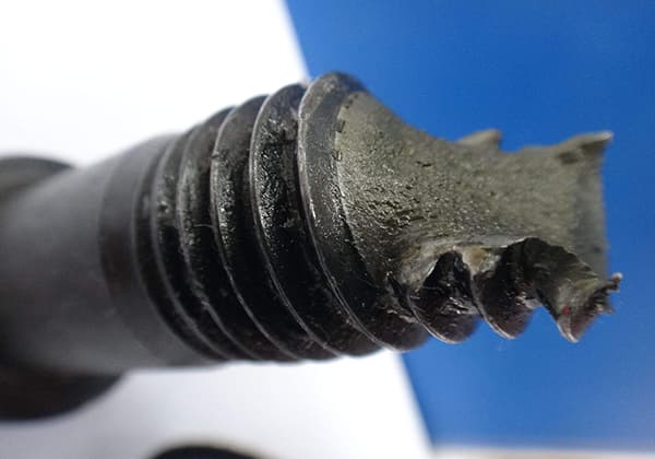
Heating a probe of a specific size and material to over 800°C, then immersing it in the quenching cooling medium of a specific temperature.
Using a thermocouple at the center of the probe to directly record the temperature change at the center of the probe over time, and deriving the curve to determine the cooling rate at different temperatures.
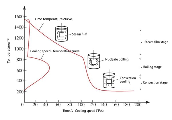
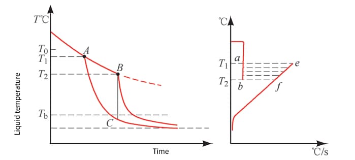
Based on the measured cooling characteristic curve, the cooling process is typically divided into three stages (refer to Fig. 1):
Steam film stage (when the workpiece is first immersed in the medium, its temperature is high, and the medium around the workpiece rapidly vaporizes to form a stable steam film that wraps the surface of the workpiece. At this time, cooling is slow due to poor heat conduction of the steam film);
Boiling stage (as the temperature of the workpiece decreases, the steam film becomes unstable and quickly leaves the surface of the workpiece in the form of small bubbles, taking away heat. This stage has the fastest cooling rate);
Convection stage (as the surface temperature of the workpiece decreases further, boiling stops when it drops below the boiling point of the medium, and the convection stage begins, relying on convective heat transfer).
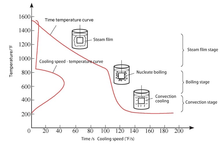
Fig. 1 Cooling characteristic curve and three stages of quenching
However, the cooling curve only measures the change in the core temperature of the probe over time and does not accurately reflect the temperature change at the surface.
To address this issue, Dr. Zhang Kejian introduced the “four stages” theory, which posits that there should be an “intermediate stage” between the steam film stage and the boiling stage to describe the coexistence of boiling and steam film phenomenon on the workpiece surface after the “advanced expansion point” appears (refer to Fig. 2).
This theory highlights the complexity of the cooling process of a workpiece in a quenching cooling medium and shows that it cannot be fully described by the cooling curve measured by a thermocouple at the center of the probe.
However, simply understanding the complexity of the steam film breaking process is not sufficient in gaining insight into the underlying causes of steam film formation and breaking, or in providing guidance for heat treatment practitioners.
Kobasko proposed the use of the critical heat flux concept from boiling heat transfer to evaluate the cooling performance of quenching cooling media, which can offer more support for medium development.
| Phase name | Theory division | Actual division |
| Vapor blanket stage | Above T0 | Above T1 |
| Intermediate stage | T0~T* | T1~T2 |
| Boiling stage | T*~T | T2~Tb |
| Convection stage | Tb~liquid temperature | Tb~liquid temperature |
Fig. 2 “Four Stage” Theory of Quenching
Fig. 3 illustrates the change in surface heat flow density and three successive stages during a continuous heating process, as the metal surface temperature increases and the wall superheat (difference between the surface temperature and boiling point of the medium) increases, as well as the change in thermal conductivity α of the medium during this process.
However, quenching and cooling is a cooling process, and the corresponding changes in heat flow density and thermal conductivity should be from the top right to the left of Fig. 3.
Additionally, there is a brief transient boiling process during this time (refer to Fig. 4).

Fig. 3 Boiling phenomenon and changes of heat flux and thermal conductivity during heating

Fig. 4 Instantaneous Boiling Phenomenon at the Initial Stage of Quenching Process
In the years 1926-1930, French conducted numerous experiments to study the instantaneous boiling process.
The findings showed that the duration of the instantaneous boiling process at the start of the quenching process was less than 1 second for workpieces of all shapes and sizes.
qcr1 represents the critical heat flux at which vapor film appears after a brief transient boiling process, and qcr2 represents the critical heat flux at which vapor film boiling transitions to nucleate boiling.
Based on the theoretical calculation model of qcr proposed by S. Kutateladze using fluid mechanics theory, qcr1 (in units of W/m2) can be calculated using formula (1):

Where k ≈ 0.14;
At the same time, qcr1 and qcr2 satisfy the following relationship:

It is important to note that both qcr1 and qcr2 represent the inherent properties of the cooling medium, independent of the workpiece being quenched.
qcr2 can be used to test cylinders with a large aspect ratio (to avoid testing errors caused by the “leading expansion point” – the leading expansion point of spheres is highly unpredictable, while the lower edge corner of a short cylinder is always more likely to break the film as the leading expansion point), and silver materials (which have a high thermal conductivity that changes little with temperature, leading to more consistent core and surface temperatures).
The cooling rate when the steam film breaks after immersion of the probe in the cooling medium is expressed in terms of the instantaneous temperature change at a given time and heat flow density, following the relationship:

Where
c – medium heat capacity;
dT – d τ Average temperature change in time;
V – volume;
S – surface area;![]() – Surface temperature gradient.
– Surface temperature gradient.
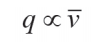
Thus, the heat flux q:

Where ![]() is the average cooling speed.
is the average cooling speed.
The cooling rate during the entire cooling process is measured and the minimum critical heat flux qcr2, the minimum heat flux at which the film breaks, is calculated. qcr1 is then determined.
By comparing the initial (maximum) heat flux qin of heat transfer from the workpiece surface to the outside after immersing the high-temperature workpiece in the medium, it can be inferred that two different cooling processes may occur in actual quenching cooling.
When qin < qcr1, the heat flow density of the workpiece heat transfer does not reach the critical heat flow density qcr1 required for the formation of the cooling medium vapor film, thus a stable vapor film cannot be formed. In this case, the vapor film stage is not observed. The workpiece directly enters the boiling stage and then transitions to the convection stage.
However, when qin ≥ qcr1, a vapor film can be formed on the surface after immersing the workpiece in the medium, resulting in a complete three-stage cooling process of vapor film stage, boiling stage, and convection stage.
This theory can also explain various steam film phenomena in engineering applications. For instance, increasing the surface roughness of the workpiece and reducing its size are equivalent to increasing the specific surface area of the workpiece and reducing its heat flow density, qin, thus eliminating (qin < qcr1) or shortening the steam film time (reaching qcr2 faster to cause the steam film to break).
Adding a certain amount of inorganic salts to the water increases the surface tension σ of the aqueous solution and also increases the density difference between the medium and steam, thereby increasing qcr1.
The double electric layer formed on the surface of the workpiece in the salt solution reduces the heat flow density qin of the workpiece, making it more challenging to form or accelerate the rupture of the vapor film under this dual effect.
This theory also provides insight into many quenching and cooling problems that cannot be explained by the “three-stage theory”. For example, low hardenability high carbon chromium steel in a medium is prone to reverse quenching, and the surface of the carburized layer is prone to non-martensite structure (ignoring alloy element depletion).
Based on the theory, an experiment was conducted to examine the impact of adding a refrigerant to the base oil on the steam film during quenching and cooling.
It is well-established that adding a refrigerant to the base oil can significantly reduce the duration of its vapor film, thereby enhancing the cooling capacity of the base oil and improving the uniformity of the workpiece quenching process.
In this study, the same concentration of refrigerant was dissolved in low viscosity and high viscosity base oils to simulate the cooling performance of fast quenching oil and isothermal quenching oil, respectively. The steam film during heating and cooling was observed through experiments.
The experiment used an 8mm diameter nickel chromium alloy probe, with a thermocouple temperature probe at its geometric center. A constant heating power of 2.7 kW was supplied by an induction coil with an inner diameter of 12.5mm. The temperature rise and drop process was recorded by a temperature recorder.
The test device is shown in Fig. 5.

Fig. 5 Induction heating and temperature recording device
Fig. 6 displays the time-temperature curve of the low viscosity base oil, fast oil, and isothermal oil during the heating process.
The heating rate temperature curve can be obtained by differentiating the curve.
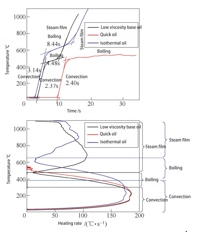
Fig. 6 Time temperature curve and heating rate temperature curve of heating process
As shown in the figure, except for fast oil, the probe has two noticeable inflection points on the temperature rise curves of the base oil and isothermal oil.
The increase in probe temperature reflects the net heat increase, which is the heat applied to the probe by induction heating minus the heat taken away from the probe surface by the quenching oil.
Since the material, size, and distance between the probe and coil remain constant, and the power of the heating coil remains unchanged, it can be assumed that the heat increase rate due to induction heating also remains constant.
In the initial low temperature stage, the medium has limited cooling capacity through convective heat transfer, resulting in a fast temperature rise rate of the probe.
After that, the medium begins to boil vigorously.
As the temperature continues to rise, the cooling capacity of the medium is greatly increased, causing a significant reduction in the temperature rise rate of the probe.
Later, a vapor film forms. At this time, the cooling capacity of the medium decreases again, causing the temperature rise rate of the probe to increase again.
Compared to fast oil and base oil, the duration of the convection stage and the transition temperature to boiling stage are mostly the same.
The addition of the refrigerant does not significantly alter the cooling capacity of the medium in the convection stage or the boiling point of the base oil.
However, under the heating power of 2.7 kW, the probe surface can no longer maintain a stable vapor film. This is because the addition of refrigerant increases the medium’s critical heat flux qcr2, making the vapor film more prone to cracking.
Additionally, the polymer film formed by the refrigerant on the probe surface reduces the thermal conductivity of the workpiece surface, decreasing the heat flow density of the workpiece, making qin < qcr1, leading to the failure of the vapor film formation.
The probe temperature was raised to 1000 ℃ through induction heating and then the heating was stopped.
The cooling process of the probe over time was recorded to obtain the well-known cooling time-temperature curve.
By differentiating the curve, the cooling rate-temperature curve during quenching can be obtained, as shown in Fig. 7.
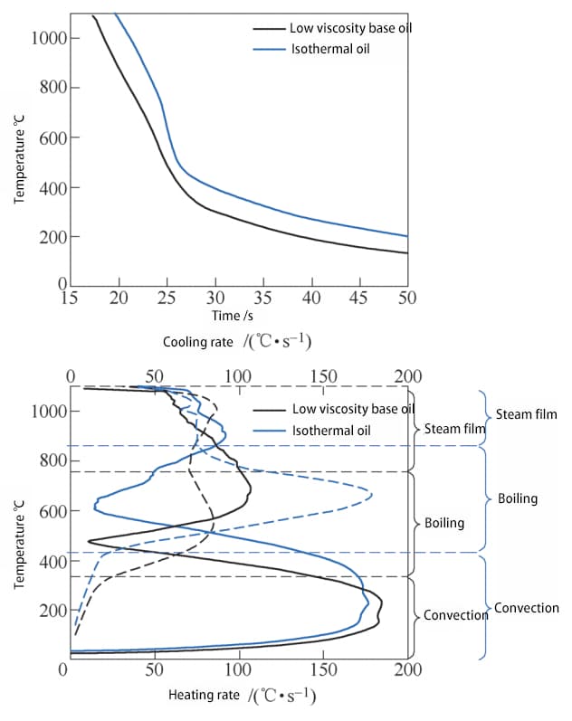
By superimposing the cooling rate-temperature curve with the heating rate temperature curve of the heating process (as shown in Fig. 7), it can be seen that the three stages of the quenching process are closely related to the temperature range of the three stages of the heating process.
However, compared to the heating process, the transition temperature between stages in the cooling process is slightly higher due to the following reasons:
In the heating process, induction heating starts from the surface and then transfers to the center of the probe, causing the measured center temperature to lag behind the surface temperature to some extent, resulting in a lower test temperature compared to the actual surface temperature.
In the cooling process, the core temperature also lags behind the surface temperature, resulting in a higher test temperature compared to the actual surface temperature.
At the same time, according to equation (4), the heat flow density in the cooling process is proportional to the average cooling speed:
Since the cooling rate of isothermal oil when the film breaks is lower than that of low viscosity base oil, it can be calculated that its critical heat flux qcr2 is also higher than that of low viscosity base oil. This means that the film can break at higher temperatures, which is in line with the observations made in engineering applications.
By analyzing the heat transfer process in the quenching process, it has become clear that the stages of steam film formation and the transition from steam film to nucleate boiling are much more complex than previously thought. The concept of critical heat flux, which is used in boiling heat transfer theory, has been introduced to explain the phenomenon of steam film in the quenching process.
Experiments were conducted using induction heating to observe and record the phenomena of boiling and steam film during heating and cooling. This combined approach aimed to gain a deeper understanding of the common phenomenon of steam film in quenching processes, which could provide more guidance for the design and development of new quenching cooling media with shorter steam film duration and faster cooling speed.
Theoretical discussions and experimental verification have shown that to reduce steam film in the quenching process and improve workpiece quenching uniformity, the following three aspects should be considered:
(1) Increase the critical heat flux qcr1 and qcr2 for the formation and rupture of the vapor film of the medium itself.
For example, increase the surface tension of the medium and the density difference between the gas and liquid phases, making the vapor film more difficult to form and easier to rupture.
(2) An additive that can form a film on the surface of the workpiece is introduced to attach to the surface of the workpiece to form a thermal insulation layer of moderate thickness, so as to reduce the heat transfer coefficient of the surface of the workpiece, thereby reducing the heat flow density qin of the surface of the workpiece, thereby reducing or even eliminating the steam film.
(3) Electrolyte is introduced to increase the critical heat flux qcr of the medium, and at the same time, a double electric layer is formed on the workpiece surface to reduce the heat flux qin of the workpiece surface, so as to reduce or even eliminate the vapor film.

As the founder of MachineMFG, I have dedicated over a decade of my career to the metalworking industry. My extensive experience has allowed me to become an expert in the fields of sheet metal fabrication, machining, mechanical engineering, and machine tools for metals. I am constantly thinking, reading, and writing about these subjects, constantly striving to stay at the forefront of my field. Let my knowledge and expertise be an asset to your business.