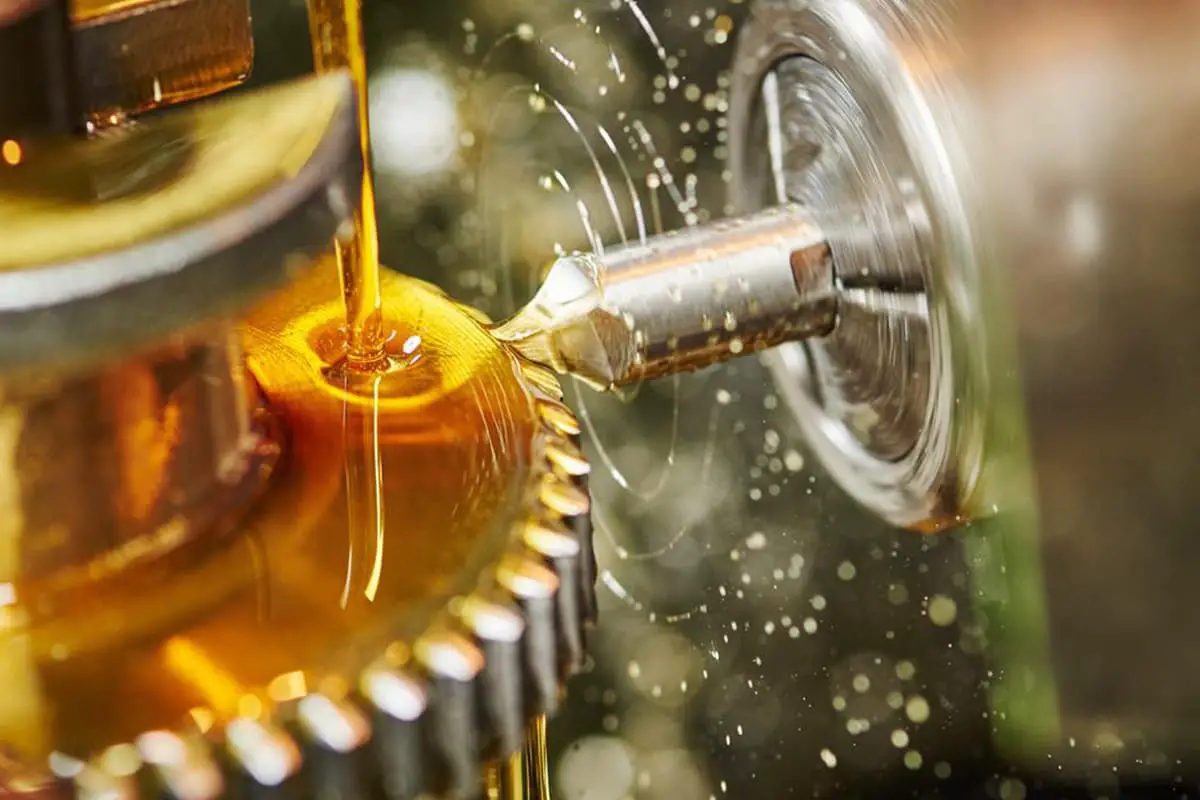
Imagine your car engine seizing up on a long drive or a factory machine grinding to a halt during peak production. At the heart of these issues lies a critical but often overlooked factor: friction and lubrication. This article delves into the mechanics of friction, the types of wear it causes, and how proper lubrication can prevent machinery breakdowns, enhance efficiency, and extend equipment lifespan. Discover essential tips for selecting and applying lubricants effectively, ensuring your machines run smoothly and reliably.
The purpose of mechanical lubrication is to reduce friction and wear between the contact surfaces of two relative moving parts, referred to as friction pairs.
Adequate lubrication can enhance mechanical efficiency, ensure long-term reliable operation of machinery, and conserve energy.
Machines with poor lubrication, at best, experience decreased power and increased wear; at worst, they can be damaged.
I. Concept of Friction and Lubrication
When two closely contacted objects move relative to each other along their contact surface, a resistance is generated that hinders this motion; this phenomenon is known as friction, and this resistance is called the friction force.
The ratio of the friction force to the vertical load is called the friction coefficient. The laws of friction can be described as follows:
1. Frictional force is proportional to the normal load: F∝W.
2. Frictional force is independent of surface contact, that is, unrelated to the size of the contact area.
3. Frictional force is not influenced by the magnitude of the surface sliding speed.
4. Static friction (when motion tends to occur) FS is greater than kinetic friction FK, i.e., Fs > FK.
Frictional Law Formula:
F = f · W or f = F/W
Where:
f — Frictional force;
W — Normal load, which is the load received by the contact surface.
In machinery, a connection comprising two parts that come into contact and move relative to each other is called a “kinematic pair” (also known as a “friction pair”), such as the slide and guide rail in machine tools; the ball and race in rolling bearings; the bearing shell and shaft diameter in sliding bearings, and so forth.
The operation of any machine relies on the relative motion of various kinematic pairs, and this relative movement inevitably results in friction.
Friction primarily causes unnecessary energy loss, and secondly, it produces heat, wear, and even failure on the interacting surfaces of the friction pairs.
Wear is the continuous loss of material from the surfaces of kinematic pairs. It leads to changes in the size and shape of these pairs, resulting in damage. For instance, as oil circulates within a bearing, the bearing hole surface and the shaft diameter gradually wear away.
This wear increases clearance, generates heat, and decreases the machine’s precision and efficiency. Along with it comes the generation of impact loads, increased frictional losses, and an accelerated rate of wear, ultimately leading to machine failure.
Lubrication involves applying a lubricant on the surfaces of parts moving relative to each other. This application separates the two surfaces in motion, ensuring that friction occurs not directly between the surfaces of the kinematic pair, but between the molecules within the lubricant.
Therefore, friction is the physical phenomenon that occurs when kinematic pairs move relative to each other, wear is a fact that accompanies friction, and lubrication is a critical measure to reduce both friction and wear.
II. Classification of Friction
There are several methods to categorize friction.
1. Classification Based on the State of Motion
Static Friction: This refers to the friction that occurs when one object tends to move relative to the surface of another. The resistive force in this case is known as static frictional force.
Static frictional force varies with the external force applied to the object. It is only when the external force overcomes the maximum static frictional force that the object begins to move noticeably.
Kinetic Friction: This is the friction that occurs when one object is moving relative to the surface of another. The tangential force that impedes the object’s motion in this situation is known as kinetic frictional force.
2. Classification Based on the Form of Contact
Sliding Friction: The friction that occurs when the contact surfaces slide relative to each other is called sliding friction.
Rolling Friction: The friction that arises when an object rolls along the contact surface under the action of torque is termed rolling friction.
3. Classification Based on the Lubrication State of the Surface
Dry Friction: Refers to friction where there is neither lubrication nor moisture.
Fluid Friction: This is the friction under fluid lubrication conditions. Here, the two surfaces are completely separated by a liquid oil film, and the friction manifests as a result of the viscous fluid.
Boundary Friction: This type of friction occurs when there’s a very thin layer of lubricant on the friction surface. In this case, friction does not depend on the viscosity of the lubricant but on the characteristics of the contact surface and the lubricant.
Mixed Friction: This refers to a transitional state of friction, including semi-dry and semi-fluid friction. Semi-dry friction is a situation where both boundary and dry friction occur. Semi-fluid friction is a condition where both fluid and dry friction occur.
In some oil refining and chemical equipment, the working conditions of the friction pairs can be complex, such as operating under high speed, high temperature, or harsh conditions like low temperature and vacuum. The friction and wear characteristics under these conditions have different unique features.
III. Causes of Friction
There are various explanations for the phenomenon of frictional force generated when contact surfaces move relative to each other. A comprehensive summary reveals the following points:
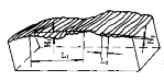
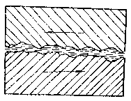
Parts of a machine that undergo relative motion are generally processed and possess smooth surfaces. However, in reality, no matter how precise the processing, the surface of a component can never be “absolutely” smooth. Under a microscope, it is always uneven, with high and low points, as depicted in Figure 1.
Figure 1
When the protrusions and indentations on the friction surface, under load and in close contact, interlock like the teeth of a cogwheel, collisions occur among these protrusions during the relative motion of the two contact surfaces, thus impeding their relative movement.
Furthermore, due to the load-bearing and close contact of the two friction surfaces, the surface is supported by several protrusions. The distance between the two surfaces at the support points is extremely small, within the range of molecular forces. When the surfaces move relative to each other, the protrusions must also move, which means overcoming the molecular forces at the supporting points.
Moreover, both the collision points and the support points endure extreme pressures, leading to severe deformation of the metal surfaces at these locations, causing the protrusions on one surface to embed into the other. Both collisions and plastic deformation result in localized instantaneous high temperatures, and tearing apart bonded points consumes energy.
The combined effect of all these factors manifests as friction.
IV. Wear
The phenomenon of continuous loss of material from the working surface of an object, due to relative surface motion, is referred to as wear.
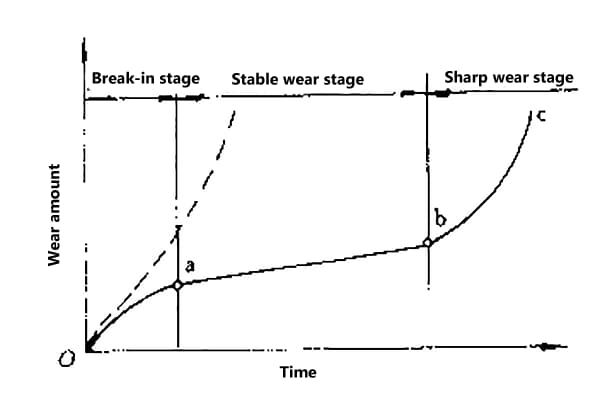
Figure 2
The wear process of mechanical parts during normal operation is generally divided into three stages, as shown in Figure 2.
(1) Break-in Stage (also known as the Running-in Stage): The new friction pair surface has a certain roughness, with a relatively small actual contact area. During the break-in stage, the surface gradually smooths out and the actual contact area progressively increases, slowing the wear rate, as indicated by the O-A segment in Figure 12-2. The slight wear during the break-in stage is intentionally used to set conditions for stable wear during normal operation.
By choosing a reasonable break-in procedure, selecting appropriate friction pair materials and machining processes, and using lubricating oil with active additives (break-in oil), the break-in period can be shortened. The oil should be changed once the break-in is complete.
(2) Stable Wear Stage: During this stage, wear occurs at a slow and steady rate, as shown by segment A-B in Figure 12-2. The slope of this segment indicates the wear rate, and the time on the x-axis represents the wear-resistant lifespan of the part.
(3) Severe Wear Stage: After point B in Figure 12-2, the wear rate increases sharply, leading to a decrease in mechanical efficiency, increased power and lubrication oil loss, loss of precision, abnormal noise and vibration, rapid increase in temperature of the friction pair, and ultimately, part failure. There are also times when the following situations occur:
ⅰ After the transition to the stable wear stage, the part experiences very minimal wear over a long period of time, with no obvious severe wear stage, resulting in a longer lifespan.
ⅱ There is no noticeable wear during the break-in and stable wear stages, but severe wear occurs when the surface layer reaches its fatigue limit.
ⅲ Under harsh wear conditions, the part transitions directly into the severe wear stage after the break-in stage, preventing the machine from operating normally.
Based on the wear’s destruction mechanism and the surface wear condition of the mechanical parts, wear can be broadly classified into several types.
1. Adhesive Wear
Adhesive wear refers to the phenomenon where material from one surface is transferred to another due to solid-phase adhesion during the relative motion of friction pairs. This can lead to severe seizing of the friction pairs.
2. Abrasive Wear
Abrasive wear is the phenomenon where hard particles or protrusions cause material loss during the friction process.
3. Surface Fatigue Wear
Surface fatigue wear occurs when two contact surfaces roll or slide in combination, causing material loss due to fatigue on the material surface under alternating contact pressure stress. Gear pairs, rolling bearings, rails and wheel hoops, and cam pairs can all produce surface fatigue wear.
Surface fatigue wear is classified into expansive and non-expansive types. Expansive surface fatigue wear can occur due to slightly poor plasticity of the material or improper lubrication selection when the alternating pressure stress is high.
4. Delamination Wear
The theory of delamination wear suggests that when two sliding surfaces come into contact, they transfer normal and tangential forces through the contact points. The micro-protrusions of the harder surface cause plastic deformation of the softer surface during sliding.
Repeated transfers of force and increasing plastic deformation of the surface cause voids to appear in the subsurface (10~100μm deep). Voids are likely to occur at the grain boundaries in metallography or at the interfaces of contained impurities. Under repeated forces, voids enlarge and connect with adjacent voids to form cracks.
Influenced by tangential forces, cracks develop in directions parallel to the surface. When cracks reach a certain length, they extend to the surface, ultimately causing the surface layer to peel off and form long, thin wear debris.
5. Electrical Erosion Wear
Electrical erosion wear primarily occurs on rotating electrified equipment. Due to the electrified status of the equipment, a potential difference exists between the shaft neck and the bearing.
This potential difference may lead to surface damage on the frictional surface for various reasons. Surface damage caused by electrical erosion wear typically manifests as dotted pitting.
6. Corrosive Wear (also known as Corrosive Mechanical Wear)
When friction occurs in a corrosive environment, a chemical reaction takes place on the frictional surface, generating reaction products.
Generally, these reaction products loosely adhere to the surface and are easily worn away in the subsequent friction process.
The newly exposed metal surface then generates additional reaction products. This cycle continues, gradually wearing down the metal surface. Corrosive wear requires both corrosion and friction to occur.
7. Fretting Wear
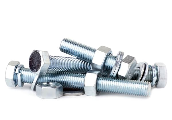
Fretting wear is caused by vibrational sliding with an amplitude range of 10-7 to 10-5mm, and it often occurs in the parts at mechanical joints (such as bolts, splines, etc.). These parts wear due to vibrational loads.
8. Erosion
Erosion refers to the damage sustained by an object’s surface upon impact with a particle-laden fluid.
Erosion is a prominent issue for components operating at high speeds, for example, the carbon fiber-reinforced plastic turbine blades that are highly dense and strong. It is required that the leading edge of the blade has high erosion resistance.
V. Lubrication
Lubricating oil (agent) is introduced between the contact surfaces of various friction pairs that undergo relative motion.
This forms a lubrication film between the two friction surfaces, separating the original direct contact dry friction surfaces and converting dry friction into friction among the lubricating oil (agent) molecules.
This achieves reduced friction, decreased wear, and extended lifespan of mechanical equipment – this is lubrication.
1. Lubrication Requirements
The requirements for lubrication vary with the function, working conditions, and the nature of each friction pair. Summing up, the following points are considered:
(1) Select the appropriate lubricating oil depending on the working conditions and functional nature of the friction pair.
(2) Determine the correct lubrication method and approach based on the working conditions and functional nature of the friction pair, and distribute the lubricating oil to each friction surface in a defined manner.
(3) Maintain good lubrication management.
2. The Role of Lubrication Oil
The purpose of using lubrication oil is to lubricate the frictional parts of machinery, reducing friction resistance, preventing seizure and wear, and minimizing energy consumption to enhance mechanical efficiency. Beyond this, there are other practical benefits, summarized as follows:
(1) Reducing friction. Introducing lubrication oil between frictional surfaces can lower the coefficient of friction, thereby reducing frictional resistance and conserving energy consumption. The viscosity and film thickness of lubrication oil play a crucial role in minimizing friction under fluid lubrication conditions. The chemical properties and activity of lubrication oil (additives) become extremely important when boundary lubrication conditions arise due to an increase in metal-to-metal contact points on the frictional interface.
(2) Reducing adhesive wear of mechanical parts. Surface fatigue wear and corrosion wear are closely related to lubrication conditions. The inclusion of antioxidants and anticorrosive agents in lubricants can help suppress corrosion wear, while the addition of oiliness and pressure resistance agents can effectively reduce adhesive wear and surface fatigue wear.
(3) Cooling effect. Lubricating oil can alleviate friction and absorb, conduct, and dissipate heat, thus reducing the temperature elevation caused by mechanical operation friction.
(4) Anticorrosion effect. When a friction surface is covered with a lubricant, it can prevent or avoid corrosion and rust caused by air, water droplets, steam, corrosive gases and liquids, dust, oxides, etc. The anticorrosive ability of lubricating oil is directly related to the thickness of the oil film retained on the metal surface and also depends on the composition of the lubricant. Using certain surfactants as rust inhibitors can enhance the rust-resistance of the lubricant.
(5) Insulation properties. The electrical resistance of refined mineral oil is high, such as the electrical resistance of electric insulating oil used as an electrical insulating material is 2×10¹⁶Ω/mm² (water is 0.5×10⁶Ω/mm²).
(6) Force transmission. Oil can serve as a medium for transmitting static force, such as hydraulic oil in car cranes. It can also act as a medium for transmitting power, such as automatic transmission fluid.
(7) Vibration reduction. Lubricating oil absorbed on the metal surface has low inherent stress, thus it has the ability to absorb shock when the friction pair is subjected to impact load. For example, car shock absorbers use fluid damping (converting mechanical energy into fluid energy).
(8) Cleaning effect. Lubrication oil (grease) forms a seal on certain exposed parts, preventing the intrusion of moisture or debris.
3. Various Lubrication States
According to the lubrication state on the friction pair surface, lubrication types can be divided into: fluid lubrication, boundary lubrication, and mixed lubrication, as shown in Figure 3.
Figure 3
(1) Fluid lubrication.
Liquid lubricant is applied between two friction surfaces, the lubricating oil completely separates the two friction surfaces, transforming metal-to-metal dry friction into internal friction within the liquid. This is fluid lubrication (see Figure 4).
The advantage of fluid lubrication is that the internal friction force of the liquid lubricant is small, typically ranging from 0.001 to 0.01, only a thousandth of that of direct metal-to-metal contact. The conditions for achieving fluid lubrication are:
Figure 4
(a) There must be relative motion between the frictional surfaces.
(b) In the direction of surface movement, the oil layer must form a wedge.
(c) The lubricating oil must have a certain adhesive force with the frictional surface. This is related to the oil’s properties. When the lubricating oil moves with the frictional surface, it must have a certain internal frictional force, or in other words, it must have a certain viscosity.
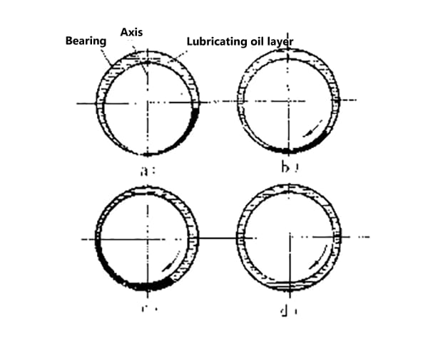
Figure 5
Using a sliding bearing to form fluid lubrication as an example, as shown in Figure 5. When the shaft is not rotating (Figure 5a), the lubricating oil on the contact surface of the shaft and the bearing is completely squeezed out. As the shaft begins to rotate in the direction of the arrow (see Figure 5b), due to the adhesive force between the shaft surface and the shaft, and the internal friction in the oil layer, the entire wedge-shaped oil layer in the lower right of the bearing is moved forward with the shaft, as if a wooden wedge is inserted into a narrow gap to force the gap open, forcing the shaft to lift up and slightly deviate to the left.
As the rotational speed of the shaft increases, the position of the shaft also raises further, and the eccentricity decreases (as in Figure 5c). When the rotational speed of the shaft is infinitely large, the centers of the shaft and the bearing should coincide (add Figure 5d).
The thickness of the oil layer between the friction surfaces of the shaft and the bearing is determined by the load carried by the shaft and the size of the internal friction of the oil layer. The size of the internal friction of the oil layer depends on the viscosity of the oil and the relative motion speed of the shaft and the bearing.
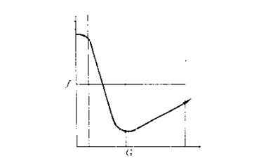
It can be represented by the bearing characteristic factor G:
G = η·N/P
Where: η is the viscosity of the lubricating oil;
N is the bearing speed (P·s);
P is the load on the projected area of the shaft (N/m2).
The direct relationship between the G value and the thickness of the lubricating oil, a smaller G value results in a thinner oil layer, and vice versa, a thicker oil layer is formed. Therefore, through the G value, it can be determined whether a sufficiently thick oil layer can be formed to ensure fluid lubrication.
However, it should be noted that because the types of lubricated components, geometric configurations, and machining accuracy are all different, there is no minimum G value to guarantee fluid lubrication. Generally speaking, when the sliding speed is high and the load is light, oil with a smaller viscosity should be chosen; when the sliding speed is low and the load is heavy, oil with a larger viscosity should be selected.
(2) Boundary Lubrication
Fluid lubrication is ideal, yet apart from bearings and guideways with relatively low contact pressure intensities, achieving fluid lubrication is challenging.
When mechanical operation is at an exceedingly low speed (for instance, checking motion speed at 0.1cm/s) and the friction surface load is substantial, even using highly viscous lubricating oil, it is difficult to generate a G value sufficient to form a complete oil layer between the friction surfaces, necessary for ensuring the level of fluid lubrication.
At such times, even if the fluid lubrication film is damaged, there remains a very thin (about 0.01μm) oil film on the contact surface. This thin layer of oil has a unique bonding force with the friction surface, forming a “film” that continues to protect the friction surface to a certain extent.
This lubrication state is referred to as boundary lubrication (as shown in Figure 6), and the film formed is called a boundary film. Because the thickness of the boundary film is minimal, the surface texture properties of the friction surface can significantly influence the lubrication conditions.
Figure 6
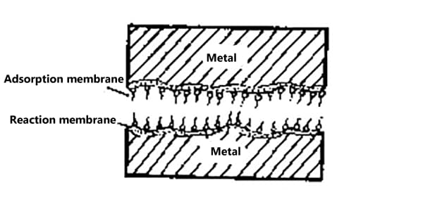
Based on differing structural forms, boundary films can be categorized into two types: adsorption films and reaction films.
Adsorption films are formed by the adsorption of polar molecules of the lubricant on the friction surface, while reaction films are generated through the chemical reaction of additives, such as sulfur, phosphorus, and chlorine in the lubricant, with the friction surface.
If the load is extremely high, overcompression at the friction surface’s peak points can lead to the rupture of the adsorption film, resulting in direct metal-to-metal contact and causing dry friction.
Figure 7
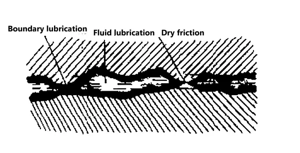
(3) Semi-fluid Lubrication (Mixed Lubrication)
The lubrication film formed on the friction surface is locally damaged, causing the oil to be uneven and discontinuous. This results in simultaneous occurrences of liquid lubrication, boundary lubrication, and under-lubrication on the friction surface, referred to as semi-fluid lubrication, as shown in Figure 7.
The primary causes of semi-fluid lubrication include excessive loads, frequent changes in speed and load, improper selection of lubricants, and rough friction surfaces.
The aforementioned three states of lubrication often interchange during machine operation, rarely existing independently; there is merely a distinction of primary and secondary states. These conditions shift with changes in oil volume, oil properties, and other factors.
Therefore, one typically strives to improve lubrication conditions by increasing oil supply and pressure, enhancing oil properties, and selecting appropriate viscosity.
VI. Classification of Lubricating Oils
Lubricating oils can be categorized into various types based on different usage requirements. According to the GB498-87 General Classification of Petroleum Products and Lubricants, petroleum products and lubricants are divided into six main categories. The principle of classification is based on the major characteristics of petroleum products.
The category names are determined by a prefix letter of the English name that reflects the main characteristics of each type of product, with lubricants and related products designated as the “L” class. Owing to the vast variety and widespread applications of lubricants and related products, categorizing all as “L” class based on the general classification of petroleum products can lead to numerous inconveniences.
Therefore, the products within the “L” class are further divided into 19 groups according to their main application scenarios. Each group has a separate classification standard. The detailed classification of a group is determined by the type of product, but the type must meet the main application scenario required by the group. The grouping of “L” class products is shown in Table 1.
Table 1:
Category
Application Scenario
Category
Application Scenario
A
Total Loss System
P
Pneumatic Tools
B
Demolding
Q
Thermal Conduction
C
Gears
R
Temporary Corrosion Protection
D
Compressors (including refrigerators and vacuum pumps)
As the founder of MachineMFG, I have dedicated over a decade of my career to the metalworking industry. My extensive experience has allowed me to become an expert in the fields of sheet metal fabrication, machining, mechanical engineering, and machine tools for metals. I am constantly thinking, reading, and writing about these subjects, constantly striving to stay at the forefront of my field. Let my knowledge and expertise be an asset to your business.
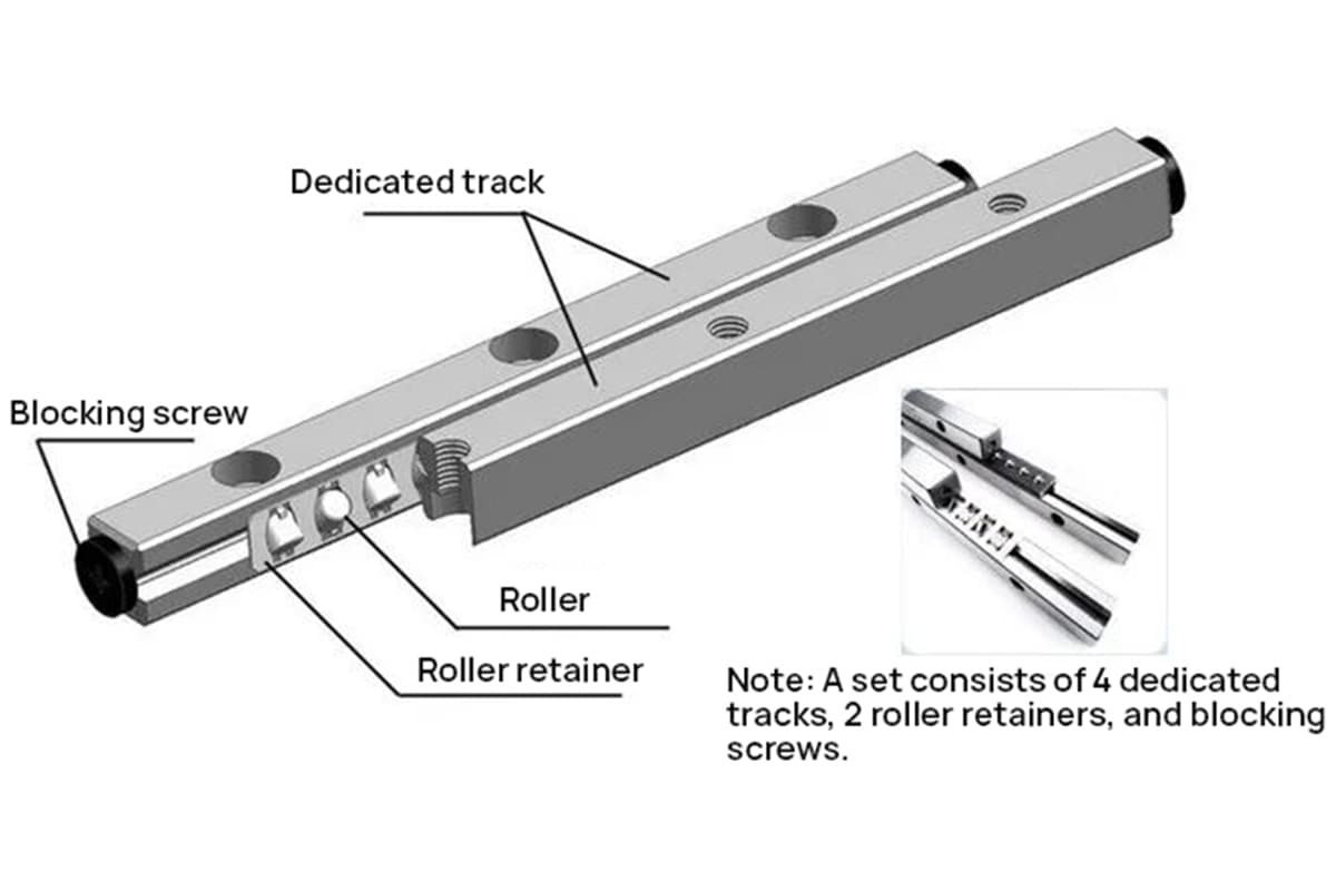
Imagine a component so precise it revolutionizes how machines move with exactness and stability. Crossed roller guides are that innovation, providing unmatched accuracy and low friction, making them ideal for…
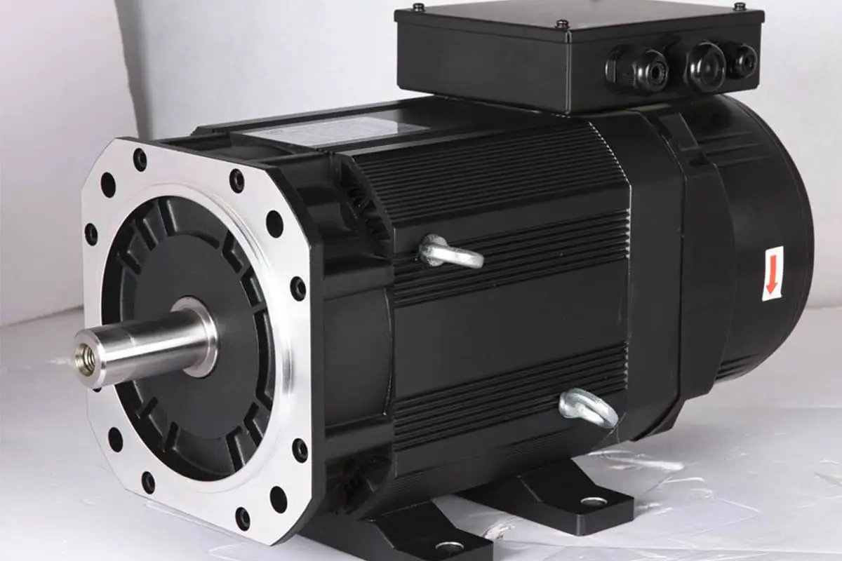
Ever wondered how machines select the perfect motor? This article unveils the fascinating process behind choosing the right servo motor for various mechanical tasks. Dive in to understand the calculations…
Why do bearings heat up during operation, and how can we estimate this heat? This article explores the external and internal factors contributing to bearing temperature rise, such as friction…
Have you ever wondered how mechanical structures transform ideas into tangible designs? Mechanical structure design turns abstract principles into detailed schematics, ensuring every part is optimized for functionality, strength, and…
Imagine a world where machines can see, feel, and respond to their surroundings with unparalleled precision. This is the promise of novel sensing technologies in mechanical engineering. By integrating advanced…
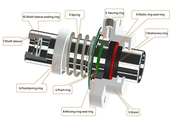
Have you ever wondered how crucial mechanical seals are in preventing leaks and ensuring the smooth operation of machinery? In this blog post, we'll dive into the world of mechanical…
What kind of questions can help you ace a mechanical engineering interview? This article dives into the top 20 questions that test various aspects of mechanical engineering, from transmission systems…
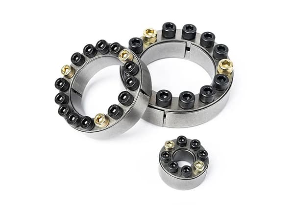
Have you ever struggled to choose between hydraulic and mechanical expansion sleeves for your machinery? This article dives into their key differences, exploring the benefits and drawbacks of each. From…
What role does friction play in the stability of bolted connections? In the world of high-strength bolted assemblies, especially for critical components like crane slewing rings, understanding the impact of…