Welding Flux: How to Select and Use Correctly
What if selecting the right welding flux could be the key to flawless joints and efficient projects? This article explores the various types of welding fluxes, their roles in enhancing…
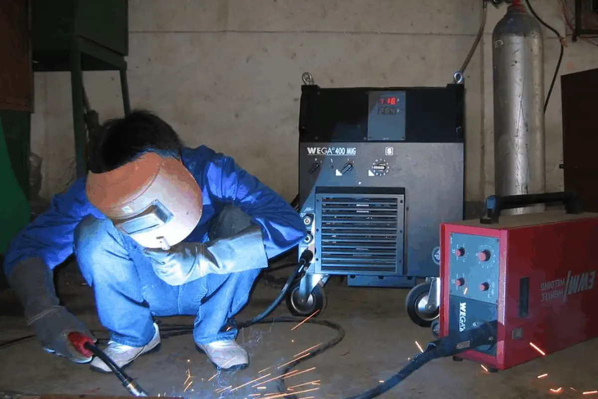
Choosing the right arc welding power source can be a game-changer for any welding project. Have you ever wondered how to pick the most efficient power source for your specific needs? This article dives into the critical factors for selecting the optimal arc welding power source, comparing AC and DC options, and outlining their performance and economic considerations. By reading further, you’ll gain insights on improving welding quality, enhancing safety, and optimizing energy use, ensuring your welding projects are both efficient and cost-effective.
The selection of the arc welding power source is a critical part in determining the electrical performance of the welding equipment (welder). Although arc welding power sources have some degree of universality, different types of arc welding power sources vary in structure, electrical performance, and main technical parameters.
As shown in Tables 1 and 2, there are significant differences in the characteristics and economy between AC arc welding power sources and DC arc welding power sources. Therefore, only reasonable selection can ensure the smooth progress of the welding process, which is both economical and achieves good welding results.

Generally, the arc welding power source should be selected based on the following aspects:
Table 1: Comparison of Characteristics of AC and DC Arc Welding Power Sources.
| Item | Alternating current | Direct current |
| Arc stability | low | high |
| Polarity interchangeability | nothing | have |
| Influence of magnetic bias | tiny | more |
| No-load voltage | higher | Lower |
| Electric shock hazard | larger | lesser |
| Construction and maintenance | Simpler | More complex |
| Noise | not big | Large generator, small rectifier and smaller inverter |
| Cost | low | high |
| Power supply | General single-phase | General three-phase |
| Weight | lighter | Heavier, lightest inverter |
Table 2: Comparison of Economy of AC and DC Arc Welding Power Sources.
| Main indicators | DC arc welding alternator | AC arc welding generator | Arc welding rectifier | arc welding inverter |
| Electric energy consumption per kilogram of welded metal | 6~8kW.h | 3~4 kW.h | 2. | |
| 0.3~0.6 | 0.65~0.90 | 0.6~0.75 | 0.8~0.9 | |
| 0.6~0.7 | 0.3~0.6 | 0.65~0.70 | 0.85~0.99 | |
| Power factor at no-load | 0.4~0.5 | 0.1~0.2 | 0.30~0.4~ | 0.68~0.86 |
| no-load power consumption | 2~3kW | 0.2 kW | 0.38~0.46 kW | 0.03~0.1 kW |
| Manufacturing material consumption | 100% | 30~35% | 35~40% | 8~13% |
| Man-hours for production of arc welding power source | 100% | 20~30% | ||
| Price | 100% | 30~40% | ||
| Area occupied by each unit | 0.5~0.7m2 | 0.2~0.3m2 | 0.4~0.9m2 | 0.11~0.13m2 |
There are three basic types of welding current: DC, AC, and pulse, and corresponding arc welding power sources are available: DC arc welding power source, AC arc welding power source, and pulse arc welding power source.
In addition, there is also the option of arc welding inverters. We should choose the type of arc welding power source reasonably according to technical requirements, economic effects, and working conditions.
(1) Manual arc welding:
Acidic electrodes are used to weld general metal structures, and dynamic iron-core, dynamic coil, or tap-changer arc welding transformers (such as BXl-300, BX3-300-1, BX6-120-1, etc.) can be used.
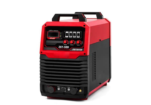
Alkaline electrodes are used to weld more important structural steel, and DC arc welding power sources, such as arc welding rectifiers (such as ZXG-400, ZXl-250, ZX5-250, ZX5-400, ZX7-400, etc.), can be used. These arc welding power sources should all have a descending characteristic.
(2) Submerged arc welding:
A larger capacity arc welding transformer is generally selected. If higher product quality is required, arc welding rectifiers or rectangular wave AC arc welding power sources should be used. These arc welding power sources should generally have a descending external characteristic.
For constant speed wire feeding, a smoother descending characteristic is preferred, and for variable speed wire feeding, a steeper descending characteristic is preferred.
(3) Tungsten Inert Gas Welding (TIG Welding):
TIG welding requires an arc welding power source with constant current characteristics, such as an arc welding inverter or arc welding rectifier. For welding aluminum and its alloys, an AC arc welding power source is preferred, preferably a rectangular wave AC arc welding power source.
(4) CO2 Gas Shielded Welding and Melting Electrode Inert Gas Welding:
In these cases, arc welding rectifiers and arc welding inverters with flat characteristics (for constant speed wire feeding) or descending characteristics (for variable speed wire feeding) can be used. For high-quality TIG welding, a pulse arc welding power source must be used.
(5) Plasma Arc Welding:
An arc welding rectifier or arc welding inverter with constant current characteristics is preferred. If using melting electrode plasma arc welding, select an arc welding power source according to the requirements of melting electrode inert gas welding.
(6) Pulse Arc Welding:
Pulse plasma arc welding and pulse TIG welding should use a pulse arc welding power source. In high-demand situations, arc welding inverters or transistor pulse arc welding power sources are preferred.
As can be seen from the above, a welding process method does not necessarily have to use a particular type of arc welding power source. However, the selected arc welding power source must meet the electrical performance requirements of that welding process method.
This includes external characteristics, regulation performance, no-load voltage, and dynamic characteristics. If some electrical performance cannot meet the requirements, it can also be achieved through modification, which just shows that arc welding power sources have a certain degree of universality.
(1) Roughly determining the power of the arc welding power supply
The main specification for welding is the welding current. For simplicity, the capacity can be selected based on the required welding current by referring to the number behind the arc welding power supply model. For example, the number “300” in BXl-300 represents the rated current of the power supply is 300A.
(2) Allowable welding current under different load duration rates
As discussed in Chapter 2, the maximum output current of an arc welding power supply is mainly determined by its allowable temperature rise.
Therefore, when determining the allowable welding current, the load duration rate should be considered. Under the rated load duration rate, the arc welding power supply will not exceed its allowable temperature rise when working at the rated welding current.
When the load duration rate changes, the maximum current that the arc welding power supply can use without exceeding its allowable temperature rise can be converted based on the principle of equal heat generation and achieving the same rated temperature.
Under normal production conditions, single-station arc welding power sources should be used as much as possible. However, in large welding workshops such as shipbuilding workshops, where there are many welding stations and they are concentrated, multi-station arc welding power sources can be used.
Since DC arc welding power sources require a resistor box for current sharing, which consumes a lot of power, they should be used as little as possible.
In maintenance welding work, where the weld length is not long and the continuous use time of the power source is short, arc welding power sources with a lower rated load continuous rate can be selected, such as those with a continuous rate of 40%, 25%, or even 15%.
As arc welding power sources consume a lot of power, for energy-saving purposes, high-efficiency and energy-saving arc welding power sources should be selected as much as possible, such as arc welding inverters, followed by arc welding rectifiers and transformers. Unless specifically required, DC arc welding generators do not need to be used.
Taking the most widely used manual arc welding power source as an example, this section will introduce the knowledge of installing an arc welding power source. The schematic diagram of the main circuit of the manual arc welding machine is shown in Figure 8-1.

As can be seen from the diagram, in the main circuit, in addition to the arc welding power source, there are also accessories such as cables, fuses, switches, etc. Therefore, the selection of relevant accessories should be discussed first.
(1) Selection of Cables
Cables include power lines from the grid to the welding power source, and welding cables from the welding power source to the welding torch and workpiece. When selecting power cables, the following factors should be considered:
When selecting welding cables, wear resistance, ability to withstand mechanical forces, and flexibility for movement should be considered. The cross-sectional area of the welding cable can be selected according to Table 8-1 based on the current and cable length. Different types and models of power lines and welding cables can be selected according to the purpose and Table 8-1.
(2) Selection of Fuses
Common fuses include tube-type, plug-in, and spiral fuses. The rated current of the fuse should be greater than or equal to that of the fuse.
For arc welding transformers, rectifiers, and inverters, as long as the rated current of the fuse is slightly higher than or equal to the rated primary current of the welding power source, it is sufficient. For DC arc welding generators, since the starting current of the motor is very large, the fuse cannot be selected according to the rated current of the motor but should be chosen based on the following formula:
Rated current of fuse = (1.5~2.5) x Rated current of motor If there is a starter, the coefficient in the above formula should be 1.5.
(3) Selection of Switches
Common switches include knife switches and iron shell switches.
The rated current of the switch for arc welding transformers, rectifiers, inverters, transistorized arc welding power sources, and rectangular wave AC arc welding power sources should be greater than or equal to the rated current. The rated current of the switch for arc welding generators is three times the rated current of the motor.
(1) Arc Welding Rectifiers, Inverters, and Transistorized Arc Welding Power Supplies
a. For new power supplies that have not been used for a long time, insulation must be checked before installation, which can be done by using a 500V megohmmeter. Before testing, however, the rectifier or silicon rectifying element and the high-power transistor group should be short-circuited with wires to prevent the silicon element or transistor from being breakdown by overvoltage.
The insulation resistance between the welding circuit and the secondary winding to the casing should be greater than 2.5M. The insulation resistance between the rectifier and the primary and secondary winding to the casing should not be less than 2.5M.
The insulation resistance between the primary and secondary windings should not be less than 5M. The insulation resistance between the control circuit that is not connected to the primary and secondary circuits and the chassis or other circuits should not be less than 2.5M.
b. Check whether there is any damage or loose connection inside the power supply due to transportation before installation.
a. Check whether the power supply capacity of the grid is in line with the rated capacity of the arc welding power supply, and whether the selection of switches, fuses, and cables is correct and whether the insulation of the cables is good.
b. The wire section and length of the power line and the welding cable line should be appropriate to ensure that the voltage drop of the power line does not exceed 5% of the grid voltage and the total voltage drop of the welding circuit cable line does not exceed 4V under the rated load.
(2) Arc Welding Transformers
When wiring, pay attention to the primary voltage value marked on the factory nameplate. The primary voltage can be 380V, 220V or dual-use. When installing multiple units, they should be connected to the three-phase power grid separately to achieve as much balance of the three-phase load as possible. Other matters are the same as for arc welding rectifiers.
(3) DC Arc Welding Generators
In addition to the above-mentioned matters, the following should also be noted:
The correct use and maintenance of arc welding power sources not only ensures their normal working performance but also prolongs their service life.
Common sense for use and maintenance
(1) Before use, the arc welding power source must be inspected in accordance with the product manual or relevant national standards, and a certain knowledge base should be established to ensure correct usage.
(2) Prior to welding, check whether all connections are correct, especially whether the welding cable joint is tightened to prevent overheating or burning.
(3) Do not move or open the top cover of the machine when it is connected to the power grid or during welding.
(4) When running without load, first check whether the sound is normal, and then inspect whether the cooling fan is blowing normally and whether the rotation direction is correct.
(5) The machine should be kept clean, and dust should be blown off regularly with compressed air. Regular electric testing, inspection, and maintenance are also necessary.
(6) Necessary strict management and usage systems should be established.
Parallel use of arc welding power sources:
When the welding current of one arc welding power source is insufficient, multiple arc welding power sources can be connected in parallel for use. However, it is important to ensure balanced current, polarity, and other related issues.
Arc welding power sources have certain versatility. However, when their versatility cannot meet certain welding process requirements, similar performance arc welding power sources that can be easily modified can be selected and modified for use.
Arc welding rectifiers can also be easily modified to have the desired performance. For example, magnetic amplifier-type arc welding rectifiers used for manual arc welding have a descending external characteristic.
To use them for CO2 gas shielded welding with fine wire and constant speed feeding, it is only necessary to remove or increase the resistance of the three internal bridge resistors of the magnetic amplifier to make it a fine wire CO2 arc welding power source with a flat characteristic or slow descending characteristic.
If it is needed to use it as a pulse arc welding power source, it can be modified by changing the magnetic amplifier to an impedance imbalance, or reducing the voltage of a certain phase, or changing the constant excitation current to a pulsed excitation current.
When necessary, arc welding generators can also be modified. For example, by removing the demagnetizing winding of the AXl-500 and changing the parallel excitation winding to a series excitation winding, the descending characteristic can be changed to a flat characteristic, and so on.
To save electricity, it is best to replace DC arc welding generators with silicon arc welding rectifiers or thyristor arc welding rectifiers. With the improvement of the development and production level of arc welding inverters, their reliability and performance have reached the level of traditional arc welding power sources, such as thyristor-type, and even top-notch foreign arc welding power sources.
In addition, they have good dynamic characteristics and welding process, save electricity and materials, and are affordable. They should be widely promoted and used.
As we all know, arc welding transformers are transformers with high leakage inductance or large reactance. The power factor is as low as about 0.4~0.6, so it is necessary to improve the power factor to reduce the supply of reactive power to the grid and improve the power quality.
There are two ways to install capacitors to compensate for the power factor:
(1) Factories that use arc welding power sources extensively, such as shipyards, metal structure factories, bridge manufacturing factories, etc., can adopt centralized compensation.
(2) For rural and small enterprises that do not have centralized compensation conditions, capacitors can be installed on the arc welding transformers for compensation, as shown in Figure 3-1.

Installing “energy-saving devices” on arc welding transformers not only has a certain effect on reducing no-load power loss but also can effectively prevent electric shock.
Therefore, it can also be called “electric shock prevention and energy-saving device.” Such products are available both domestically and internationally.
Arc welding power supply is an electrical equipment that can easily cause equipment and personal accidents if necessary safety measures are not taken or if precautions are not taken. This can lead to irreparable losses, so it should be avoided as much as possible.
The no-load voltage of a manual arc welding power source is generally between 60-90V, and welders often operate in high humidity environments, which increases the risk of electric shock. The danger is especially greater during welding in high places and inside metal containers. An electric current flowing through the heart of a human body can be life-threatening if it reaches a few milliamperes. The following methods can be used to avoid electric shock:
(1) Avoid contact with live parts:
(2) Limit the voltage that people can come into contact with: Sometimes it is difficult to avoid coming into contact with certain live objects, so it is necessary to limit the voltage of these live objects to ensure safety. For example, the maximum allowable value for the no-load voltage of an arc welding power source is specified; the AC voltage of the control circuit should not be greater than 36V, and the DC voltage should not be greater than 48V; the voltage of the work light should not be greater than 12V.
(3) Increase the insulation resistance: The human body’s resistance is mainly in the skin, and the resistance value is related to whether the skin is dry or not. In summer, sweating reduces the human body’s resistance, which increases the risk of electric shock. In addition, the human body’s resistance is also related to health status, mental state, and emotional state. There are many ways to increase the insulation resistance, such as wearing rubber gloves when contacting high voltage; wearing leather gloves when performing manual arc welding; wearing rubber shoes when working outdoors on rainy days; sitting on a wooden stool when working; and wearing a rubber cap when working inside a metal container.
(4) Ground or zero the machine casing: Under normal circumstances, the machine casing is not live. However, the insulation between the live parts inside the arc welding power source and the machine casing may be broken down, causing the machine casing to become live due to contact. The following measures should be taken to ensure personal safety:
The automatic voltage reduction device is actually a “power-saving device” mentioned earlier. There are many types of these devices, and Figure 4 shows an example.

Arc welding transformers are usually adjusted by hand directly on the transformer box to adjust the welding current. When the workpiece is far away from the arc welding transformer, this adjustment method becomes inconvenient.
Therefore, remote control can be used, which can be achieved by an electric motor, gearbox, and relevant remote control circuit. The welder carries an adjusting rod with them and uses the welding tongs to hold the adjusting rod at the work site to control the forward and reverse rotation of the electric motor, thereby transmitting the current adjustment mechanism and changing the welding current. This remote control device is not only easy to operate but also has anti-electric shock and power-saving features, which can achieve the goal of safe work and energy saving.
(1) Principle of Anti-Electric Shock and Power-Saving
When the control transformer T2 is turned on, V1 is cut off, V2 is saturated and conducts, V3 is cut off, and relay K3 is not energized. The normally open contact K3-2 prevents the AC contactor KM1 and KM2 from being energized. At this time, the arc welding transformer T1 is not connected to the 380V power grid and is in a safe, power-saving non-working state.
(2) Principle of Remote Control Adjustment of Welding Current
When the adjusting rod is placed between the welding tongs and the workpiece, if the diode in the adjusting rod is pointed towards the workpiece, a DC voltage of “negative on the bottom and positive on the top” is generated on R25 by rectifying the 24V AC voltage through the diode.
This voltage generates a current in the circuit of VD18->R20->Emitter junction of V5->VD19->R25, causing V5 to saturate and conduct. K2 is then energized, and contact K2-2 closes, causing the electric motor M to rotate forward, and the dynamic iron core (or winding) of the arc welding transformer T1 moves outward or downward to increase the welding current. Conversely, if the diode in the adjusting rod is pointed towards the welding tongs, V4 conducts, K1 is energized, and contact K1-1 closes, causing M to rotate backward and decrease the welding current.

Due to the good dynamic characteristics of inverter arc welders, a relatively low no-load voltage is required. Moreover, the voltage can be easily reduced to the desired value through simple methods without significantly affecting the arc striking performance.

As the founder of MachineMFG, I have dedicated over a decade of my career to the metalworking industry. My extensive experience has allowed me to become an expert in the fields of sheet metal fabrication, machining, mechanical engineering, and machine tools for metals. I am constantly thinking, reading, and writing about these subjects, constantly striving to stay at the forefront of my field. Let my knowledge and expertise be an asset to your business.