How Do Welding Parameters and Processes Affect the Weld Seam?
How do welding parameters impact the quality of a weld seam? Whether it’s the current, arc voltage, or welding speed, each factor plays a crucial role. Curious how these elements…
Have you ever wondered how thin sheet metal is flawlessly joined in complex machinery? This article explores the fascinating world of welding techniques, from manual arc welding to MIG and TIG methods. You’ll uncover practical tips and expert advice to enhance your welding skills and ensure top-notch results. Get ready to transform your understanding of metal fabrication!
Arabic numeral codes are used to represent various metal welding methods. These numerical codes can be used on the diagram as a symbol for the welding method and should be marked at the end of the guide line.
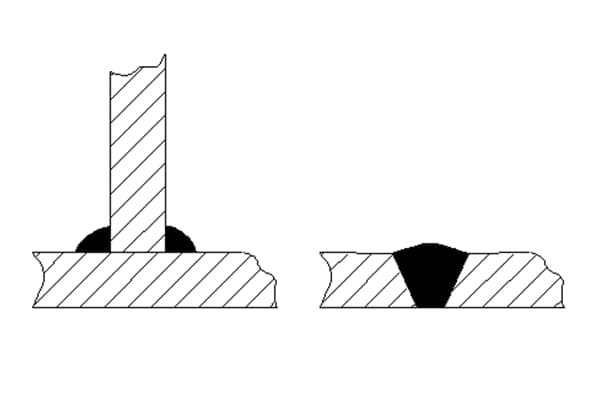
For example, the following welding symbol indicates that a fillet weld is made by manual electric arc welding.

(The ![]() indicates a fillet weld, and the Arabic numeral 111 at the end of the reference line indicates that manual electric arc welding is used.)
indicates a fillet weld, and the Arabic numeral 111 at the end of the reference line indicates that manual electric arc welding is used.)
| Code | Welding method |
| 111 | Manual arc welding (coated electrode consumable electrode arc welding) |
| 131 | MIG welding (consumable argon arc welding) |
| 135 | Carbon dioxide gas shielded welding |
| 141 | TIG welding (tungsten argon arc welding) |
| 311 | Oxygen acetylene welding |
| 21 | spot welding |
| 782 | Stud resistance welding (seed welding) |
The numerical codes in the table represent the welding methods commonly used in thin sheet metal welding.
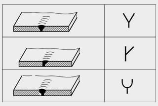
| Welding form | Docking | Corner joint T-joint | Lapping | ||
| Basic symbols |  Curled edge weld Curled edge weld |  Type I weld Type I weld |  Fillet weld Fillet weld |  Plug or slot welding Plug or slot welding |  Spot weld Spot weld |
Manual arc welding uses coated (flux-coated) welding rods and workpieces as electrodes, using the high heat (6000-7000 ℃) generated by the arc discharge to melt the welding rod and the workpiece, making them into one body.
The welding rod is operated manually. It is flexible, maneuverable, and widely applicable, and can be welded in all positions. The equipment used is simple, durable, and inexpensive. The quality of the weld depends on the operator’s technical level.
Welding specification for manual arc welding refers to the diameter of the welding rod, the current intensity of the welding, the arc voltage, and the type of power supply (AC or DC). In DC manual arc welding, it also includes the selection of polarity.
2.1.1 Diameter of the welding rod
The diameter of the welding rod has a significant impact on the welding quality and is closely related to improving productivity.
Using a welding rod that is too thick will cause incomplete penetration and poor weld formation; using a welding rod that is too thin will reduce productivity. The main basis for selecting the diameter of the welding rod is the thickness of the welded part and the welding position.
Recommended diameter values based on the thickness of the welded part are as follows (mm):
| Weldment thickness | 0.5-1.0 | 1.5-2.0 | 2.5-3.0 | 3.5-4.5 | 5.0-7.0 |
| Welding rod diameter | 1.6 | 1.6-2.0 | 2.5 | 3.2 | 3.2-4.0 |
When selecting the diameter of the welding rod, different welding positions should also be considered. A larger diameter welding rod can be used for flat welding.
For vertical welding, horizontal welding, and overhead welding, a smaller diameter welding rod should generally be chosen.
2.1.2 Selection of welding current
The size of the welding current has a significant impact on the quality of the weld. When the welding current is too small, it not only makes arc starting difficult and the arc unstable, but also causes defects such as incomplete penetration and slag inclusion.
When the welding current is too large, it is easy to cause burn-through and undercut defects, and excessive burning of alloying elements will make the weld too hot, affecting the mechanical properties of the weld, and causing slag inclusion due to the peeling and failure of the coating.
The selection of the welding current is related to the type (composition of the coating), diameter of the welding rod, welding position, and formation of the welded joint.
The relationship between welding current intensity and welding rod diameter is:
| Welding rod diameter (mm) | 1.6 | 2.0 | 2.5 | 3.2 | 4.0 | 5.0 |
| Current intensity | 25-40 | 40-70 | 70-90 | 80-130 | 140-200 | 190-280 |
| The relationship between welding current and welding rod diameter is usually expressed as: I = K * D Where: I – welding current (A) D – welding rod diameter (mm) K – empirical coefficient. | ||||||
| Welding rod diameter (mm) | 1.6-2.0 | 2.0-4.0 | 4.0-6.0 | |||
| Experience coefficient K | 15-30 | 30-40 | 40-60 | |||
When using the calculated current value in practical applications, it is necessary to consider different welding positions.
For flat welding, a larger welding current can be used; for vertical welding, the current used should be reduced to 85-90% of the current used for flat welding; for horizontal and overhead welding, the current should be reduced to 80-85% of that used for flat welding.
When welding stainless steel workpieces in flat position, a smaller welding current should be selected because the welding core has high resistance and is prone to turning red.
When selecting the welding current, the following points should be noted:
(1) Is the welding current suitable?
a) It can be determined by observing spatter (large spatter when the current is too large, small spatter when the current is too small, and iron and slag are not easily separated);
b) Observe the weld formation: (if the current is too large, there will be excessive height difference, large fusion depth, and easy undercutting; if the current is too small, there will be large height difference on the weld and poor fusion with the base metal);
c) Observe the welding rod: (if the current is too large, the welding rod turns red and the coating peels off; if the current is too small, the arc is unstable and the rod is easily stuck).
(2) The selection of welding current should also consider the thickness of the workpiece, the form of the joint, the welding position, and the site conditions. For thick workpieces, narrow gaps, low ambient temperatures, but good ventilation conditions, a larger welding current can be used.
(3) In summary, while ensuring the quality of the weld, large-diameter welding rods and high welding currents should be used as much as possible to improve welding productivity.
2.1.3 Arc voltage
Arc voltage refers to the voltage drop between the two ends (two electrodes) of the arc. When the welding rod and the base material are fixed, the arc voltage is high when the arc length is long, and low when the arc length is short.
During welding, the distance between the end of the welding rod and the workpiece is called arc length. The length of the arc has a significant impact on the quality of the weld.
Generally, the following empirical formula can be used to determine the arc length:
L = () D
Where:
L – arc length (mm)
D – welding rod diameter (mm)
k – empirical coefficient
When the arc length is greater than the welding rod diameter, it is called a long arc; when the arc length is less than the welding rod diameter, it is called a short arc.
When using acid electrodes, long arc welding should be used so that the arc can burn stably and obtain a good weld joint. When using alkaline electrodes, short arc welding should be used.
During welding, the arc should not be too long, otherwise the arc combustion will be unstable, resulting in poor weld quality and uneven scales on the surface of the weld.
2.1.4 Selection of power supply type and polarity
The main basis for selecting the type of power supply is the type of welding rod. Generally, acid electrodes can use AC or DC power supplies, while alkaline electrodes require DC power supplies to ensure welding quality.
(When both AC and DC can be used, AC power supply should be used as much as possible, because AC power supply has simple structure, low cost, and convenient maintenance.)
If a DC welding machine is used, there is a polarity selection problem. When the positive electrode of the welding machine is connected to the workpiece and the negative electrode is connected to the welding rod, this connection method is called positive connection or positive polarity; when the negative electrode of the welding machine is connected to the workpiece and the positive electrode is connected to the welding rod, it is called reverse connection or reverse polarity.
When using a DC welding machine for welding, the selection of polarity mainly depends on the properties of the welding rod and the heat required by the weldment. The selection principles are as follows:
When welding important structures, alkaline low hydrogen electrodes such as E4315 (J417), E5015 (J507) can be used, and DC reverse polarity welding is specified to reduce the generation of porosity.
When using acid titanium-calcium electrodes such as 4303 (J422), AC or DC welding can be used. When welding thin steel plates, aluminum and aluminum alloys, brass and other welded parts, DC reverse polarity should be used.
| Defect | Defect characteristics | Cause of occurrence | preventive measure |
| Dimensional deviation | Weld density, reinforcement, weld leg size, etc. are too large or too small | Improper selection of electrode diameter and welding specificationsImproper groove design and poor strip handling gestures | Correct selection of electrode diameter and welding parameters can improve the level of operation technology. |
| Undercut | Dents in the base metal of the weld seam | Improper welding specifications, excessive current, excessively long arc, and excessively fast welding speed. The angle of the welding rod is incorrect, the operation gesture is poor, and the arc blow joint position is incorrect | Reduce the welding current, do not pull the arc too long, and the speed of the edge conveyor can be slightly slower, while the middle conveyor can be slightly faster. The inclination angle of the welding rod is appropriate |
| Stoma | There are pores sandwiched in the weld seam | The oxide, rust, and oil stains on the surface of the weldment are not cleaned, the welding rod absorbs moisture, the welding current is too small, the arc is too long, the welding speed is too fast, the protective effect of the coating is poor, and the operation gesture is poor | Clean the welding groove, dry the welding rod according to regulations, increase the welding current appropriately, reduce the welding speed, and prevent gas from escaping |
| Lack of penetration | Incomplete bonding between welding rod and base metal | Poor groove and gap design, incorrect welding rod angle, poor operation gestures, insufficient heat input, low current, fast welding speed, and incomplete removal of groove welding slag oxides | Choose the appropriate groove size, choose a larger welding current, or slow down the welding speed to improve the operating technology |
| Burn through | When welding thin plates, holes are burned out on the base metal | Incorrect welding specifications (excessive current), incorrect welding methods | Select a smaller welding current to accelerate the welding speed appropriately |
CO2 shielding welding uses CO2 gas as a protective gas and wire as an electrode in consumable electrode gas metal arc welding. Its characteristics are as follows:
a) CO2 gas is widely available and cost-effective, with costs equivalent to 40-50% of manual arc welding;
b) High deposition rate, large penetration depth, no slag, and concentrated heat source, resulting in high productivity;
c) Full-position welding can be performed by using fine wires and short-circuit transition methods;
d) Thin sheets of 1-3mm can be welded using fine wires, with minimal deformation after welding;
e) The hydrogen content in the weld is low, and it has strong corrosion resistance and good crack resistance;
f) CO2 shielding welding is easy for observing the arc and molten pool due to its bright arc welding, allowing for timely detection and adjustment of problems, thereby ensuring the quality of the weld;
g) Due to the strong oxidation effect of CO2 gas in the arc space, splashing occurs easily, and the weld is prone to porosity. CO2 shielding welding is susceptible to interference from airflow, which limits its use for outdoor construction.
The main welding parameters for CO2 gas shielding welding are wire diameter, welding current, arc voltage, welding speed, gas flow rate, power polarity, and wire extension length.
3.1.1 Selection of wire diameter:
| Welding wire diameter (mm) | Droplet transfer form | Plate thickness (mm) | Weld position |
| 0.5-0.8 | short circuit | 1.0-2.5 | Full position |
| grain | 2.5-4.0 | level | |
| 1.0-1.4 | short circuit | 2.0-8.0 | Full position |
| grain | 2.0-12 | level |
The wire diameter used for CO2 gas shielding welding has a wide range. Fine wires can be used for welding thin plates, flat welding, and all-position welding (short-circuit transition). Thick wires are only suitable for welding thick plates and horizontal position welding (globular transition).
3.1.2 Wire material:
For welding low-carbon steel and low-alloy structures, Ho8Mn2SiA solid-core wire is commonly used.
The mechanical properties of the wire include σb ≥ 490MPa and σ ≥ 392MPa.
3.1.3 Selection of welding current and arc voltage:
| Welding wire diameter (mm) | Short circuit transition | Granular transition | ||
| Current (A) | Voltage (V) | Current (A) | Voltage (V) | |
| 0.5 | 30-60 | 16-18 | ||
| 0.6 | 30-70 | 17-19 | ||
| 0.8 | 50-100 | 18-21 | ||
| 1.0 | 70-120 | 18-22 | ||
| 1.2 | 90-150 | 19-23 | 160-400 | 25-38 |
| 1.6 | 140-200 | 20-24 | 200-500 | 26-40 |
3.1.4 Welding speed:
The suitable welding speed is controlled at 30-60cm/min.
3.1.5 CO2 gas flow rate:
The gas flow rate is usually related to the welding current. When welding thin plates with small currents, the gas flow rate can be lower. When welding thick plates with large currents, the gas flow rate should be appropriately increased.
For fine wire welding, the CO2 gas flow rate is 5-15L/min, and for thick wire welding of thick plates, the CO2 gas flow rate is 15-25L/min.
3.1.6 Power polarity:
When welding low-carbon steel and low-alloy structural steel using CO2 gas shielding welding, direct current reverse connection is usually used (the negative pole of the
DC welding machine is connected to the workpiece, and the positive pole is connected to the electrode, which is called the reverse connection method).
3.1.7 Wire extension length:
The wire extension length refers to the distance from the end of the wire to the nozzle’s conductive mouthpiece. Generally, it is about 10 times the wire diameter.
Specifications for thin plate welding using fine wire CO2 gas shielded welding.
| Weldment thickness (mm) | Joint form | Assembly clearance (mm) | Welding wire diameter (mm) | Arc voltage (V) | Welding current (A) | Gas flow rate (L/min) |
| ≤ |  | ≤ | 18-1919-20 | 30-5060-80 | 6-7 | |
 | ≤ | 20-21 | 80-100 | 7-8 | ||
| ≤ | ||||||
 | ||||||
Causes of defects in CO2 gas shielded welding and preventive measures
| Defect Name | Casues | Prevention measures |
| Crack | The depth-to-width ratio of the weld is too large. | Increase arc voltage or decrease welding current to widen the weld and reduce penetration. |
| The weld size is too small (especially for fillet welds and root passes). | Reduce travel speed to increase the cross-sectional area of the weld. | |
| The arc crater at the end of the weld cools too quickly. | Use attenuation measures to reduce cooling rate and properly fill the arc crater. | |
| Slag inclusion | The use of short-circuiting arc multi-pass welding results in the presence of slag-type inclusions. | Clean off the shiny slag shell on the weld bead before welding the next pass. |
| High travel speed results in the presence of oxide film-type inclusions. | Reduce travel speed, use welding wire (flux-cored, solid) with higher deoxidizer content, and increase arc voltage. | |
| Stoma | Insufficient gas protection | Increase the flow rate of protective gas to remove all air from the welding area. Clean up the splashes inside the gas nozzle to prevent air flow (caused by fans, door opening, etc.) from blowing into the welding area. Use a slower walking speed to reduce the distance between the nozzle and the weldment. The welding gun should be kept at the tail of the weld seam until the arc crater solidifies |
| Welding wire contaminated | Use clean and dry welding wire to remove any oil stains adhered to the wire in the wire feeding device or wire guide tube | |
| The workpiece is contaminated | Before welding, remove oil, rust, paint, and dust from the groove, and use welding wire with high deoxidizer | |
| Arc voltage too high | Reduce arc voltage | |
| The distance between the nozzle and the workpiece is too large | Reduce the extension length of the welding wire | |
| Unfused | There is oxide film or rust on the welding area | Remove oxide skin and impurities from the groove and workpiece surface before welding |
| Insufficient linear energy | Increase wire feeding speed and arc voltage, reduce walking speed | |
| Inappropriate welding technology | Using swing operation to achieve an instant stop of sensitivity along the groove, and maintaining the direction of the welding wire at the front of the welding pool | |
| Unreasonable joint design | The included angle of the beveled joint should be maintained large enough to achieve the degree of the groove using appropriate welding wire extension length and arc characteristics. Change the V-shaped groove to a U-shaped groove | |
| Lack of penetration | Inappropriate groove size | The groove listening design must be reasonable, so that the melting depth can reach the bottom of the groove listening, while maintaining a suitable distance between the nozzle and the workpiece to reduce blunt edges. Set or increase the root gap of the butt joint |
| Improper welding operation | Position the welding wire at an appropriate walking angle to achieve maximum penetration, while maintaining the arc at the forefront of the welding pool | |
| Inappropriate linear energy | Increase the wire feeding speed to obtain a larger welding current and maintain an appropriate distance between the nozzle and the workpiece. | |
| Large melting penetration | Excessive linear energy | Reduce wire feeding speed and arc voltage to increase walking speed |
| Improper groove processing | Reduce excessive root gaps and increase blunt edges. |
Non-melting electrode gas shielded welding, also known as tungsten inert gas (TIG) welding, is an arc welding method that uses inert gas (argon) as a shielding gas and tungsten electrode as a non-melting electrode. The heat source for melting is produced by the arc between the tungsten electrode and the base metal (workpiece).
This method can be performed with or without filler metal (welding wire), relying on the melting of the base metal itself (usually used for welding structural components with a thickness of less than or equal to millimeters).
Tungsten inert gas shielded welding (TIG welding) is suitable for thin plate structural welding of materials such as aluminum and aluminum alloys, stainless steel, and ordinary carbon structural steel.
During TIG welding, argon gas only serves as a mechanical protection. It is very sensitive to oil, rust, and other impurities on the surface of the workpiece and filler metal (welding wire). If not properly cleaned, defects such as porosity and slag inclusion are prone to occur in the weld.
Therefore, before welding, the joint surface of the workpiece must be chemically cleaned or mechanically removed of oil stains and rust within a range of 30-50 millimeters (the welding wire should also be cleaned of oil stains and rust), so as to ensure reliable weld quality.
4.1.1 Welding Parameters
The main welding parameters of TIG welding include welding power supply and polarity, welding current, arc voltage, welding speed, tungsten electrode diameter and end shape, nozzle diameter and gas flow rate, distance from the nozzle to the workpiece surface, and welding torch inclination angle.
① Selection of power supply and polarity
| Metallic materials | DC power supply | AC power supply | |
| Direct connection | Reverse connection | ||
| Aluminum alloy Stainless steel Carbon steel Low alloy steel | × ×Good Good good | Available Available × × × | Good Good Available Available Available |
② Welding Current
Welding current is the most important welding parameter that determines the weld penetration. The welding current is selected based on the required weld depth and the current that the tungsten electrode can withstand.
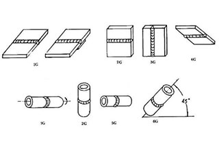
Various manual TIG welding currents for different joints:
| Plate thickness (mm) | Joint form | Welding current (A) | ||
| Flat welding | Vertical welding | Overhead welding | ||
| 1.5 | Docking | 800-100 | 70-90 | 70-90 |
| Lapping | 100-120 | 80-100 | 80-100 | |
| Corner joint | 80-100 | 70-90 | 70-90 | |
| 2.5 | Docking | 100-120 | 90-110 | 90-110 |
| Lapping | 110-130 | 100-120 | 100-120 | |
| Corner joint | 100-120 | 90-110 | 90-110 | |
| 3.2 | Docking | 120-140 | 110-130 | 105-125 |
| Lapping | 130-150 | 120-140 | 120-140 | |
| Corner joint | 120-140 | 110-130 | 115-135 | |
Note: When the plate thickness is less than millimeters, millimeters, and millimeters, the welding current can be taken from the lower limit values listed in this table.
③ Arc Voltage
Arc voltage is the main parameter that determines the width of the weld. In TIG welding, a lower arc voltage is usually used to obtain good protection for the weld pool. The commonly used range of arc voltage is 10-20V.
④ Tungsten Electrode Diameter and End Shape
The choice of tungsten electrode diameter depends on the type of welding power source to be used, as well as the polarity and current magnitude.
At the same time, the sharpness of the tungsten electrode end also has a certain impact on the weld depth, width, and stability. The recommended parameters in the table below are available for selection.
Allowable welding current range for various tungsten electrode diameters:
| Tungsten electrode diameter (mm) | Direct current (A) | AC power (A) | ||||
| Direct connection | Reverse connection | |||||
| Pure tungsten | Thorium tungsten cerium tungsten | Pure tungsten | Thorium tungsten cerium tungsten | Pure tungsten | Thorium tungsten cerium tungsten | |
| 1.6 | 40-130 | 60-150 | 10-20 | 10-20 | 45-90 | 60-120 |
| 2.0 | 75-180 | 100-200 | 15-25 | 15-25 | 65-125 | 85-160 |
| 2.5 | 130-230 | 170-250 | 17-30 | 17-30 | 80-140 | 120-210 |
Before using the tungsten electrode, it is necessary to ensure that its surface is free of burrs and other metal or non-metallic inclusions, and there are no scars, cracks, or other impurities.
Otherwise, arcing may occur in the welding torch clamp and contaminate the weld pool.
The length of the tungsten electrode extension is usually selected 1-2 times the diameter of the tungsten electrode.
Tungsten electrode tip shape and current range:
| Tungsten electrode diameter (mm) | Tip diameter (mm) | Tip angle (°) | DC direct connection | |
| Constant DC (A) | Pulse current (A) | |||
| 12 | 2-15 | 2-25 | ||
| 20 | 5-30 | 5-60 | ||
| 25 | 8-50 | 8-100 | ||
| 30 | 10-70 | 10-140 | ||
| 35 | 12-90 | 12-180 | ||
| 45 | 15-150 | 15-250 | ||
⑤ Welding Speed
The welding speed of TIG welding depends on the thickness of the workpiece and the welding current. Due to the lower current that the tungsten electrode can withstand, the welding speed is usually below 20m/h (controlled within 15-18m/h).
⑥ Gas Flow Rate and Nozzle Diameter
The nozzle diameter depends on the thickness of the workpiece and the joint form, and the gas flow rate needs to be increased correspondingly as the nozzle diameter increases.
When the aperture of the nozzle is 8-12 millimeters, the flow rate of the shielding gas is 5-15 L/min; when the nozzle increases to 14-22 millimeters, the gas flow rate is 10-20 L/min. The gas flow rate is also related to the welding environment.
In the case of strong air flow, the gas flow rate should be increased.
Experienced welders can judge the effect of argon protection by observing the color of the surface of the weld metal during the process.
If the protection effect is not ideal, the argon flow rate should be carefully adjusted, the nozzle diameter should be increased, the area should be increased, and if necessary, the backside argon protection should be increased.
| Material Science | Plate thickness (mm) | Welding position | Welding current (A) | Welding speed (M/MIN) | Tungsten electrode diameter (MM) | Filler wire diameter (MM) | Argon flow rate (L/MIN) | Nozzle diameter (MM) |
| Aluminum alloy | 1.2 | Horizontal and vertical | 65-80 50-70 | 5-8 | ||||
| 2 | Horizontal and horizontal tilting | 110-140 90-120 | 5-85-10 | |||||
| 3 | Horizontal and horizontal tilting | 150-180 130-160 | 7-11 | |||||
| 4 | Horizontal and vertical | 200-230 180-210 | ||||||
| stainless steel | 1 | Flat standing | 50-80 50-80 | |||||
| Flat standing | 80-120 80-120 | |||||||
| Flat standing | 105-150 | |||||||
| Flat standing | 150-200 |
Tungsten inert gas welding process defects.
| Defect | Production reasons | Preventive measure |
| Tungsten inclusion | (1) Contact arc ignition (2) Tungsten electrode melting | (1) Use a high-frequency oscillator or high-voltage pulse generator to start the arc (2) reduce the welding current or increase the diameter of the tungsten electrode, tighten the tungsten electrode clamp and reduce the extension length of the tungsten electrode (3) adjust the cracked or torn tungsten electrode |
| Poor gas protection effect | Unnecessary components such as hydrogen, nitrogen, air, and water vapor are mixed in the gas path | (1) Using argon gas with a purity of% (2) having sufficient advance gas supply and delayed gas stop time (3) correctly connecting water pipes and gas pipes, avoiding confusion (4) doing a good job of pre welding cleaning (5) correctly selecting protective gas flow rate, nozzle size, electrode extension length, etc |
| Arc instability | (1) There is oil stains on the welding part. (2) The size of the joint groove is too narrow. (3) The tungsten electrode is contaminated. (4) The diameter of the tungsten electrode is too large. (5) The arc is too long | (1) Do a good job of pre welding cleaning (2) Widen the groove, shorten the arc length (3) Remove the contaminated part (4) Choose appropriate electrode size and chuck (5) Lower the nozzle distance |
| Excessive loss of tungsten electrode | (1) Poor gas protection, tungsten electrode oxidation (2) Reverse polarity connection (3) Clamp overheating (4) Tungsten electrode diameter too small (5) Tungsten electrode oxidation during stopping welding | (1) Clean the nozzle, shorten the nozzle distance, and appropriately increase the large argon flow rate. (2) Change the polarity of the power supply. (3) Polish the electrode clamping end and replace it with a new one. (4) Increase the diameter of the tungsten electrode. (5) Extend the lag gas supply time by no less than 1S/10A |
Note: Except for the unique defects of TIG welding mentioned above, other defects are basically the same as manual arc welding.
Resistance spot welding is a resistance welding method that assembles and overlaps the weldment joint, and presses it between two electrodes to melt the mother metal into a weld by resistance heat.
The spot welding process can be divided into three stages: preloading the weldment between the electrodes, heating the welding area to the required temperature, and cooling the welding area under the pressure of the electrodes.
The quality of spot welded joints mainly depends on the size of the fusion zone (diameter and penetration rate).
At the same time, surface defects such as excessive indentation, surface cracks, and adhesion damage will also reduce the fatigue strength of the joint.
Characteristics of spot welding process: low voltage, high current, high production efficiency, small deformation, limited to overlap, no need to add welding materials such as welding rods, wires, and flux, easy to achieve automation, mainly used for thin plate structures.
Spot welding electrodes consist of four parts: the end, the main body, the tail (taper or pipe thread), and the cooling hole.
There are five common forms of electrodes.

Where 1 represents the end, 2 represents the main body, 3 represents the tail, and 4 represents the cooling water hole.
Standard shapes of spot welding electrodes:
Spot Welding Electrode Material.
| Material name | Alloy composition mass fraction % | performance | Apply | |||
| Tensile strength MPa | Hardness HB | Conductivity IACSx10-2 | Softening temperature ℃ | |||
| Cold hard pure T2 | Impurities< | 250-360 | 75-100 | 98 | 150-250 | Spot welding of rust resistant aluminum 5A02, 2A21 (LF2, LF21) |
| Cadmium green steel Qcd | Cd, the rest are Cu | 400 | 100-120 | 80-88 | 250-300 | Hardened aluminum 2A12CZ (LY12CZ) after spot welding and quenching |
| Engraved bronze | The rest are Cu | 480-500 | 110-135 | 65-75 | 510 | Spot welding of low-carbon steel Q235, 08, 10, 20 |
| Chromium cobalt steel HD1 | Cr, the rest are Cu | 170-190 | 75 | ≥600 | Steel and stainless steel | |
Basic Electrode Dimensions.
| Diameter D of the electrode body (mm) | Electrode end diameter d (mm) | Tail pipe thread G (in) | ||
| 5-10 | 20-75 | 100 | ||
| Diameter D of electrode body (mm) | Determine based on spot welding process parameters | 1/2“1” | ||
| 12-16 | 20-35 | 35-50 | ||
Pre-weld surface cleaning is crucial for spot welding, which involves removing dirt, oxide film, and other contaminants from the surface of the workpiece.
Mechanical cleaning methods such as sandblasting and polishing are commonly used, which include grinding with a grinding wheel, sanding belt, or wire brush.
Chemical cleaning includes alkali washing to remove oil stains and acid washing to remove rust, followed by passivation (note: chemical cleaning should not be used for parts with enclosed shapes or gaps that are difficult for acid or alkali liquids to flow out).
The main welding parameters for spot welding include electrode pressure, welding time, welding current, switch and size of the electrode working endface.
The spot welding parameters are usually determined based on the material and type of the workpiece, electrode pressure and welding time, and the required fusion diameter welding current.
Spot welding parameters are mainly selected in the following two ways:
(1) Appropriate matching of welding current and welding time. This combination mainly reflects the heating speed of the welding zone. Large current and short time are the hard specifications; conversely, small current and appropriately extended welding time are the soft specifications.
(2) Appropriate matching of welding current and electrode pressure. This combination is based on the principle of no splashing during the welding process.
| Plate thickness (mm) | Electrode end diameter (mm) | Electrode diameter (mm) | Minimum point distance (mm) | Minimum overlap (mm) | Electrode pressure (KN) | Welding time (weeks) | Welding current (A) | Nugget diameter (m) |
| 0.4 | 3.2 | 12 | 8 | 10 | 1.15 | 4 | 5.2 | 4.0 |
| 0.5 | 4.8 | 12 | 9 | 11 | 1.35 | 5 | 6.0 | 4.3 |
| 0.6 | 4.8 | 12 | 10 | 11 | 1.50 | 6 | 6.6 | 4.7 |
| 0.8 | 4.8 | 12 | 12 | 11 | 1.90 | 7 | 7.8 | 5.3 |
| 1.0 | 6.4 | 13 | 18 | 12 | 2.25 | 8 | 8.8 | 5.8 |
| 1.2 | 6.4 | 13 | 20 | 14 | 2.70 | 10 | 9.8 | 6.2 |
| 1.6 | 6.4 | 13 | 27 | 16 | 3.60 | 13 | 11.5 | 6.9 |
| 1.8 | 8.0 | 16 | 31 | 17 | 4.10 | 15 | 12.5 | 7.4 |
| 2.0 | 8.0 | 16 | 35 | 18 | 4.70 | 17 | 13.3 | 7.9 |
| 2.3 | 8.0 | 16 | 40 | 20 | 5.80 | 20 | 15.0 | 8.6 |
| 3.2 | 9.6 | 16 | 40 | 22 | 8.20 | 27 | 17.4 | 10.3 |
Note: This form is for 60Hz AC power frequency. When using 50/60Hz AC power, the frequency should be multiplied by 5/6 (see welding time table).
The plate thickness should be based on the thinnest plate thickness in the overlapping parts.
| Defect | Cause of occurrence | Preventive methods | |
| Nugget size defect | Lack of penetration or small nugget size | Welding current is too low, power on time is too short, and electrode pressure is too high | Adjusting welding parameters |
| Excessive electrode contact area | Trimming electrodes | ||
| Poor surface cleaning | Clean the surface | ||
| Excessive penetration rate | Excessive welding current, prolonged power on time, insufficient electrode pressure | Adjusting welding parameters | |
| Poor electrode cooling conditions | Strengthen cooling and replace with electrode materials with good thermal conductivity | ||
| External defects | Excessive indentation of solder joints and surface overheating | The electrode contact surface is too small | Trimming electrodes |
| Excessive welding current, prolonged power on time, insufficient electrode pressure | Adjusting welding parameters | ||
| Poor electrode cooling conditions | Strengthen cooling and replace with electrode materials with good thermal conductivity | ||
| Local burn through and overflow on the surface, surface splashing | The electrode is too sharp | Repair welding parameters | |
| Foreign objects on the surface of electrodes or welding components | Enhanced cooling | ||
| Insufficient electrode pressure or virtual contact between electrode and weldment | Trimming electrodes | ||
| Radial cracks on the surface of solder joints | Insufficient electrode pressure, insufficient forging force or untimely addition | Clean the surface of electrodes and welding parts | |
| Poor electrode cooling effect | Increase electrode pressure and adjust stroke | ||
| Circular cracks on the surface of solder joints | Welding time too long | Adjusting welding parameters | |
| Surface adhesion and damage of solder joints | Improper selection of electrode materials | Exchange suitable board materials | |
| Tilt of electrode end face | Trimming electrodes | ||
| The surface of the solder joint turns black and the coating layer is damaged | Poor surface cleaning of electrodes and welding parts | Clean the surface | |
| Excessive welding current, long welding time, insufficient electrode pressure | Adjusting welding parameters | ||
The parameters of gas welding and welding code include the selection of flame energy efficiency, the selection of wire diameter, the selection of oxygen pressure according to the welding distance model, the selection of the inclination angle of the welding nozzle, and the selection of the welding speed.
The gas welding flame energy efficiency is expressed in terms of the hourly consumption of acetylene gas (L/H). It is selected based on the thickness of the welded parts, the material properties, and the spatial position of the welded parts.
When welding low carbon steel and alloy steel, the consumption of acetylene can be calculated using the following empirical formula:
In formula,
δ represents the thickness of the steel plate in millimeters, and V represents the flame energy efficiency (acetylene consumption) in liters per hour.
When welding copper with gas, the acetylene consumption can be calculated by the following empirical formula:
V=(150-200)δ.
Choose the welding torch model and nozzle number based on the calculated acetylene consumption, or directly choose them based on the welding plate thickness.
Please refer to the table for the injection and suction type welding torch models and their main parameters.
| Welding torch model | H01-2 | H01-6 | ||||||||
| Welding nozzle number | 1 | 2 | 3 | 4 | 5 | 1 | 2 | 3 | 4 | 5 |
| Welding nozzle aperture (mm) | ||||||||||
| Welding thickness (mm) | ||||||||||
| Oxygen pressure (MPe) | ||||||||||
| Acetylene pressure (MP) | ||||||||||
| Oxygen consumption (m/h) | ||||||||||
| Acetylene consumption (L/h) | 40 | 55 | 80 | 120 | 170 | 170 | 240 | 280 | 330 | 430 |
| Welded metal material | The type of flame to be used | Welded metal material | The type of flame to be used |
| Low and medium carbon steel | Neutral flame | Aluminum and aluminum alloys | Neutral flame or slightly carbonized flame |
| low alloy steel | Neutral flame | Chromium nickel stainless steel | Neutral flame |
| High carbon steel | Mild carbonization flame | Ming stainless steel | Neutral flame or slightly carbonized flame |
| Cast iron | Neutral flame or slightly carbonized flame | Nickel | Mild carbonization flame |
| Purple copper | Neutral flame | Menggang | Mild carbonization flame |
| brass | Mild oxidation flame | Galvanized iron sheet | Mild carbonization flame |
| Tin bronze | Neutral flame | Hard alloy | Mild carbonization flame |
| Monel alloy | Mild oxidation flame | High speed steel | Mild carbonization flame |
| Aluminum, tin | Neutral flame | Tungsten carbide | Mild carbonization flame |
6.3.1 The material of welding wire should be similar to the alloy composition of the workpiece.
The following table of welding wires can be used for gas welding of steel, aluminum and aluminum alloys, as well as copper and copper alloys:
A) Welding wires for various types of steel used in gas welding
| Welding wire name | Welding wire grade | Applicable steel grade |
| Low carbon steel, low alloy structural steel, medium carbon steel welding wire | H08 | Q235 |
| H08A | Q235、20、15g、20g | |
| H08Mn | Medium carbon steel | |
| H08MnA | Q235, 20, 15g, 20g16Mn, 16MnV, medium carbon steel | |
| H12CrMo | 20Medium carbon steel | |
| Austenitic stainless steel welding wire | HoCrl18Ni9 | 0Cr18Ni9 0Cr18Ni9Ti 1Cr18Ni9Ti |
| H1Cr18Ni10Nb | Cr18Ni11Nb | |
| HCr18Ni11Mo3 | Cr18Ni12MoTi Cr18Ni12Mo3Ti |
B) Welding wires for aluminum and aluminum alloys used in gas welding.
| Welding material | Welding wire | Cutting or wire of base material |
| L1 | S (wire) AL-2 | L1 |
| L2 | L1 L2 | |
| L3 | L2 L3 | |
| L4 | L3 L4 | |
| L5 | L4 L5 | |
| L6 | L5 L6 | |
| LF2 | SA1Mg-2 SA1Mg-3 | LF2 LF3 |
| LF3 | SA1Mg-3 SA1Mg-5 | LF3 LF5 |
| LF5 | SA1Mg-3 | LF5 LF6 |
| LF6 | SA1Mg-3 | LF6 |
| LF11 | 8A1Mg-5 | LF11 |
| LF21 | SA1Mn SA1Si-2 | LF12 |
C) Welding wires for copper and copper alloys used in gas welding.
| Welding material | Welding wire name | Welding wire grade |
| Pure copper | Copper wire | HsCu |
| Brass | 1-4 # brass wire | HsCuZn-1~4 |
| White copper | Zinc white copper wire | HsCuZnNi |
| Copper wire | HsCuNi | |
| Bronze | Silicon blue copper wire | HsCuSi |
| Tin blue copper wire | HsCuSn | |
| Aluminum bronze wire | HsCuAl | |
| Nickel aluminum bronze wire | HsCuAlNi |
6.3.2 Selection of Welding Wire Diameter
The selection of welding wire diameter is mainly based on the thickness of the workpiece material.
If the welding wire is too thin, it will melt too quickly and the melting point will fall on the weld seam, which can easily cause poor fusion and uneven weld seams.
If the welding wire is too thick, the melting time of the welding wire will be prolonged, the heat-affected zone will be enlarged, and overheating tissue may occur, which will reduce the welding quality of the joint.
Relationship between workpiece thickness and welding wire diameter:
| Workpiece thickness (mm) | 1-2 | 2-3 | 3-5 | 5-10 | 10-15 |
| Welding wire diameter (mm) | 1-2 | 2-3 | 3-4 | 3-5 | 4-6 |
The tilt angle of the welding nozzle is usually determined based on the thickness of the workpiece, the size of the welding nozzle, and the welding position. A large tilt angle of the welding nozzle results in a concentrated flame, minimal heat loss, high heat input, and rapid heating of the workpiece.
Conversely, a small tilt angle of the welding nozzle results in a dispersed flame, significant heat loss, low heat input, and slow heating of the workpiece. The tilt angle of the welding nozzle is generally within the range of 20°-50°.
Selection of tilt angle for gas welding nozzle:
| Weldment thickness (mm) | ≤1 | 1-3 | 3-5 | 5-7 | 7-10 | 10-15 |
| Welding nozzle inclination angle | 20° | 30° | 40° | 50° | 60° | 70° |
| Parameter | Selection principles |
| Flame type | Types of oxygen acetylene flames, selected according to the table |
| Acetylene consumption and oxygen working pressure | Based on factors such as the melting point of metals and alloys, the thickness and small size of welding parts, thermal conductivity, and joint form, select welding torque and nozzle with appropriate flame energy rate (acetylene consumption), and adjust the oxygen working pressure appropriately according to acetylene consumption. |
| Welding wire diameter | Table selection based on the relationship between workpiece thickness and welding wire diameter |
| Welding nozzle number | Determine based on the thickness, material, and joint form of the weldment |
| Welding nozzle inclination angle | Determine according to the thickness of the welding piece (see the selection of welding nozzle inclination angle) |
| Welding speed | Based on operational skills and the strength of the flame used, try to increase the welding speed as much as possible while ensuring penetration |
| Defect | Cause of occurrence | Preventive measure |
| Crackle | The sulfur content in the weld metal is too high, the welding stress is too high, the flame energy rate is low, and the weld fusion is poor | Control the sulfur content of weld metal, improve flame energy efficiency, and reduce welding stress |
| Stoma | Poor cleaning of welding wires and parts, high sulfur content, incorrect flame composition, and fast welding speed | Strictly clean the surface of the workpiece and control the metal composition of the welding wire; Reasonable selection of flame and welding speed |
| The weld size and welding switch do not meet the requirements | Improper angle of welding groove, uneven assembly gap, improper selection of welding parameters, etc | Reasonable processing of groove angle, strict control of assembly clearance, and correct selection of welding parameters |
| Undercut | Excessive adjustment of flame energy rate, incorrect inclination angle of welding nozzle, improper movement method of welding nozzle and welding wire | Correctly select welding parameters and correct operation methods |
| Burn through | Excessive heating of welding parts, improper operation process, slow welding speed, and prolonged stay at a certain location | Reasonable heating work, adjusting welding speed, and improving operational skills |
| Pit | Excessive flame energy rate, incomplete filling of the melt pool at the end | Pay attention to the welding essentials at the end and choose a reasonable flame energy rate |
| Slag inclusion | Welding edges and layers are not cleaned thoroughly, welding speed is too fast, weld shape coefficient is too small, and welding nozzle inclination angle is not appropriate | Strictly clean the edges and welding layers of the welded parts, control the welding speed, and appropriately increase the shape coefficient of the weld seam |
| Lack of penetration | There are oxides on the surface of the weldment, the groove angle is too small, the flame energy rate is insufficient, and the welding speed is too fast | Strictly clean the surface of the weldment, select appropriate groove angles and gaps, control welding speed and flame energy rate |
| Unfused | The flame energy rate is too low or leans towards the groove side | Choose the appropriate flame energy rate to ensure that the flame is not biased |
| Weld beading | Excessive flame energy rate, slow welding speed, large assembly gap of welding parts, incorrect welding gun movement method, etc | Select appropriate welding speed and flame energy rate; Adjust the assembly gap of the welding parts and use the welding gun correctly |

As the founder of MachineMFG, I have dedicated over a decade of my career to the metalworking industry. My extensive experience has allowed me to become an expert in the fields of sheet metal fabrication, machining, mechanical engineering, and machine tools for metals. I am constantly thinking, reading, and writing about these subjects, constantly striving to stay at the forefront of my field. Let my knowledge and expertise be an asset to your business.