Five-axis CNC Machine: The Basic Guide
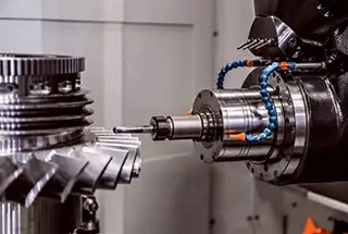
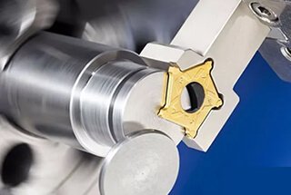
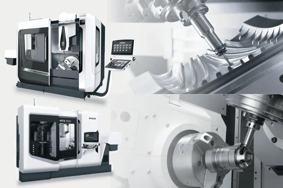
Imagine a machine so precise it can carve out the most intricate details on a jet engine part. This is the power of the five-axis CNC machine. Unlike traditional three-axis…
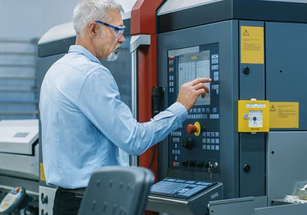
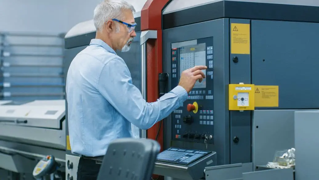
Imagine a machine that can precisely shape metal with minimal human intervention, tirelessly producing complex parts for industries like aerospace and automotive. This is the essence of CNC (Computer Numerical Control) machines. In this blog, we delve into the key components and functions of CNC machines, exploring how they revolutionize modern manufacturing. By understanding these advanced tools, you’ll gain insight into their pivotal role in enhancing production efficiency and product quality in today’s competitive market.
With the continuous advancement of social production and technology, new industrial products emerge without end.
The machinery manufacturing industry, as the backbone of the national industry, has seen increasingly sophisticated products, particularly the mechanical components required in fields such as aerospace, navigation, and military, which demand higher precision, more complex shapes, and often smaller batch sizes.
The processing of these products requires frequent modifications or adjustments to the equipment.
Ordinary machine tools or highly specialized automatic machine tools are not capable of meeting these requirements.
At the same time, production enterprises are facing increased market competition and are in urgent need of improving production efficiency, product quality, and reducing production costs.
In this scenario, a new type of production equipment, the numerical control machine tool, emerged.
It integrates the technical advancements of electronic computers, automatic control, servo drives, precision measurement, and new mechanical structures, forming the foundation of the future mechanical industry and pointing towards the development direction of mechanical manufacturing equipment.
The development of CNC machine tools started in the United States. In 1948, Parsons Co. had a preliminary idea to develop a CNC machine tool while working on a project to create a machine tool for processing the inspection template for helicopter blade profiles. The following year, with support from the United States Air Force Logistics Department, Parsons officially partnered with the Servo Mechanism Laboratory of the Massachusetts Institute of Technology to begin the development of CNC machine tools.
After three years of research, the world’s first test prototype of a CNC machine tool was successfully produced in 1952. The machine was a linear interpolation three-coordinate continuous control system milling machine, based on the principle of pulse multiplier. Its numerical control system used all electronic tube components, and its numerical control device was larger than the machine itself.
After three more years of improvement and research into automatic programming, the machine tool was ready for trials in 1955. Other countries, including Germany, Britain, Japan, the former Soviet Union, and Sweden, soon followed suit and started researching, developing, and producing CNC machine tools.
In 1959, Keaney & Trecker of the United States successfully developed the first Machining Center, a CNC machine tool with an automatic tool change device and rotary table that could process multiple planes of a workpiece in one clamping process.
Until the end of the 1950s, CNC machine tools were limited to aviation and military industrial applications, mainly due to cost and other factors. The majority of the available machines were continuous control systems. By the 1960s, the application of transistors improved the reliability of CNC systems and reduced their cost, making it possible for some civil industries to start developing CNC machine tools, mostly point positioning control machines such as drilling machines and punch machines.
Numerical control technology has since been applied not only to machine tools, but also to welding machines, flame cutting machines, and more, continuously expanding its range of applications.
The development of CNC machine tools has undergone five stages since its successful creation in the United States in 1952. With advancements in electronic, computer, automatic control, and precision measurement technologies, CNC machine tools have continuously evolved and improved.
The first generation of CNC machine tools (1952-1959) utilized a special numerical control device (Numerical Control, NC).
The second generation (1959-1965) saw the adoption of NC systems with transistor circuits.
In the third generation (1965-1970), NC systems with small and medium-sized integrated circuits were utilized.
The fourth generation (1970-1974) saw the implementation of computer numerical control (CNC) systems with large-scale integrated circuits.
The fifth generation (1974-present) utilizes microcomputer-controlled (MNC) systems.
Recently, the maturity of microelectronics and computer technology has led to the creation of computer-direct numerical control (DNC) systems, flexible manufacturing systems (FMS), and computer-integrated manufacturing systems (CIMS). These advanced automatic production systems are based on CNC machine tools and represent the future direction of their development.
(1) Computer direct numerical control system
The Direct Numerical Control (DNC) system utilizes a computer to program multiple CNC machine tools automatically. The programming results are then directly transmitted to the control box of each machine tool via a data line.
The central computer boasts ample memory capacity, enabling it to efficiently store, manage, and control numerous part programs.
Thanks to its time-sharing operating system, the central computer can manage and control a group of CNC machine tools simultaneously, earning it the moniker “computer group control system.”
Currently, each CNC machine tool in the DNC system has its independent CNC system and is connected to the central computer to achieve hierarchical control, as opposed to allowing the computer to control all CNC devices at once.
With the advancement of DNC technology, the central computer is now used not only to program parts and control the processing of CNC machine tools, but also to further control the transmission of workpieces and tools, resulting in a computer-controlled automatic production line of CNC machine tools. This provides favorable conditions for the growth of flexible manufacturing systems.
(2) Flexible manufacturing system
The Flexible Manufacturing System (FMS) is also referred to as the “computer group control automatic line.” It connects a group of CNC machine tools with an automatic transmission system and is placed under the control of a single computer, forming a complete manufacturing system.
The FMS is characterized by a master computer that manages the hardware and software of the entire system. It uses the DNC mode to control two or more CNC machining center machines and schedules and automatically transfers workpieces between the machines.
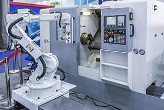
Automatic loading and unloading of parts can be achieved through the use of devices such as exchange worktables or industrial robots, allowing for 24-hour production with minimal supervision.
For instance, a FMS from FANUC in Japan includes 60 CNC machine tools, 52 industrial robots, two unmanned automatic carriers, and an automatic warehouse. This system has the capability to process 10,000 servo motors per month.
(3) Computer Integrated Manufacturing System
The Computer Integrated Manufacturing System (CIMS) is a flexible and integrated manufacturing system that employs the most advanced computer technology to control the entire process, from ordering to design, process, manufacturing, and sales. This is done with the goal of achieving high efficiency through the integration of information systems.
CIMS has been gradually improved based on the automation of production processes, such as computer-aided design, computer-aided process planning, computer-aided manufacturing, and flexible manufacturing systems, in conjunction with the development of other management information systems.
It boasts the analysis and control capabilities of various computer and software systems, allowing it to link the production activities of the entire plant and eventually achieve comprehensive automation throughout the entire facility.
Since 1958, the Beijing Machine Tool Research Institute and Tsinghua University first developed CNC machine tools and successfully trial-produced the first electronic tube CNC machine tool.
From 1965 to the early 1970s, the development of the transistor numerical control system was initiated, and successful developments of the split taper numerical control milling machine and non-circular gear shaper were achieved. Research on automatic programming for NC milling machine machining of plane parts was also carried out.
From 1972 to 1979, CNC machine tools entered the production and usage stage. Tsinghua University successfully developed the integrated circuit CNC system, and research and application of numerical control technology in various fields such as turning, milling, boring, grinding, gear processing, and electrical machining were conducted. The CNC machining center machine tool was also developed, and small batches of CNC lifting table milling machines and CNC gear processing machines were produced and supplied to the market.
Starting in the 1980s, with the implementation of the reform and opening-up policy, China introduced advanced CNC technology from countries such as Japan, the United States, and Germany. The Beijing Machine Tool Research Institute imported the manufacturing technology of FANUC3, FANUC5, FANUC6, and FANUC7 series products from Japan’s FANUC Company, and the Shanghai Machine Tool Research Institute introduced the MTC-1 numerical control system from GE.
Based on the introduction, digestion, and absorption of foreign advanced technologies, the Beijing Machine Tool Research Institute developed the BSO3 economical CNC system and the BSO4 full-function CNC system. The 706 Institute of the Ministry of Aeronautics and Astronautics developed the MNC864 CNC system.
By the end of the “Eighth Five-Year Plan,” there were over 200 varieties of CNC machine tools in China with an output of 10,000 sets per year, which was 500 times more than in 1980.
China’s CNC machine tools have made significant advancements in variety, performance, and control level, and the CNC technology has entered a stage of development that builds upon the past and opens up new possibilities for the future.
The important development trends in CNC machine tools are high precision, high speed, high flexibility, multi-functionality, and high automation at the technical level.
For a single machine, it is crucial to not only enhance its flexibility and automation but also improve its adaptability to flexible manufacturing systems and computer integrated systems.
Domestic CNC equipment has seen advancements in its spindle speed, which now reaches 10,000 to 40,000 revolutions per minute (r/min), and feed speed, which can now reach 30 to 60 meters per minute (m/min). Additionally, the tool change time is less than 2 seconds, and the surface roughness is less than 0.008 micrometers (μm).
In terms of numerical control systems, leading manufacturers such as FANUC in Japan, SIEMENS in Germany, and A-B in the United States are developing their products with a focus on serialization, modularization, high performance, and completeness.
These CNC systems all use 16-bit and 32-bit microprocessors, a standard bus, software and hardware module structures, with expanded memory capacities of over 1 megabyte (MB) and machine tool resolutions of up to 0.1 μm.
The high-speed feed rate can now reach 100 m/min, the number of control axes has increased to 16, and advanced electrical assembly technology has been adopted.
In terms of drive systems, AC drive systems have rapidly advanced. AC drives have evolved from analog to digital and the controllers based on analog devices such as operational amplifiers are being replaced by digital integrated elements based on microprocessors, thereby overcoming the weaknesses of zero drift and temperature drift.
CNC (Computer Numerical Control) technology is a machine tool control system that was developed in the mid-20th century. It allows for the control of the motion of a machine tool and its processing process through the use of digital signals.
A machine tool equipped with a CNC system is known as a NC (Numerical Control) machine tool. This type of machine tool is considered a mechatronic product that integrates advanced technologies such as computer technology, automatic control technology, precision measurement technology, communication technology, and precision mechanical technology.
The International Federation of Information Processing’s (IFIP) Fifth Technical Committee defines CNC machine tools as follows: “CNC machine tools are machine tools that are equipped with a program control system, capable of logically processing programs using specific codes and other symbol coding instructions.”
There are various types of CNC machine tools, but all of them consist of several fundamental components such as the control medium, CNC system, servo system, auxiliary control system, and machine tool body, as depicted in Figure 1-1.
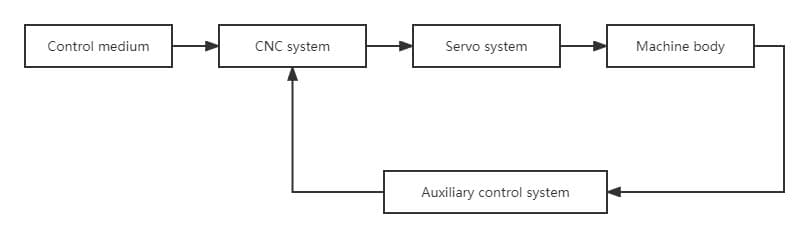
Fig. 1-1 Composition of CNC machine tool
(1) Control medium
When the numerical control system is in operation, the machine tool implements the operator’s intention without the need for direct manual operation. This requires a relationship to be established between the human and the machine tool, which is facilitated by the control medium.
The control medium acts as an intermediary, storing all the necessary information for processing a part, including operation information and tool-to-workpiece displacement information. It serves as the information carrier that transmits the part processing information to the numerical control device.
There are various forms of control media, which vary based on the type of numerical control device used. Common control media include perforated paper tape, perforated cards, magnetic tape, magnetic disks, and USB interface media.
The processing information recorded on the control medium is transmitted to the numerical control device through an input device, such as a photoelectric paper tape input machine, tape recorder, disk drive, or USB interface.
Some CNC machine tools also allow for direct input of programs and data using digital dials, digital pins, or a keyboard. With the advancement of CAD/CAM technology, some numerical control devices can use CAD/CAM software on other computers to program, and then communicate with the numerical control system through a computer network (such as LAN) to directly transmit the program and data to the numerical control device.
(2) CNC system
The CNC device is a control system and the central component of a CNC machine tool. It can automatically read the preset numbers on the input carrier and decode them, allowing the machine tool to perform its functions and process parts.
The NC system typically consists of an input device, controller, arithmetic unit, and output device, as depicted in Figure 1-2.
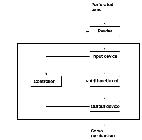
Fig. 1-2 CNC device structure
The input device receives code from the perforated tape reader and decodes it before inputting it into the appropriate register. These instructions and data serve as the source material for control and operation.
The controller receives instructions from the input device and manages the arithmetic unit and input device according to the instructions. This enables various operations of the machine tool, such as controlling the movement of the workbench along a specific coordinate axis, adjusting the speed of the main shaft, and switching the coolant. The controller also manages the machine’s working cycle, including starting or stopping the reading machine, calculating with the arithmetic unit, and controlling output signals.
The arithmetic unit performs operations on the data sent from the input device based on the instructions from the controller. It continuously sends calculation results to the output device for the servo system to carry out the required movements. For complex parts in machining, the arithmetic unit’s key function is to conduct interpolation operations.
Interpolation operations involve inputting coordinate data for a starting and end point on the workpiece contour from each program segment into the arithmetic unit. After the operation, data is encrypted between the starting and end points, and the calculation results are sent to the output device per the controller’s instructions.
The output device sends the calculation results from the arithmetic unit to the servo system as directed by the controller, driving the corresponding coordinate axis through power amplification and allowing the machine tool to complete the motion of the tool relative to the workpiece.
Currently, microcomputers are used as numerical control devices. The central processing unit (CPU) of the microcomputer, also known as the microprocessor, is a large-scale integrated circuit that combines the arithmetic unit and controller into one chip. The input and output circuits use large-scale integrated circuits, known as I/O interfaces.
The microcomputer has a large number of registers and utilizes high-density storage media, such as semiconductor memory and disk memory. Memory can be divided into read-only memory (ROM) and random access memory (RAM). ROM stores the system’s control program, while RAM stores the system’s operating parameters or the user’s processing program.
The working principle of the microcomputer numerical control device is similar to that of the hardware numerical control device, but it uses general hardware and achieves different functions through software changes, making it more flexible and economical.
(3) Servo system
The Servo System is a crucial component of the CNC system, consisting of a servo drive motor and a servo drive device. It is responsible for executing the commands from the CNC system.
The Servo System receives command information from the CNC system and drives the moving parts of the machine tool to move or perform actions according to the requirements of the command information. This results in the processing of the workpiece to meet the desired specifications.
The instruction information is represented by pulse information. The displacement of the machine tool’s moving parts caused by each pulse is known as the pulse equivalent. Common pulse equivalents in machining include 0.01mm/pulse, 0.005mm/pulse, and 0.001mm/pulse. Currently, the pulse equivalent in NC systems is typically 0.001mm/pulse.
The quality of the Servo System directly affects the speed, position, and accuracy of CNC machining, making it a key component of CNC machine tools. The driving device used in the servo mechanism varies depending on the CNC system.
Open-loop systems often use stepping motors and electro-hydraulic pulse motors, while closed-loop systems use wide-speed DC motors and electro-hydraulic servo drives.
(4) Auxiliary control system
The Auxiliary Control System is a powerful current control device that connects the Numerical Control Device to the mechanical and hydraulic components of the machine tool. It receives command signals, such as changes in main motion speed, tool selection and exchange, and actions of auxiliary devices, from the Numerical Control Device. After necessary processing, logic judgment, and power amplification, the system directly drives the corresponding electrical, hydraulic, pneumatic, and mechanical components to complete various specified actions. Moreover, some switch signals are transmitted back to the Numerical Control Device for further processing through the Auxiliary Control System.
(5) Machine body
The Machine Body is the central component of the CNC Machine Tool, comprising of the basic large parts (such as the bed and the base) and various moving parts (such as the workbench, bed saddle, and spindle). It is a mechanical component that performs various cutting operations and is an improvement over conventional machine tools.
The CNC Machine Tool possesses the following features:
The design of CNC machine tools has undergone significant changes, including alterations to its external appearance, overall arrangement, component composition, and operational mechanisms in comparison to traditional manual machine tools.
These modifications aim to accommodate the needs of CNC machine tools and effectively utilize its unique features.
As a result, a novel approach to the design of CNC machine tools must be established.
Currently, there exist various types of CNC machine tools with differing structures and functions. They can be categorized based on the following methods.
CNC machine tools can be classified based on their motion tracks into three categories: point-controlled, straight-line controlled, and contour controlled.
(1) Point control CNC machine tool
Positioning control, also known as Point-to-Point Control, is a technique used to precisely position moving parts from one position to another. The key feature of this type of control is that it focuses solely on the accurate positioning of the moving parts and does not have strict requirements for their trajectory during movement. No processing is performed during the movement and positioning process.
To minimize the movement and positioning time of the moving parts, the tool moves quickly from one point to another, reducing speed as it approaches the target position, ensuring accurate positioning. This process is depicted in Figure 1-3.
Point-to-Point Control is commonly used in machine tools such as CNC coordinate boring machines, CNC drilling machines, CNC spot welding machines, and CNC bending machines. The corresponding numerical control device used for this type of control is known as a Point-to-Point Control Numerical Control Device.
(2) Straight cut control CNC machine tool
Straight Cut Control, also known as Parallel Cut Control, is a technique used in CNC machine tools to ensure that the motion between two points is a straight line and to control the speed of movement. This type of control is necessary when cutting is performed during the movement between two points.
The characteristic of a Straight Cut Control CNC machine tool is that it not only controls the precise position between two related points, but also controls the speed and trajectory of the movement. The trajectory is typically composed of linear segments parallel to each axis.
Compared to Point-to-Point Control CNC machine tools, Straight Cut Control CNC machine tools have the added capability of cutting along a coordinate axis during movement and have more advanced auxiliary functions.
The processing of Straight Cut Control is depicted in Figure 1-4.
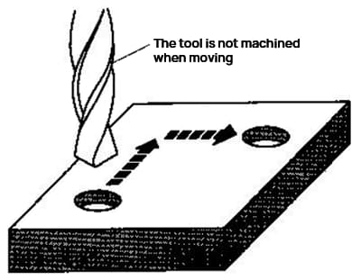
Fig. 1-3 Schematic diagram of point control processing
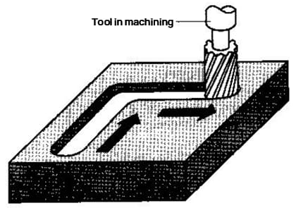
Fig. 1-4 Schematic diagram of linear control processing
This type of machine tool, which utilizes Straight Cut Control, includes CNC coordinate lathes, CNC grinding machines, and CNC boring and milling machines. The corresponding numerical control device used is known as a Straight Cut Control Numerical Control Device.
(3) Contour control CNC machine tool
Contour Control, also known as Continuous Control, is a function commonly found in most CNC machine tools. This type of control is characterized by the ability to control multiple axes simultaneously and the use of interpolation functions.
Contour Control CNC machine tools not only control the position and speed of the tool during machining, but also have the capability to process curves or surfaces of any shape.
The processing of Contour Control is depicted in Figure 1-5.
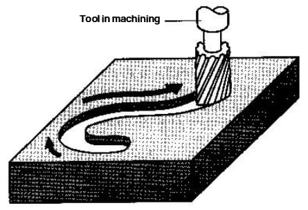
Fig. 1-5 Schematic diagram of contour control processing
CNC coordinate lathes, CNC milling machines, and machining centers are examples of machine tools that utilize Contour Control. The corresponding numerical control device used is known as a Contour Control Device.
Compared to Point-to-Point and Straight Cut Control devices, the Contour Control Device is much more complex and has more advanced functions.
According to the classification of servo systems, CNC machine tools can be divided into three types: open-loop control, closed-loop control, and semi-closed-loop control.
Related reading: Open Loop vs. Closed Loop: The Differences Explained
(1) Open-loop control CNC machine tool
Open-loop control CNC machine tools typically do not have position detection components, and the servo drive components are typically stepper motors. Upon receipt of each feed pulse sent by the numerical control device, the pulse is amplified and drives the stepper motor to rotate by a fixed angle, which then drives the worktable to move through mechanical transmission.
The open-loop servo system is illustrated in Figure 1-6. This system lacks a feedback value from the controlled object, and its accuracy is entirely dependent on the step accuracy of the stepper motor and the accuracy of the mechanical transmission. Despite its simple control circuit, which is easy to adjust, the accuracy of the system is limited, typically up to ±0.02mm. This type of system is commonly used in small or economically priced CNC machine tools.
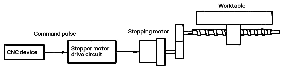
Fig. 1-6 Open-loop servo system
(2) Closed-loop control CNC machine tool
Closed-loop control CNC machine tools typically have position detection elements that can detect the actual position of the worktable at any time and provide this information back to the CNC device. The CNC device then compares the actual position with the set command value, and uses the difference to control the servo motor until the difference is zero.
These types of machine tools are usually driven by DC servo motors or AC servo motors. The position detection elements may include linear gratings, magnetic gratings, and synchronous inductors. The closed-loop servo system is depicted in Figure 1-7.

Fig. 1-7 Closed loop servo system
The working principle of the closed-loop servo system reveals that the system accuracy primarily depends on the accuracy of the position detection device. In theory, the system can completely eliminate the impact of errors in the manufacturing of transmission components on the processing of the workpiece, leading to high processing accuracy.
However, the design and adjustment of the closed-loop servo system are challenging. The linear displacement detection element is relatively expensive and is mainly used in boring and milling machines, ultra-precision lathes, and machining centers that have high accuracy requirements.
(3) Semi-closed loop control CNC machine tool
Semi-closed-loop control CNC machine tools typically have a position detection element installed on the axis of the servo motor or the end of the ball screw. This system does not directly provide feedback on the displacement of the machine tool, but instead detects the rotation angle of the servo system. This information is then fed back to the CNC device for comparison with the command, and the difference is used to control the servo motor. The semi-closed-loop servo system is depicted in Figure 1-8.
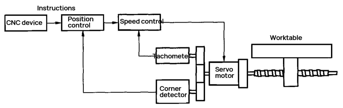
Fig. 1-8 Semi-closed loop servo system
The semi-closed loop servo system has an advantage in debugging because its feedback signal is taken from the motor shaft rotation, meaning that the mechanical transmission device outside the feedback loop and its nonlinear factors such as stiffness and intermittence do not affect the system stability.
However, the positioning accuracy of a machine tool primarily relies on the accuracy of the mechanical transmission device. To address this, modern numerical control devices have functions for compensating for pitch errors and intermittence. This means that it’s not necessary to have very high accuracy for all parts of the transmission device, and the accuracy can be improved to an acceptable level for most users through compensation.
Furthermore, linear displacement detection devices are more expensive than angular displacement detection devices. Hence, except for large machine tools that require high positioning accuracy or long travel and cannot use ball screws, the majority of CNC machine tools utilize semi-closed loop servo systems.
CNC machine tools can be classified into various types based on their intended processing purposes. These include metal cutting CNC machine tools, metal forming CNC machine tools, CNC special machining machines, and others.
(1) CNC machine tools for metal cutting
CNC machine tools for metal cutting include lathes, drilling machines, milling machines, grinding machines, boring machines, and machining centers.
Machine tools for cutting were among the first to be developed.
Today, there are many types of machines available, each with its own distinct set of functions.
Machining centers are equipped with the capability of automatic tool change.
These machine tools feature an island magazine that can hold anywhere from 10 to 100 cutters.
One of their key benefits is the ability to clamp the workpiece in one go, allowing for multiple processes to be completed at once.
To further enhance production efficiency, some machining centers are designed with dual worktables that can be swapped out for processing and loading/unloading simultaneously.
(2) CNC machine tools for metal forming
CNC machine tools for metal forming include bending machines, combined presses, and rotary head presses.
The development of this type of machine tool began later, but it is currently experiencing rapid growth.
(3) CNC special machining machine
CNC special machining machines include wire cutting machines, electric discharge machining machines, flame cutting machines, and laser cutting machines, among others.
(4) Other types of CNC machine tools
Other types of CNC machine tools include Coordinate Measuring Machines (CNC CMMs), among others.
CNC machine tools can be classified into three grades based on the main technical parameters, functional indicators, and functional levels of their key components in the CNC system: low, medium, and high.
In China, CNC machine tools are also classified into full-function, universal, and economical categories.
The criteria for these classifications are relative and have changed over time. They are generally evaluated based on factors such as:
(1) Grade of control system CPU
Low-grade CNC systems typically employ 8-bit CPUs, while medium-grade and high-end systems utilize 16-bit or 64-bit CPUs. Some CNC systems have now adopted the use of 64-bit CPUs.
(2) Resolution and feed rate
The resolution refers to the smallest unit of displacement that can be detected by the displacement detection device. A higher resolution leads to greater detection accuracy, which is determined by the type and manufacturing precision of the detection device.
It is commonly believed that the resolution is 10 μm.
For low-grade CNC machine tools, the feed speed is typically between 8-10 m/min and the resolution is 1 μm. For mid-range CNC machine tools, the feed speed is between 10-20 m/min and the resolution is 0.1 μm. For high-grade CNC machine tools, the feed speed is between 15-20 m/min and the resolution is 0.1 μm.
In general, it is recommended that the resolution be at least one order of magnitude higher than the required machining accuracy of the machine tool.
(3) Servo system type
Typically, low-grade CNC machine tools utilize an open-loop and stepping motor feed system, while medium to high-end CNC machine tools employ either a semi-closed-loop or closed-loop DC servo or AC servo system.
(4) Number of coordinate linkage axes
The number of linked axes is often used as a criterion to classify the grade of CNC machine tools.
Based on the number of axes that are controlled simultaneously, CNC machine tools can be divided into categories such as 2-axis linkage, 3-axis linkage, 2.5-axis linkage (where only 2 axes can be linked at any given time in the 3-axis system, with the remaining axis being controlled either point-wise or linearly), 4-axis linkage, 5-axis linkage, etc.
Low-grade CNC machine tools typically have a maximum of 2 linked axes, while intermediate to high-end CNC machine tools usually have 3 to 5 linked axes.
(5) Communication function
Low-grade CNC systems typically lack communication capabilities. Mid-range CNC systems may have RS-232C or Direct Numerical Control (DNC) interfaces. High-end CNC systems may also have a manufacturing automation protocol (MAP) communication interface and networking functionality.
(6) Display function
Low-grade CNC systems typically have limited display options, such as a simple digital tube display or monochrome CRT character display. Mid-range CNC systems have a more advanced CRT display, which includes character display as well as two-dimensional graphics, human-machine interface, status display, and self-diagnosis functions. High-end CNC systems may also feature 3D graphics display and graphics editing capabilities.
According to the composition of the NC device, it can be classified into two types: the hard-wired CNC system and the soft-wired CNC system.
(1) Hardwire CNC system
The hard-wired numerical control system utilizes a hard-wired numerical control device. The input processing, interpolation operation, and control functions are all achieved through the use of a specialized fixed combination logic circuit. The combination logic circuit for different function machine tools varies. In order to change, increase, or decrease the control and calculation functions, it is necessary to alter the hardware circuit of the numerical control device, resulting in a lack of versatility and flexibility, a lengthy manufacturing cycle, and a high cost. Most CNC machine tools before the early 1970s fall into this category.
(2) Flexible wire CNC system
The Flexible Wire Numerical Control System, also known as the Computer Numerical Control System, utilizes a flexible wire numerical control device. The hardware circuit of this device is composed of a microcomputer and a general or specialized large-scale integrated circuit.
The majority of the functions of the numerical control machine tool are executed through the system software, resulting in varying system software for numerical control machine tools with distinct functions. Modifying, adding, or reducing system functions does not require changes to the hardware circuit, only adjustments to the system software, which enhances the system’s flexibility. The universal nature of the hardware circuit also facilitates mass production, improves quality and reliability, shortens the manufacturing cycle, and reduces costs.
Since the mid-1970s, advancements in microelectronics technology, the advent of microcomputers, and the continual improvement of integrated circuit integration have resulted in the continuous development and improvement of the computer numerical control system. Currently, almost all numerical control machine tools utilize the Flexible Wire Numerical Control System.
Compared to conventional machine tools, CNC machine tools are highly efficient automatic machines that integrate both electromechanical components. They possess the following unique processing characteristics:
(1) Wide adaptability and high flexibility
When the NC machine tool needs to process a different object, it only requires the input of a revised processing program to initiate the processing. In certain instances, even modifying just a portion of the program or using specific instructions can result in successful machining. For example, parts with identical shapes but different dimensions can be processed using the “zoom function” instructions.
This offers significant convenience for single-piece, small-batch, and multi-variety production, product modification, and trial production of new products. It also significantly reduces the production preparation and trial production cycle.
(2) High machining accuracy and stable quality
The numerical control machine tool utilizes a digital servo system, causing the numerical control device to output a pulse, resulting in a corresponding displacement (known as pulse equivalent) produced by the servo actuator, with a precision of 0.1 to 1 μm.
The machine tool’s transmission lead screw features intermittent compensation, allowing for the control of pitch and transmission errors through its closed-loop system, resulting in high processing accuracy.
For instance, precision machining centers typically exhibit a positioning accuracy of (0.005 to 0.008) mm per 300mm length and a repetition accuracy of 0.001 mm.
Furthermore, CNC machine tools boast good structural rigidity and thermal stability, ensuring high manufacturing accuracy.
Their automatic processing mode eliminates the potential for operator error, resulting in stable processing quality and a high rate of qualification. Parts processed in the same batch are also guaranteed to have consistent geometric dimensions.
CNC machine tools are capable of multi-axis linkage and can process complex surfaces that would be difficult or even impossible with traditional machine tools.
(3) High processing productivity
The CNC machine tool allows for the selection of the most favorable processing parameters, enabling the continuous processing of multiple processes.
It also allows for multi-machine supervision.
By implementing acceleration and deceleration measures, the moving parts of the machine tool can move and locate quickly, significantly reducing idle time during the processing process.
(4) Good economic efficiency can be obtained
Despite the high equipment costs, including depreciation, maintenance, and power consumption, associated with each part of the CNC machine tool, it offers high production efficiency and saves time on auxiliary tasks such as line drawing, machine tool adjustment, and processing inspection during single or small batch production, ultimately reducing direct production costs.
The stable machining accuracy of CNC machine tools results in a reduced scrap rate, further reducing production costs.
The performance characteristics of CNC machine tools dictate its range of applications.
For NC machining, the objects being machined can be broadly categorized into three groups based on their suitability.
(1) Most suitable class
Parts requiring high machining accuracy and complex shapes and structures, particularly those with intricate curves and surface profiles or unobstructed inner cavities, are challenging to process, test, and guarantee quality with traditional machine tools.
These parts, which require multiple processes such as milling, drilling, reaming, spot facing, or tapping to be completed in a single clamping, are particularly well-suited for CNC machine tools.
(2) More adaptable
Expensive parts that are difficult to obtain as blanks and cannot be scrapped present challenges when processed on traditional machine tools. Factors such as machine tool adjustment, operator skill, working conditions, and others can easily result in defective or scrap products.
For reliable results, it is recommended to process these parts on a CNC machine tool.
Parts with low production efficiency, high labor intensity, and difficulty in maintaining consistent quality are typically processed on traditional machine tools.
This includes parts used for modification comparison and performance testing, as dimensional consistency is crucial, as well as parts for multi-variety, multi-specification, single-piece, and small-batch production.
(3) Inadaptable
Parts that require manual alignment are processed or positioned using a rough datum as a reference.
CNC machine tools without an online detection system can automatically detect and adjust the position coordinates of parts, ensuring a consistent machining allowance.
Parts or processing requirements that must be performed with specific equipment or according to a template or sample are also suited for CNC machine tools.
As the performance of CNC machine tools improves, the cost decreases, and the functions are enhanced, along with the continuous improvement of tools and auxiliary tools used in CNC processing and the advancement of CNC processing technology, CNC machine tools are increasingly used for mass production due to their high automation, precision, and centralized technology.
Adaptability is relative and subject to change with the development of science and technology.
The 21st century has seen the onset of a rapid development of the knowledge economy. Traditional manufacturing technology and methods are undergoing a significant transformation, with advanced manufacturing technologies being increasingly adopted to drive growth in the manufacturing industry.
These advanced manufacturing technologies include rapid prototyping, virtual manufacturing technology, flexible manufacturing cells, and flexible manufacturing systems, which have been gradually implemented in recent years.
Due to the diversification of demand and the shorter product life cycle, there has been a decrease in the batch size of parts and products and a reduction in delivery time.
To accommodate these changes in the market, advanced part prototype manufacturing technology, known as rapid prototype manufacturing or “laminated manufacturing” technology, was developed in the late 1980s, building on the full development of CAD/CAM, data processing, CNC, and laser sensing technology.
Rapid prototyping, along with virtual manufacturing technology, is considered one of the two pillars of the future manufacturing industry.
(1) Basic principles of rapid prototyping
Rapid prototyping is a system technology that combines CAD technology, numerical control technology, laser processing technology, and material technology to achieve integration from part design to 3D solid prototype manufacturing.
It uses the principle of software discretization and material accumulation to form parts.
The principle of rapid prototype manufacturing is depicted in Figure 1-9.
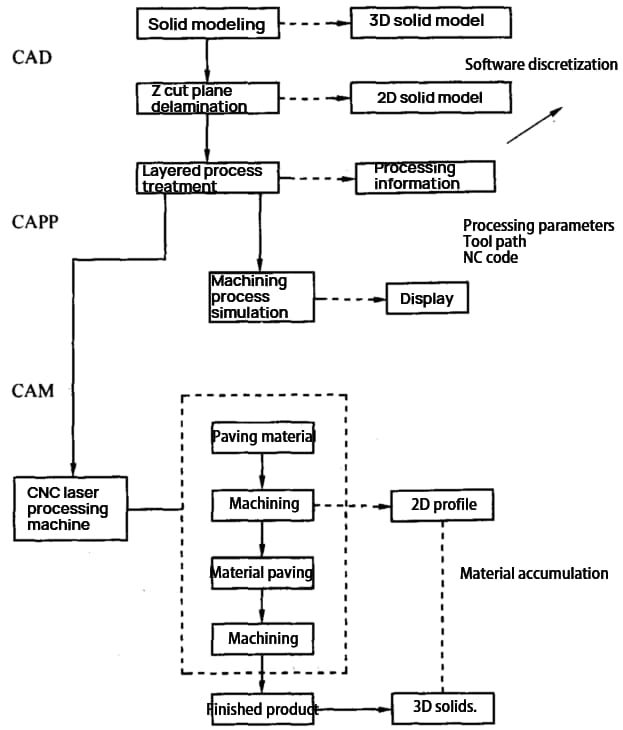
Fig. 1-9 Rapid Prototype Manufacturing Principle
The specific process is as follows:
① Utilize CAD software to design the 3D surface or solid model of the part, or obtain 3D contour data from part sample scanning if a pre-existing part is available.
② Based on the process requirements, the CAD model is sectioned in a designated coordinate direction, such as the Z direction, with a specific thickness, generating two-dimensional plane information for each section.
Each layer is typically 0.05 to 0.5mm thick, with 0.1mm being a commonly used value to ensure a smooth and efficient prototype.
③ Process the layer information, choose the processing parameters, and the system will automatically generate the tool movement path and NC machining code.
④ Confirm the correctness of the NC code through a simulation of the machining process.
⑤ The numerical control device precisely controls the movement of the laser beam or other tools and processes the appropriate section shape through contour scanning on the current working layer (two-dimensional).
⑥ A new layer of forming material is added and the next processing step is carried out until the entire part is processed.
The rapid prototyping process can be seen as a progression from 3D to 2D (software discretization) and then from 2D to 3D (material accumulation).
In addition to quickly generating the original design as a real part, rapid prototyping can also quickly replicate a real part (including zooming in, zooming out, and modifications).
(2) Main process methods of rapid prototyping technology
① Light Curing Solid Forming Manufacturing Method (LSL Method)
The LSL method is a rapid prototyping method that utilizes various resins as the forming material and a He-Cd laser as the energy source, with resin curing being its main characteristic.
② Laminated Object Manufacturing (LOM)
The LOM method uses sheet materials such as film, plastic film, or composite materials as its material, a CO2 laser as its energy source, and laser beam cutting to form the contour of a layer. The layers are bonded through heating and pressure to create the final shape of the part.
This method has a wide range of materials and is cost-effective.
③ Selective Laser Sintering Manufacturing Method (SLS Method)
The SLS method uses a variety of powders, such as metal, ceramic, wax powder, plastic, etc., and a CO2 high-power laser to heat the powder until it is sintered into a block. The powder is paved using rollers.
This method can be used to process metal parts that can be used directly.
④ Fused Deposition Modeling (FDM) Method
The FDM method uses a wax wire as its raw material and electric heating to melt the wax wire into a liquid form. The wax liquid is then deposited at designated positions and fixed, with the parts being processed layer by layer.
This method has low pollution and can be recycled.
(3) Characteristics of rapid prototyping
The following are the characteristics of rapid prototyping methods:
As a result, rapid prototyping methods are mainly used for new product development, rapid single and small batch parts manufacturing, complex part manufacturing, mold design and manufacturing, and the processing and manufacturing of difficult-to-process material parts.
Virtual Manufacturing Technology is a computer-supported technology that models all production and operation activities of an enterprise through simulation technology and virtual reality technology. It allows for virtual product design on a computer.
This technology can encompass all enterprise functions, including processing and manufacturing, planning, generation and scheduling, operation management, cost and financial management, quality management, and marketing.
Once the best operation parameters are obtained from the system, the physical operations of the enterprise can be carried out accordingly. Virtual manufacturing includes the simulation of both the design and machining processes.
At its core, virtual manufacturing is an extension of general simulation technology and represents the highest stage of simulation technology. The key to virtual manufacturing is the system modeling technology, which maps the real physical system to a virtual physical system in a computer environment, using real information to build the virtual information system.
Virtual manufacturing consumes no energy or resources (apart from computer power consumption), as the process is virtual and the products produced are visual or digital. The architecture of a virtual manufacturing system is shown in Fig. 1-10.

Fig. 1-10 Architecture of virtual manufacturing system
As shown in Fig. 1-10, the system modeling tool maps the real physical system and real information system to a virtual physical system and virtual information system in a computer environment. The design process and results are then simulated using a simulator and virtual reality system, as well as process simulation and enterprise operation state simulation. The final product is a high-quality digital product that meets user requirements and the best parameters for enterprise operation.
By adjusting the enterprise operation process using the best parameters, the enterprise remains in its optimal state, eventually producing high-quality physical products for the market.
In China’s relevant standards, a Flexible Manufacturing System (FMS) is defined as an automatic manufacturing system composed of CNC processing equipment, logistics storage and transportation equipment, and a computer control system. It includes multiple flexible manufacturing cells that can rapidly adjust to the completion of manufacturing tasks or changes in the production environment, and is suitable for multi-variety, medium, and small batch production.
Foreign experts have provided a more intuitive definition of FMS as a manufacturing system consisting of at least two machine tools, a set of logistics storage and transportation systems (with automation for loading and unloading), and a computer control system. It can produce any of a variety of parts by simply changing the software.
An FMS typically includes a processing system, logistics system, information flow system, and auxiliary system.
(1) Processing System
The processing system is designed to automatically process all types of workpieces in any order and change tools and cutters automatically. It primarily consists of CNC machine tools and machining centers.
(2) Logistics System
Logistics refers to the flow of materials in the FMS (Flexible Manufacturing System). The materials that flow in the FMS include workpieces, tools, fixtures, chips, and cutting fluid.
The logistics system is responsible for the automatic identification, storage, distribution, transportation, exchange, and management of these materials from import to export in the FMS. It includes automatic transportation trolleys, a three-dimensional warehouse, and a central tool warehouse, mainly to facilitate the storage and transportation of tools and workpieces.
(3) Information Flow System
The information flow system controls, coordinates, schedules, monitors, and manages the processing and logistics processes in the FMS. It is composed of computers, industrial control computers, programmable controllers, communication networks, databases, and related control and management software.
It serves as the nerve center and lifeline of the FMS and acts as a link between the various subsystems.
(4) Auxiliary System
The auxiliary system includes cleaning workstations, inspection workstations, chip removal equipment, and deburring equipment, all of which are under the control of the FMS controller and work in coordination with the processing and logistics systems to fulfill the function of the FMS.
The FMS is ideal for processing parts with complex shapes, moderate accuracy, and medium batch sizes. Because all equipment in the FMS is computer-controlled, it is only necessary to change the control program when changing the processing object, making the system highly flexible and suitable for the dynamic and changing needs of the market.
The flexible manufacturing cell (FMC) can be considered as a smaller version of a Flexible Manufacturing System (FMS). It typically includes one or two machining centers and is equipped with a tray magazine, an automatic tray exchange device, and a small tool magazine.
The FMC is capable of processing parts with medium complexity.
Due to its lower complexity, smaller scale, lower investment, and reliable operation compared to an FMS, the FMC is a promising form of automatic manufacturing and the direction of development for the FMS. Additionally, it is easy to connect the FMC to an FMS to expand its functionality.

As the founder of MachineMFG, I have dedicated over a decade of my career to the metalworking industry. My extensive experience has allowed me to become an expert in the fields of sheet metal fabrication, machining, mechanical engineering, and machine tools for metals. I am constantly thinking, reading, and writing about these subjects, constantly striving to stay at the forefront of my field. Let my knowledge and expertise be an asset to your business.