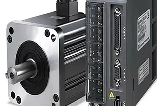
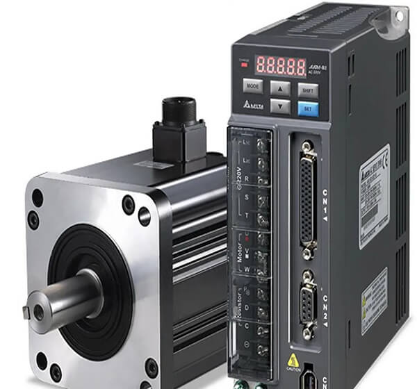
Servo motors are widely used in automated equipment, especially for position control. Most servo motors from various brands have this capability.
The controller sends pulses to control the servo motor’s operation, with the number of pulses determining the rotation angle and the pulse frequency determining the speed (which is related to the electronic gear setting).
When a new system’s parameters don’t work, start by setting the position gain to ensure that the motor operates as smoothly as possible without noise. The moment of inertia ratio is also critical. It can be referenced by the number set through self-learning, then set the speed gain and speed integration time to ensure low-speed, continuous operation and controlled position accuracy.
(1) Position proportional gain
Set the proportional gain of the position control regulator. The higher the gain, the greater the stiffness, and the smaller the position lag under the same frequency command pulse. However, setting it too high may cause oscillation or overshoot. The parameter value is determined by the specific servo system model and load.
(2) Position feedforward gain
Set the feedforward gain of the position control. When the set value is larger, the position lag under any frequency command pulse is smaller, the feedforward gain of the position loop is higher, and the high-speed response characteristics of the control system are improved. However, this may cause instability and oscillation in the system. When high response characteristics are not necessary, this parameter is usually set to 0, with a range of 0-100%.
(3) Speed proportional gain
Set the proportional gain of the speed regulator. The value of the gain increases with a higher setting, making the system stiffer. The value of the parameter should be determined based on the specific servo drive system model and load. Generally, the greater the load inertia, the higher the set value. Attempt to set a larger value while ensuring that the system does not produce oscillation.
(4) Velocity integral time constant
Set the integral time constant of the speed regulator. The smaller the setting value, the faster the integration speed. The parameter value is determined based on the specific model and load of the servo drive system. In general, the greater the load inertia, the larger the set value. Under the condition that the system does not generate oscillation, aim to set a smaller value.
(5) Velocity feedback filter factor
Set the speed feedback low-pass filter characteristics.
The higher the value, the lower the cut-off frequency and the lower the noise generated by the motor.
If the load inertia is large, the set value can be increased appropriately.
If the value is too high, the response will be slow, which may cause oscillation.
The lower the cutoff value, the faster the response.
If higher speed response is required, the set value can be reduced appropriately.
(6) Maximum output torque setting
Set the internal torque limit value of the servo driver.
The setting value is expressed as a percentage of the rated torque.
This limit is always in effect and sets the range of positioning completion pulses in position control mode.
This parameter provides a basis for the driver to determine if positioning is complete under position control mode.
When the number of remaining pulses in the position deviation counter is less than or equal to this parameter’s set value, the driver considers the positioning to be complete, and the in-place switch signal is on. Otherwise, it is off.
In position control mode, the positioning completion signal is output, and the set value of the acceleration and deceleration time constant determines the acceleration time of the motor from 0 to 2000 RPM or the deceleration time from 2000 to 0 RPM.
The acceleration and deceleration characteristics are linear, and the arrival speed range is set. In non-position control mode, if the servo motor’s speed exceeds the set value, the speed arrival switch signal is on, otherwise it is off.
This parameter is not used in position control mode and is independent of the direction of rotation.
(7) Manually adjust the gain parameters
Adjust the Speed Proportional Gain KVP Value
After the servo system is installed, the parameters must be adjusted to ensure stable rotation. Start by adjusting the speed proportional gain KVP value. Before making any adjustments, set the integral gain KVI and differential gain KVD to zero, then gradually increase the KVP value. Observe if there is any oscillation when the servo motor stops and manually adjust the KVP parameters to see if the rotation speed is noticeably fast or slow. If the KVP value causes the above-mentioned issues, reduce the KVP value to eliminate oscillation and stabilize the rotation speed. This value will be the preliminary determined parameter value. Repeat the correction process as needed to achieve the ideal value.
Adjust the Integral Gain KVI Value
Gradually increase the KVI value of the integral gain to produce the integral effect. As mentioned in the introduction to integral control, the KVP value and integral effect can cause oscillation and instability when they reach critical values. Similarly, reduce the KVI value to eliminate oscillation and stabilize the rotation speed. This value will be the preliminary determined parameter value.
Adjust the Differential Gain KVD Value
The main purpose of differential gain is to smooth the speed rotation and reduce overshoot. Gradually increasing the KVD value will improve speed stability.
Adjust the Position Proportional Gain KPP Value
If the KPP value is adjusted too much, the motor positioning will overshoot, causing instability. In this case, reduce the KPP value to reduce the overshoot and avoid instability, but be careful not to adjust it too small, as it will reduce positioning efficiency.
(8) Automatically adjust gain parameters
Modern servo drivers are computerized and most of them offer an automatic gain adjustment feature, which can handle most load conditions. During parameter adjustment, you can first use the automatic parameter adjustment function and then make manual adjustments if necessary. The automatic gain adjustment also has various options. Typically, the control response is divided into different levels, such as high, medium, and low response, and users can set it according to their requirements.