Exploring Flanging Die Designs: A Guide to Typical Structures
Have you ever wondered how intricate metal parts are made with precision? This article explores the fascinating world of thread tapping and flanging dies, revealing the secrets behind their design and operation. You’ll learn how these tools shape metal with accuracy and efficiency, making everyday objects possible.
For small-sized threads, a piercing punch is generally used in thread tapping dies, while for larger threads (M5 and above), a punch with a prefabricated hole is commonly employed, allowing for punching and tapping to be completed in one go.
When the punch descends to a set height, the material is torn under the action of the planar cutting edge. In most cases, the scrap material from the punching process remains attached after tapping but will detach on its own after threading, as shown in Figure 5-20.
Figure 5-20: Flanging Punch for Small Thread Sizes (M4 and below)
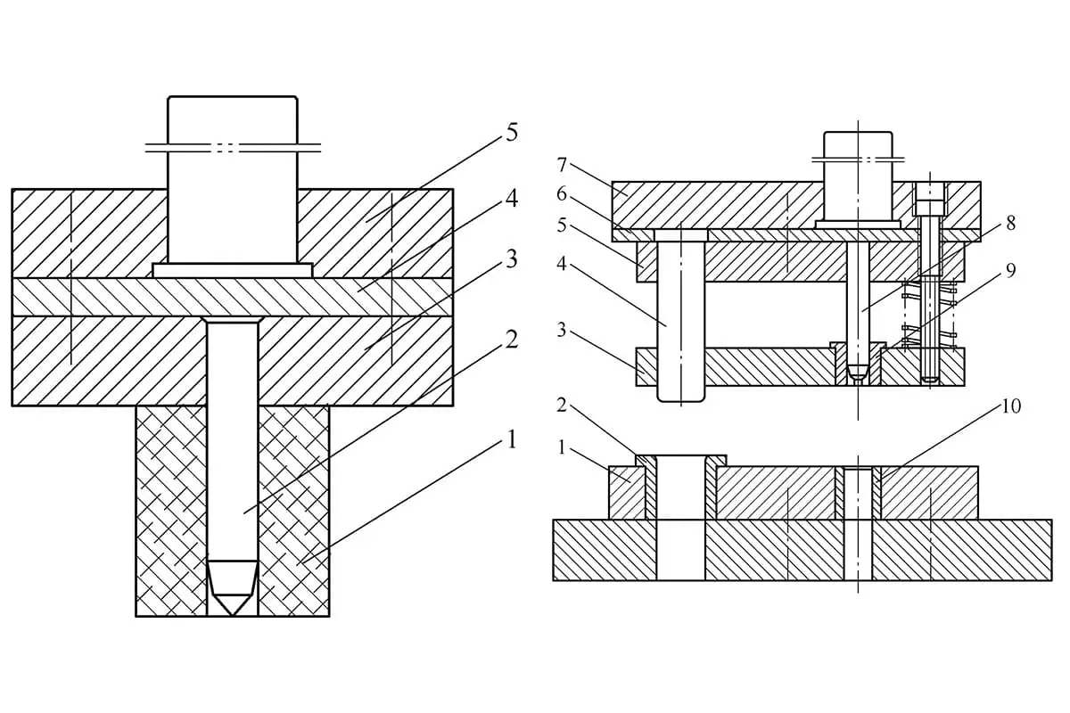
When flanging multiple holes simultaneously on the secondary die, guide posts and bushings should be installed, as illustrated in Figure 5-21.
Figure 5-21 Flanging Die with Multiple Holes for Large Threads (M5 and above)
1—Die 2—Guide Bushing 3—Stripper Plate 4—Guide Post 5—Punch Retainer Plate 6—Spacer Plate 7—Upper Die Shoe 8—Punch 9—Guide Sleeve 10—Die Insert with Hard Alloy
For large-diameter single-hole flanging dies with prefabricated holes, guide posts and bushings are not required. Centering is achieved by aligning the guiding section of the punch with the prefabricated hole, followed by positioning according to the external shape of the workpiece, as depicted in Figure 5-22.
Figure 5-22: Large Hole Flanging Die
1—Die insert 2—Workpiece 3—Die insert liner 4—Ejector ring 5—Upper die shoe 6—Punch 7—Lower die shoe
Flanging and tapping dies should generally be equipped with an ejector mechanism to disengage the workpiece from the punch. The workpiece can easily be removed from the die under the action of the rebound force, hence there is usually no need to consider using a stripper.
However, when performing extensive deformation thinning taps or when the material thickness is ≥4mm, the use of a stripper should be considered, as shown in Figure 5-23.
Figure 5-23: Thinning Flanging Die
1—Punch 2—Edge Pressing Ring 3—Die 4—Lifter.
Asymmetric Force Flanging Die (Chrysanthemum Pot Flat Handle)
In theory, asymmetrically loaded flanged parts and asymmetrically bent parts can be processed into symmetrical parts to prevent the workpiece from moving, by completing both parts at the same time, and then cutting the workpiece in half after flanging.
However, since small parts like pot handles are often cut from the excess material at the edges, which does not meet the above conditions, this description focuses primarily on individual flanging dies.
During the single bend process, the material is pulled by the unilateral flanging force, resulting in slippage. The key to designing such dies lies in preventing material slippage and ensuring that the flange line is correctly positioned.
Before the punch contacts the workpiece, use a movable pressure plate to clamp the workpiece firmly. The clamping force must exceed the flanging force.
Incorporating various compensation factors, the formula for estimating the flanging force of stainless steel materials is as follows:
In the formula:
F – flanging force (N);
L – the length of the flange line (mm);
t – material thickness (mm);
Rel. – yield strength, which is set at 280 (MPa).
Currently, most of these types of molds predominantly use rubber elastomers as the elastic element for applying pressure. Rubber elastomers offer significant benefits such as high elasticity, excellent recovery performance, and tear resistance.
The thickness of the rubber elastomer is not necessarily better when increased; an optimal thickness is generally three to four times the sum of the flange height plus a certain allowance.
If the pressure within the calculated height is insufficient, thinner rubber sheets can be layered, with thin steel shims sandwiched in between. Increasing the surface area of the rubber can enhance the pressure applied. For punched parts with holes, it is best to use hole positioning as shown in Figure 5-24.
Figure 5-24: Chrysanthemum Pot Flat Handle Hemming Die Assembly
1) Rubber Elastomer, 2) Force Transmission Pin, 3) Locating Plate, 4) Punch, 5) Blanking Plate, 6) Die, and 7) Lower Die Holder.
The spout of the persimmon-shaped pot features a rolled edge
During the brazing process between the spout and the body of a persimmon-shaped pot, to conserve expensive silver brazing material, it is necessary to form a vertical flange along the contour line of the larger end of the pot’s body. The flanging operation at the spout is performed on a cantilever-style workbench press, with the die set in an inverted position, as shown in Figure 5-25.
Figure 5-25 illustrates the kettle body and spout flanging process
During operation, place the pre-punched kettle body 1 onto the punch die 5 with positioning features. As the die 4 descends, it overcomes the resistance of the spring element 6 to flange the workpiece. When the upper die ascends, the lifting plate 3 is raised by the spring force, releasing the workpiece from the flanging position.
In the design phase, it is critical to ensure that the vertical distance between the kettle spout and the cantilevered workbench exceeds the flanging stroke to prevent damage to the spout.
Flanging instead of curling (flanged spout of a kettle)
In the production of stainless steel kettles, the spout is commonly processed using a double flanging technique as shown in Figure 5-26. During design, the height of the first flange should be moderate, ranging from 4 to 6 times the material thickness. The height of the second flange should not be too small and should range from 8 to 12 times the material thickness.
At this stage, the clearance on both sides of the punch and die should be increased to 1.5 to 2 times the material thickness. During the second flanging process, the edge formed by the first flange will automatically press tightly against the second flange, creating an effect similar to a crimped edge.
Figure 5-26: The kettle spout’s flanged edge as a substitute for the curled edge.
1. The effect after punching the body of the kettle. 2. The first flanging. 3. The second flanging.
Hard die edge flanging
Figure 5-27 illustrates a flanged piece with a rounded arc, with a material thickness of 1.0mm and a flange height of 12mm. Based on experience, to prevent wrinkling under compression, the flange height H should not exceed 14 times the thickness (H≤14t). The forming die is shown in Figure 5-28.
Typically, to enhance operational reliability, the punch arc should be slightly longer than that of the workpiece, with the lower die being 6 to 10mm wider than the upper die.
The die insert (3) can be made of low-carbon steel. The working surface of the wear plate (9) is rounded to primarily serve the function of the die corner radius (R). Processing it as a separate component can reduce the consumption of die steel or high-speed tool steel, decrease manufacturing difficulty, and allow for fine adjustment of the clearance between the punch and die.
The punch and stripper plate are matched to the product drawing. The working edge of the wear plate is parallel to the die shoe. The material is gradually formed during the downward stroke and ultimately ejected from the cavity by the stripper plate.
Figure 5-27: Arc Flanged Component
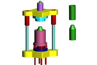
Tube Flaring with a Cantilevered Punch and Ball Method
The tube can be flared outward by using a cantilevered punch with a steel ball. The schematic of the mold structure is shown in Figure 5-29, which is suitable for flanging after a prefabricated hole has been processed on the tube material.
The working process of the mold is as follows:
First, place a steel ball of the appropriate diameter inside the tube at the punching (drilling) location, then lay the tube flat, fit the punch over it, and press down on the steel ball. At this point, start the press machine, and as the upper die moves downward, it forces the punch to move down, pushing the steel ball through the tube.
After the upper die returns, the punch automatically lifts, is removed from the tube, and thus the entire flanging process is completed.
The structure of this mold is simple and is virtually unrestricted in the length direction, but the cantilever strength of the mold is limited by the inner diameter of the steel tube. Flanging can be performed on thicker tubes with an inner diameter of 40mm or larger.
In this design, a rubber elastomer is added beneath the upper die to reduce noise; and the limit screw can be adjusted to set the height of the punch.
Figure 5-28: Arc Flanging Part Formation
1. Ejector Mechanism 2. Lower Die Base 3. Die Insert 4. Locator 5. Punch 6. Upper Die Base 7. Punch Retainer Plate 8. Stripper Plate 9. Hard Plate
Quick-change mandrel for converting internal diameters to external diameters, featuring a metal mesh cladding ring
Figure 5-30 illustrates a skimmer net mouth forming die, which can also be used to fabricate the wrapping rings for metal mesh sheets of other cylindrical components, such as engine air filters.
The main parts of the die consist of an expansion cone (8), expansion blocks (4), return springs (3 and 6), and a lower die base (1).
The expansion blocks are sized according to the inner diameter of the workpiece after forming. They are made from material that has been heat-treated and then machined.
These blocks are divided into equal sections and specific gaps are cut to ensure that, once contracted, they maintain a reasonable clearance with the prefabricated ring. Return springs (3 and 6) tighten the expansion blocks (4) when they are in a free state.
When the prefabricated ring (5) is fitted over the expansion block (4), the die is in the reset position, and the outer diameter of the expansion block (4) is smaller than the inner diameter of the prefabricated ring (5).
As the upper die moves downward, the press block (7), driven by the strong spring (10), overcomes the upward force of spring (2), forcing the expansion block (4) to move downward and expand outward, increasing its outer diameter until it fits snugly against the inner diameter of the workpiece. When the expansion block has descended fully, its outer diameter ceases to increase.
The upper die continues to move down, pushing the prefabricated ring (5) into the R-groove to gradually form it. The compressed material flows upward along the outer diameter of the upper die, forming a new outer diameter, and creating a designated clearance with the original diameter to accommodate the metal mesh sheet.
As the upper die rises, the workpiece remains on the lower die, and the expansion block, under the combined action of spring (2) and return springs (3 and 6), contracts in diameter, facilitating the removal of the workpiece.
By adding or removing shims (not shown in the diagram) beneath the support plate (12) or the expansion cone (8), the diameter of the expansion blocks can be adjusted.
This die operates reliably and does not require high-quality blanks; it can even be used with lap-welded material rings.
Figure 5-30 Quick-Change Mold for Internal to External Diameter Conversion
1 Base, 2 Springs, 3 & 6 Return Springs, 4 Expansion Blocks, 5 Preformed Rings, 7 Clamping Blocks, 8 Expanding Mandrels, 9 Upper Mold Base, 10 Heavy-Duty Springs, 11 Upper Mold, 12 Support Plate, 13 Spring Center Pin
Top and Bottom Flanging Die
Figure 5-31 illustrates a top and bottom flanging die suitable for thick material flanging.
Tube End Flanging Forming
Tube end flanging forming is a specialized forming process that evolved from traditional stamping flanging techniques. It involves applying axial pressure to the tubing through a die to induce localized bending deformation at the edge of the tube mouth.
This technique allows for the manufacturing of parts with the advantages of simplicity, fewer processing steps, lower cost, and high quality, and it can even produce parts that are difficult to achieve with other stamping methods. This process has been widely adopted in industrial sectors such as automotive and aerospace.
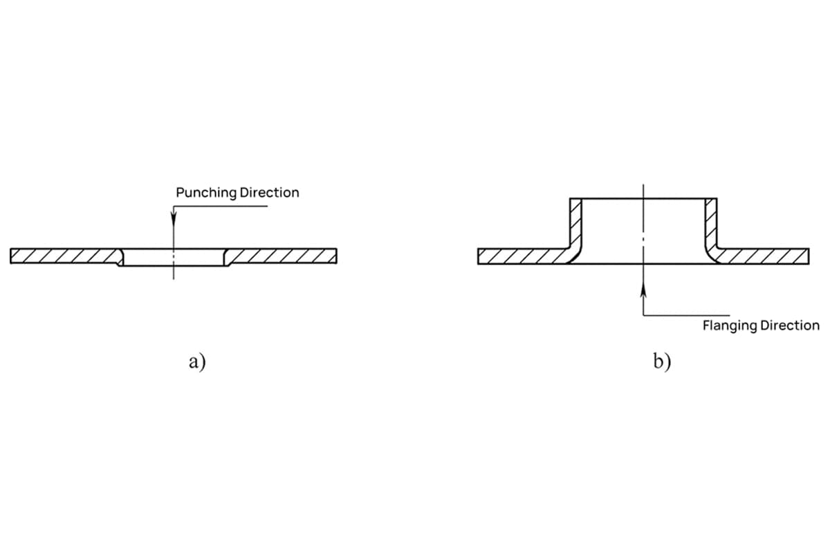
There are two basic methods of tube end flanging forming: external flanging and internal flanging, as shown in Figure 5-32.
a) and b) External Flange; c) and d) Internal Flange. 1. Tube Blank 2. Guide Ring 3. Tapered Die 4. Fillet Die.
The tube rolling process not only effectively forms a variety of double-walled cylindrical tubes and multi-layered tube components but also processes convex-bottomed cups, stepped tubes, special-shaped tubes, as well as half-wall double tubes, annular double-wall cylinders, hollow double-wall nuts, heat exchangers, automotive mufflers, and waveguides used in the electronics industry.
Currently, these components are generally manufactured using multi-step stamping and welding methods, which are difficult, costly, and yield poor surface quality. The rolling process ensures the reliability, light-weight, and material savings for these parts.
A wide range of tubular materials is suitable for the rolling process, including aluminum alloys, low carbon steel, and austenitic stainless steel. Tubes ranging from 5mm x 0.5mm to 250mm x 5mm in size can be successfully rolled into double-layered tubes.
Figure 5-33: Parts formed by the roll forming process
a) Cone-shaped die rolling tube, b) Tube rolling + rolling, c) Tube rolling + flaring, d) Stretch rolling tube.
Tube spinning is a complex deformation process that involves transitioning from flaring deformation to curling deformation, and then to spinning deformation. To ensure a smooth transition between deformation modes, it’s essential to satisfy the mechanical, geometrical, and plasticity conditions during deformation. The primary process parameters include the spinning force, die semi-cone angle, tube’s relative wall thickness, and the tube material’s plasticity conditions.
1) Outward Spinning
Under axial pressure, the tube blank spins from inside to outside, turning the tube’s inner wall into the outer wall. This process increases the tube diameter. Although the external pressure load thickens the tube wall slightly, the circumferential tensile stress produced by the outward spinning is stronger, leading to a thinner tube wall.
The mold types for outward tube spinning mainly include conical dies, annular groove dies, and stretch spinning dies. When processing double-layered tubes using conical or annular groove dies, the upper part of the mold not only applies pressure to the tube material but also needs to be equipped with a guide ring to direct the material that has already been spun.
a) Conical Die.
The conical die is the most representative type of spinning die. When designing a conical die, the primary consideration is determining the semi-cone angle (a) to satisfy the conditions for spinning. Based on stress-strain and plasticity calculations and considering the influence of the material’s elongation, the semi-cone angle (a) should meet the following condition: 22.5° ≤ a ≤ 55°.
Similar to tube flaring, the maximum outer diameter of the spun tube is also limited by the material’s elongation rate. In principle, the spinning diameter size can be freely chosen between the material’s elongation rate and the minimum curling radius.
When a large difference in diameter is required before and after spinning, a larger semi-cone angle should be used. Conversely, a smaller semi-cone angle should be selected when a smaller diameter difference is needed.
Conical dies are versatile, have low friction, simple structures, and are easy to manufacture. However, when the tube blank deforms on a conical die, it tends to slide, making accurate centering difficult.
The spinning is in a free deformation state, determined only by the principle of minimum resistance and stress balance, and is significantly affected by the non-uniformity of the material structure, making it challenging to produce high-quality tubular components. To prevent the tube end from sliding on the cone die, a cylindrical guide feature can be added to the cone head, resulting in a noticeable improvement, as shown in Figure 5-34a.
Figure 5-34 Flaring Die Types
a) Locating Conical Die b) Grooved Radius Die c) Stretch Flaring Die
(b)Annular Groove Radius Mold.
The radius corner groove die is a type of tube flaring die derived from the tube end flanging (flanging) die. On a conical die with a positioning boss, the intersection of the boss and the conical surface is made into a conical transition to facilitate the curling and deformation of the tube blank. This die features excellent centering properties.
As the tube material is flared, it is constrained by the radius r of the circular groove, resulting in consistently high-quality tube components, as shown in Figure 5-34b.
The design of the radius corner groove die primarily involves determining the radius r of the circular groove. The size of r not only dictates the restraining effect on the deformation of the tube blank at the radius corner but also determines the geometric interference between the flare and the undeformed part of the tube blank.
Therefore, it is a critical process parameter that must be greater than or equal to the material’s minimum bending radius and less than or equal to the permissible radius based on the material’s elongation rate.
When designing the radius corner groove die, it is not necessary to calculate the radius r. Instead, it can be provided based on experience and the dimensions indicated on the drawing.
For stainless steel tubing, the minimum bending radius is typically
R=3t
where t is the thickness of the material.
The maximum tube flaring diameter for general tubing is
d=D(1+1.4A)
And for welded tubing, the maximum tube flaring diameter is
d=D(1+1.3A)
where:
d – the tube flaring diameter (mm)
D – the tube blank diameter (mm)
A – the material’s elongation rate (%)
(c) Stretch flanging die.
When performing tube flanging with the aforementioned mold types, defects such as instability-induced wrinkling or bending of the flanged section can occur. This is because the tube blank is under compressive stress during deformation. In contrast, the stretch flange mold places the deforming section of the tube blank under tensile stress when subjected to external load, thereby completely eliminating the wrinkling phenomenon during flanging.
Moreover, the deformation zone is determined by the shape of the mold, allowing the dimensional accuracy of the workpiece to be fully controlled by the mold. Therefore, for tubular components with stringent dimensional accuracy requirements, a stretch flange mold should be used.
To reduce frictional resistance in the already flanged section, the working length of the mold’s outer diameter should be between 8 and 12mm, with the remaining sections hollowed out as shown in Figure 5-34c.
Before the stretch flange mold begins operation, the end of the tube is first expanded into a flange face to serve as a clamping surface during stretching. Consequently, the outer diameter of the tube formed by the stretch flange mold is always smaller than the maximum outer diameter permitted by the material’s elongation rate.
(2) Inward Flanging
During inward flanging, the tube blank is rolled from the outside in, resulting in a smaller external diameter after forming.
1) Hard Die Inward Flanging.
Hard die inward flanging is rarely used in production practices. This is because inward flanging is much more difficult compared to outward flanging.The forming process of inward flanging is one where the material continually thickens.
During this thickening process, the material’s crystal lattice must be rearranged. The force required for the rearrangement of the crystal lattice is more than four times greater than the tensile stress needed for the material to elongate (tensile strength).
Since the material’s yield strength is always less than the force needed for lattice rearrangement, the tube material becomes unstable and wrinkles before it even enters the flanging process, making it impossible to complete the inward flanging.
In fact, there are many alternative techniques to inward flanging, including using smaller diameter tubes for outward flanging, roller hemming, and reducing the diameter by cutting followed by inward stretching and flanging (see Figure 7-21).
Among the aforementioned methods, the most commonly used is the outward flanging of small diameter tubes, which involves using the inner diameter size of the blank tube as the required inner diameter size of the tube component, while the size after outward flanging becomes the component’s diameter.
2) Roller Inward Flanging.
When using rollers for inward flanging, there are certain limitations between material thickness and diameter, specifically a ratio of D/t ≥ 200 is required for the process to proceed smoothly. Otherwise, the resistance caused by material aggregation can be excessive, resulting in a polygonal external diameter of the workpiece.
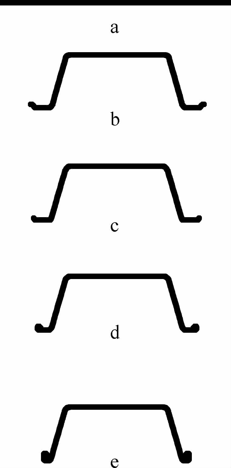
Figure 5-35: Bucket Forming Process
a) Blanking of the circular sheet b) Drawing c) Trimming d) Flanging e) Hemming
Bowl Forming Process
A bowl is essentially an enlarged version of a basin designed to increase capacity. To enhance its strength, a flanging step is added to the rolled edge, as depicted in Figure 5-35.
The rolling process is strategically placed before flanging to prevent wrinkling of the flange. While the deformation mechanism of the rolled section during flanging is not yet fully understood, it has proven to be practically effective.
As the founder of MachineMFG, I have dedicated over a decade of my career to the metalworking industry. My extensive experience has allowed me to become an expert in the fields of sheet metal fabrication, machining, mechanical engineering, and machine tools for metals. I am constantly thinking, reading, and writing about these subjects, constantly striving to stay at the forefront of my field. Let my knowledge and expertise be an asset to your business.
Have you ever wondered how to calculate the deformation in hole flanging? Understanding flanging coefficients is crucial for precision in metalworking. This article dives into the key factors influencing these…
Ever wondered how everyday objects are shaped with precision? This article explores the fascinating world of joint construction stamping technology. You'll learn about the process, from obtaining technical drawings to…
Intrigued by the marvels of metal stamping? In this blog post, we dive into the fascinating world of hole flanging, necking, and bulging. Our expert mechanical engineer will guide you…
Have you ever considered the game-changing potential of servo press technology in manufacturing? In this article, we'll explore how these advanced machines are revolutionizing the industry, offering unparalleled precision, efficiency,…
Choosing the right hydraulic press can be daunting given the wide range of options. What are the critical factors to consider for your specific needs? This article guides you through…
Have you ever wondered how massive metal parts are shaped with precision? This article explores the fascinating world of hydraulic presses, detailing their applications, features, and intricate workings. Learn how…
Have you ever wondered how cars are made so quickly and safely? This article unveils the magic behind automated stamping production lines, where robots replace manual labor, boosting efficiency by…
Imagine boosting your factory's efficiency with a perfectly designed stamping workshop. This article dives into the essentials of planning such a workshop for automobile parts, from equipment selection to layout…
Are you struggling to cut down on stamping production costs without sacrificing quality? This article delves into practical strategies to help you do just that. From optimizing material usage to…