Hole Flanging Coefficients: Your Guide to Accurate Calculations
Have you ever wondered how to calculate the deformation in hole flanging? Understanding flanging coefficients is crucial for precision in metalworking. This article dives into the key factors influencing these coefficients, from material properties to hole processing methods. By reading further, you’ll grasp the essentials needed to achieve accurate flanging results, ensuring your projects maintain structural integrity and meet high standards. Discover practical insights and improve your metal fabrication skills today.
The degree of deformation in flanging or flanging operations is commonly represented by the flanging coefficient, which is calculated using the following formula:
In the formula:
K-the flanging coefficient;
D0 – the pre-punched hole diameter in millimeters (mm);
d – the average diameter of the straight edge after flanging (mm).
The higher the value of K, the less deformation occurs; conversely, the lower the value of K, the greater the deformation.
The primary factors affecting the flanging coefficient are as follows:
1. The properties of the material; the better the plasticity, the smaller the K value can be.
2. The relative diameter of the pre-punched hole, t/D0; the smaller the t/D0 value, the larger the K value.
3. The method of hole processing; drilled holes, due to the absence of a tear surface, are less likely to crack during flanging. Punched holes, having some tear surfaces, are prone to cracking, thus requiring a larger K value. If the material is annealed after punching or if the hole is finished, a flanging ratio close to that of drilled holes can be achieved.
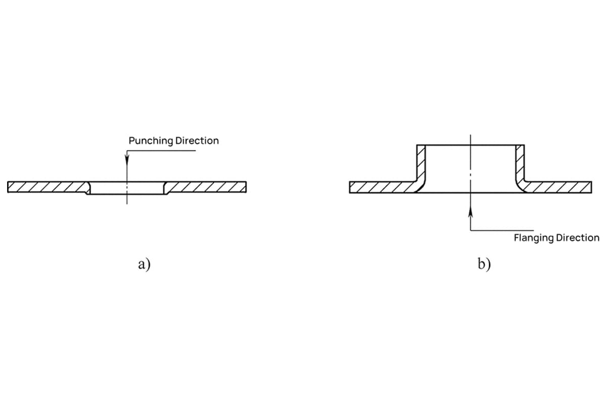
Additionally, reversing the direction of the punching relative to the flanging direction, with the burrs located on the inside of the flange, can reduce cracking, as shown in Figure 5-4.
Figure 5-4 Counter-direction of Piercing and Flanging a) Piercing b) Flanging
4. When using a spherical, parabolic, or conical punch for piercing, the edges of the hole are smoothly and gradually flared, reducing the K-factor and increasing the degree of deformation. The limit piercing coefficient for low carbon steel is shown in Table 5-1, and the piercing coefficients for various materials are listed in Table 5-2.
5-1 The ultimate piercing coefficient for low-carbon steel.
Pilot punch profile
Hole Machining Methods
Material relative thickness, d0/t
100
50
35
20
15
10
8
6. 5
5
3
1
Spherical punch
Deburr after drilling.
0.70
0.60
0.52
0.45
0.40
0.36
0.33
0.31
0.30
0.25
0.20
Punch holes with a punching die.
0.75
0.65
0.57
0.52
0.48
0.45
0.44
0.43
0.42
0.42
—
Cylindrical Punch
Deburr after drilling.
0.80
0.70
0.60
0.50
0.45
0.42
0.40
0.37
0.35
0.3
0.25
Punch holes with a punching die.
0.85
0.75
0.65
0.60
0.55
0.52
0.50
0.50
0.48
0.47
—
Note: Utilizing the limit flanging coefficient from this table may result in minor cracking at the edge of the hole after flanging. If the workpiece cannot tolerate cracking, the flanging coefficient should be increased by 10% to 15%.
5-2 Various Materials’ Flanging Ratios
Annealed raw material
Hole Flanging Ratio
K0
Kmin
Galvanized steel sheet (white iron)
0. 70
0. 65
Soft steel
t = 0. 25 ~ 2. 0mm
0. 72
0. 68
t =3. 0 ~ 6. 0mm
0.78
0.75
Brass H62, thickness ranging from 0.5 to 6.0 mm
0. 68
0. 62
Aluminum, thickness ranging from 0.5 to 5.0 mm
0.7
0. 64
Hard aluminum alloy
0. 89
0. 80
Titanium alloy
TA1 (Cold State)
0. 64 ~ 0. 68
0. 55
TA1 (Heated to 300-400°C)
0. 40 ~ 0. 50
–
TA5 (Cold State)
0. 85 ~ 0. 90
0.75
TA5 (Heated to 500-600°C)
0. 70 ~ 0. 65
0.55
Stainless steel, high-temperature alloys
0. 69 ~ 0. 65
0. 61 ~ 0. 57
When minor cracking is permissible in the flanging process, the minimum numerical value K may be utilized.
As the founder of MachineMFG, I have dedicated over a decade of my career to the metalworking industry. My extensive experience has allowed me to become an expert in the fields of sheet metal fabrication, machining, mechanical engineering, and machine tools for metals. I am constantly thinking, reading, and writing about these subjects, constantly striving to stay at the forefront of my field. Let my knowledge and expertise be an asset to your business.
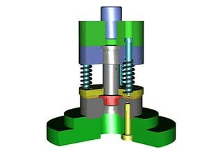
Have you ever wondered how intricate metal parts are made with precision? This article explores the fascinating world of thread tapping and flanging dies, revealing the secrets behind their design…
Intrigued by the marvels of metal stamping? In this blog post, we dive into the fascinating world of hole flanging, necking, and bulging. Our expert mechanical engineer will guide you…
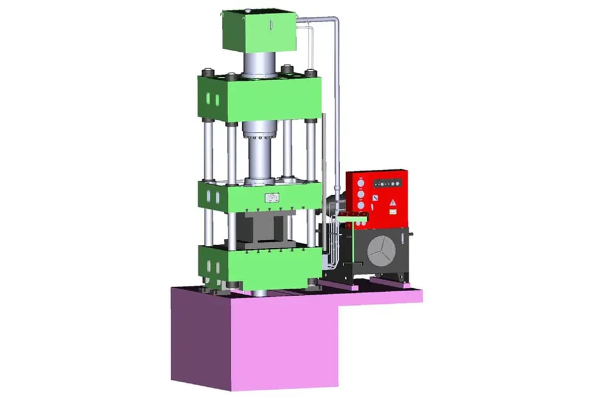
Choosing the right hydraulic press can be daunting given the wide range of options. What are the critical factors to consider for your specific needs? This article guides you through…
Have you ever wondered how massive metal parts are shaped with precision? This article explores the fascinating world of hydraulic presses, detailing their applications, features, and intricate workings. Learn how…
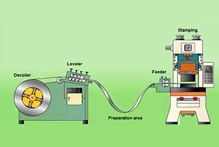
Have you ever wondered how cars are made so quickly and safely? This article unveils the magic behind automated stamping production lines, where robots replace manual labor, boosting efficiency by…
Have you ever wondered how a flat sheet of metal can be transformed into a complex, hollow part? Deep drawing, a fascinating forming process, makes this possible. In this article,…
Have you ever wondered about the incredible power of hydraulic presses? These marvels of engineering can exert immense force, transforming materials in ways that seem almost magical. In this blog…
Ever wondered how everyday objects are shaped with precision? This article explores the fascinating world of joint construction stamping technology. You'll learn about the process, from obtaining technical drawings to…