
Top 15 Best Stamping Press Manufacturers & Brands in World
Have you ever wondered how the machines that shape our world are made? This blog takes you on a journey through the top punch press machine manufacturers. You'll learn about…
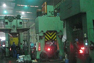
Have you ever wondered how massive metal parts are shaped with precision? This article explores the fascinating world of hydraulic presses, detailing their applications, features, and intricate workings. Learn how these powerful machines transform metal with ease and precision, and discover the technology behind their impressive capabilities.
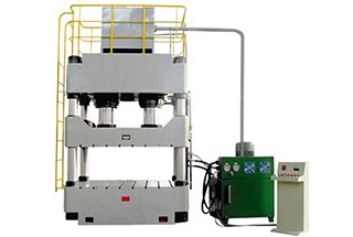
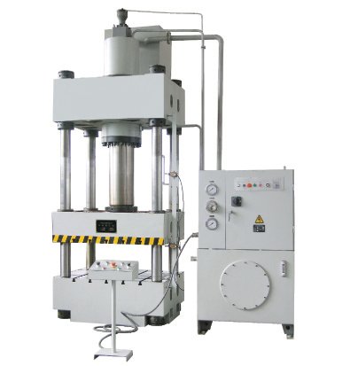
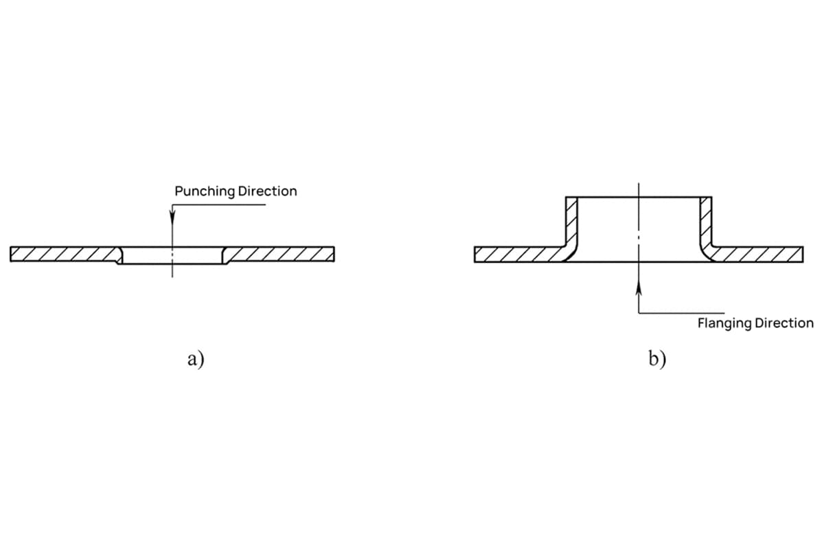
This hydraulic press machine is suitable for all types of metal material suppression processes, including punching, bending, flanging, and more. Additionally, it can be used for the calibration, pressing, and forming of metal products.
The hydraulic press has an independent power supply and electrical system, and it uses a button for common control. Its operations are managed by a PLC programmable controller, allowing for adjustment and semi-automatic operation.
The working pressure, pressing speed, and travel range of this hydraulic press can be customized based on specific technological needs.
This hydraulic press machine comprises a master motor and control mechanism, integrated through pipelines and electric devices.
The main motor includes a machine frame, master cylinder, stroke limiting device, and more.
The control mechanism comprises a hydraulic pump station (power system) and an electric cabinet.
The structure and functions of the aforementioned parts are as follows:
The hydraulic press machine frame
The machine frame primarily comprises a beam, workbench, hydraulic pad, slider, vertical columns, and tight nuts.
The regulation nut, four basic columns, upper beam, and workbench are firmly secured at both ends of the machine frame via locking nuts, with the slider situated at its center.
Accuracy is adjusted using the regulation nut and locking nut that are fixed onto the beam.
The slider and piston rod of the master cylinder are connected by locking nuts and rely on the four columns for up and down movement. Both the slider and movable workbench are equipped with T-channels, which facilitates the installation of dies.
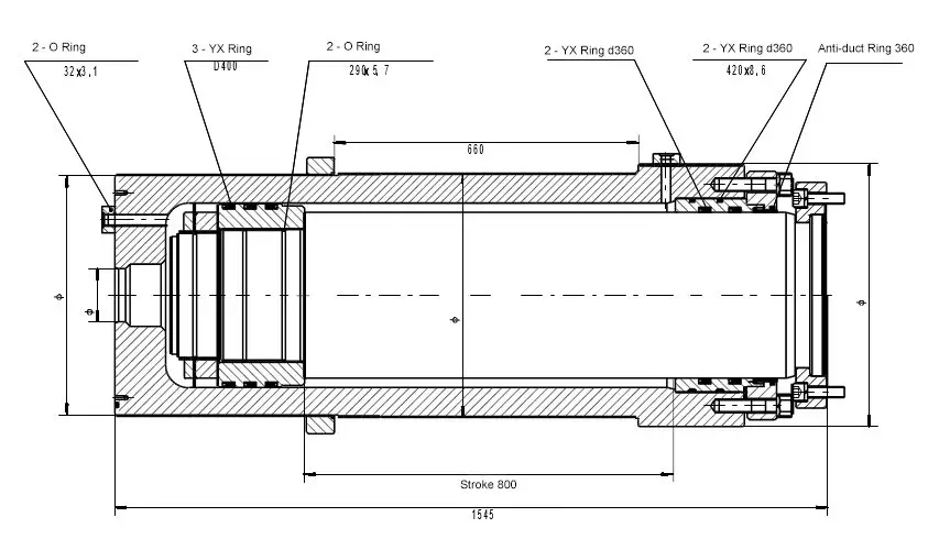
Master Cylinder
The master cylinder is secured to the upper beam through cylinder shoulders and large locking nuts.
The piston’s bottom end connection features a flange, screw, and slider, while the piston heads are made of cast iron and equipped with a reverse sealing ring on the outside and an “O” shaped sealing ring on the inside to form two oil chambers.
The cylinder opening is also equipped with sealing rings and fastened by flanges to ensure the sealing of the lower chambers. Both the upper and lower sides of the flange are also equipped with a sealing ring.
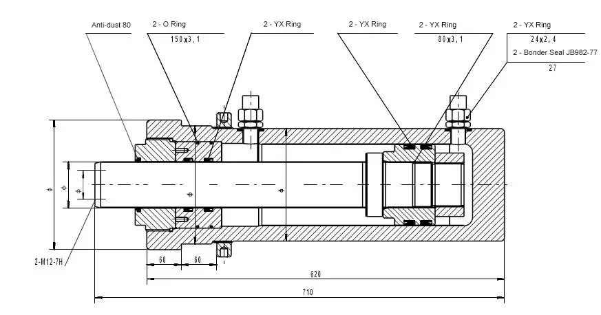
Hydraulic pad
The hydraulic pad is installed in the workbench and fixed with the top cylinder using a locking nut, enabling up and down movement. The structure of the top cylinder is the same as that of the master cylinder.
Electric cabinet
The electric cabinet can be moved freely and features buttons, time relays, and an auto switch on its surface.
Stroke limiting device
The stroke limiting device is located on the right side of the machine and comprises a bracket, ram, limit switch, and more. The slider can be adjusted by altering the position of the ram.
Hydraulic pump station (power system)
The hydraulic pump station comprises an oil tank, high-pressure pump, motor, cartridge valve, and more. The tank is welded and features a filter screen inside.
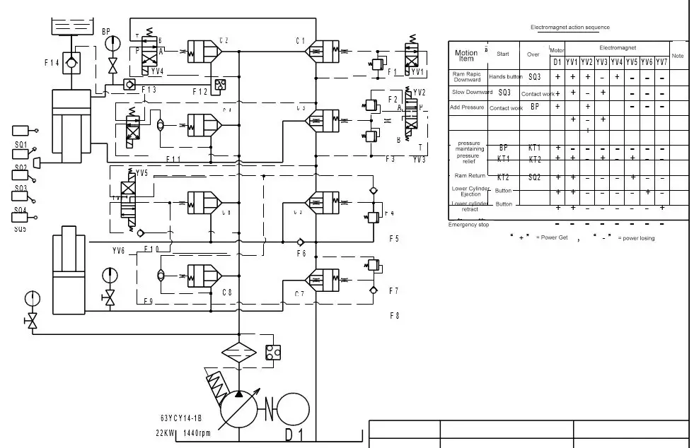
The hydraulic system theory is shown in the attached hydraulic theory drawing and action sequence list. Let’s use the semi-auto working cycle as an example to demonstrate the hydraulic theory:
First, connect the power and press down SB3 and SB5 to start the motor.
At this point, all electric valves are still on idle states, and the oil flowing out from the high-pressure pump will flow back to the oil tank. The system is in a no-load cycling circulation state.
With both hands, press down SB6 and SB7. At this time, solenoids YA1 and YA5 will be powered on, and oil coming from the high-pressure pump flows into the upper chamber of the master pump. YA5 being powered on will make valve 11 connect together with P and B, A and T. Oil in the lower chamber will flow back to the oil tank through valve 11, and the slider on a no-supporting state will quickly move downward due to its self-weight.
At this time, the oil in the pump is incompetent to supplement the upper chamber of the master cylinder and form negative pressure, which will suck the oil-infusing valve open, making oil in the oil-supplying drum infuse into the master cylinder’s upper chamber heavily. Therefore, the slider will quickly run down.
When the slider runs down and approaches the SQ2 switch, the switch will release signals for continuing power YA1 and cut off YA5. Then the oil must overcome supporting valve pressure before returning back to the oil tank, and the lower chamber will form reverse pressure, reducing the descending speed. Therefore, the slider cannot descend relying on its self-weight and slows down.
When the slider runs down and touches the workpieces, and the system pressure increases up to the prescribed pressure in pressure gauge SPI, the system will give out the signal to discharge the solenoid. The pump will enter into a no-load circulation state, and time relay KT1 will connect and enter into a press-holding time-delay condition.
When the time-delay increases up to the pre-setting time, delay contacts KT1 release signal to power YA2 and YA6, and the low-pressure valve adjusts the system oil and generates pressure. The system will be on the low-pressure state, and the pump oil will open the unloading valve on the infusing valve, unloading the high-pressure oil in the upper chamber.
During the time, put through the time relay KT2 and begin time-delay unloading.
When KT2 pre-setting time for pressure relief comes to end, KT2 gives out the signal for charging YA2 and cutting off YA6. Then all oil from the pump will flow into the master cylinder lower chamber to increase the backstroke pressure. Upper chamber oil flows back to the infusing drum through the master valve of the infusing valve to drive the slider back.
When backstroke approaches near SQ1 prescribed position, the system will give out signals to discharge YA2 and stop backstroke. Meanwhile, YA3 will be charged, and the system flows into the lower chamber of the top cylinder. Its pressure can be adjusted by the overflow valve and realizes automatically kicking out the workpieces until they touch the SQ5.
When pressing down the SB13 button, YA4 and YA6 will be charged, and P and A of the valve will be connected. T and B connection will open 20b valve, and enter into the upper chamber of the top cylinder, realizing the top cylinder retreat action. YA6 being charged can decrease the oil pressure in the lower chamber of the master cylinder, making preparations for the next working cycle.
At this point, a complete circulation has been finished.
Brief introduction of hydraulic press
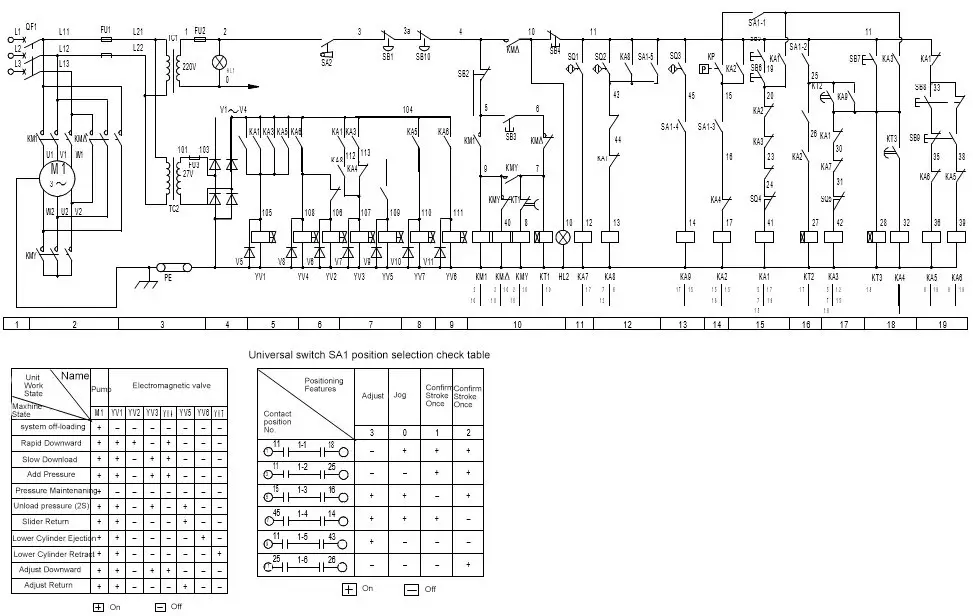
The hydraulic press machine is designed to operate on 380V, 50Hz power, with the control circuit voltage supplied by a 220V transformer.
The press includes a dedicated electric cabinet that can be placed in a convenient location. The cabinet features a door with switches, control buttons, and signal lamps. Inside the cabinet are various controllers, including a power switch, programmable controller, thermal relay, AV contractor, time relay, transformer, intermediate relay, and more.
Depending on the requirements of the pressing technology, the machine can be operated in two ways: manual or semi-automatic. In manual mode, operators adjust the machine and die and perform actions such as slider down, backstroke, ejecting, and piston retreat by pressing the corresponding buttons to start and stop working.
In semi-automatic mode, a single pressing cycle can be initiated by pressing the “work” button.
Technical parameters for driving device and electrics
The hydraulic press machine utilizes two sets of Y180L-6 three-phase squirrel-cage asynchronous motors with a power of 22kW, operating at ~380V and 1470rpm.
The solenoid directional control valve of the hydraulic system is driven by 16 wet-type electromagnets operating at DC 24V.
The main technical parameters displayed on the electrical data tag are as follows: total power of 44kW, voltage of ~380V, three-phase system, frequency of 50Hz, a rated current of the general fuse at 100A, and a protection rate of IP54.
Stroke signaling components
The function of each limit switch is as follows:
SQ1 – Slider backstroke limit switch: This switch is used to detect the end position of the slider during its backstroke movement.
SQ2 – Signal switch of slider backstroke: This switch is used to send a signal to the control system when the slider reaches a specific position during its backstroke movement.
SQ3 – Limit switch of the limiter: This switch is used to detect the end position of the limiter during its movement.
SQ4 – Upper limit switch on the hydraulic pad: This switch is used to detect the upper position of the hydraulic pad.
SQ5 – Lower limit switch on the hydraulic pad: This switch is used to detect the lower position of the hydraulic pad.
Electric operation method
Brief Introduction to Current Technology Procedures:
First, initiate the motor, ensuring that the motor’s rotating direction is consistent with the pump direction. If not, the system may not work or even break down.
Initial Position: Use the inching action to move the slider to the extreme position. Then, the SQ1 limit switch begins to work, ejecting the piston to the low position and triggering the SQ5 limit switch.
Operation Procedures:
Other actions
Emergency Stop: In case of an emergency where the machine needs to stop all work immediately, press the SB1 button. The machine will stop working at once.
Emergency Stroke: In case of an emergency where the slider needs to return stroke at once, press the SB1 button. The machine will stop working immediately and the slider will return stroke.
Cut Off Power: When using the machine, the first step is to turn the rotary switch to the “turn on power” position. When finished with work, turn the rotary switch to the “turn off power” position.
Electric interlocking and electric protection device
6.1 The master circuit must incorporate an automatic switch for short circuit protection. The motor should be equipped with a thermal overheat relay for overload protection. The control circuit must use a small-sized high breaking circuit breaker in case of circuit short.
6.2 The hydraulic press should be equipped with a photoelectric protection program, and users can prepare a photoelectric protector with the following interface specifications: 220V power, wire No. “0, 12” for power, and wire No. “60, 84” for hold-open signal.
6.3 All electrical equipment must be equipped with special grounding devices for safety purposes.
Electric components list of the hydraulic press:
| Code | Name | Model/Specification | Quantity | Remarks |
|---|---|---|---|---|
| M1.2 | Motor | Y180L-6 | 2 | 22kW |
| M3 | Motor | Y132S-4 | 1 | 5.5kW |
| QF1 | Small high-breaking circuit breaker | DZ47-63 | 1 | 3P30A |
| QF2 | Small high-breaking circuit breaker | DZ47-63 | 1 | 2P3A |
| QF3 | Small high-breaking circuit breaker | DZ47-63 | 1 | 1P3A |
| QF4,5 | Small high-breaking circuit breaker | DZ47-63 | 2 | 1P1A |
| QF6,7 | Small high-breaking circuit breaker | DZ47-63 | 2 | 1P6A |
| KA1-19 | Intermediate relay | RE-407AL | 19 | 24V |
| DC | ||||
| SQ1-10 | Limit switch | GB0524NA | 10 | |
| SA1 | Knob | LAY7-11Y/2 | 1 | |
| SA2,3 | Knob | LAY7-20X/2 | 2 | |
| SB3,5 | Button | LAY7-11D/2 | 2 | HL2,3 |
| Belt lamp | ||||
| SB2,4 | Button | LAY7-11BN/1 | 2 | |
| SB6,7 | Mushroom-head button | LAY7-11/M | 2 | |
| SB20 | Mushroom-head button | LAY7-11/M | 1 | |
| KM1-6 | AC Contactor | 3TF46/220V | 6 | |
| KM7 | AC contractor | 3TB43/220V | 1 | |
| PLC | Programmable controller | FXON-60MR | 1 | |
| KT1,2 | Time relay | JSS20/~220V | 2 | |
| KT3,4 | Time relay | JSZ0/~220V | 2 | |
| QS | Air switch | DZ20-100/34 | 1 | |
| TC | Control transformer | JBK3-400 | 1 | |
| VC | DC power | 1 | ||
| YA1-19 | Electromagnet | 17 | Follow with hydraulic | |
| HL1 | Signal lamp | LAY7-XD/25 | 1 | ~6V White |
| HL4,5 | Signal lamp | LAY7-XD/21 | 2 | ~6Vd Red |
When unloading the hydraulic press machine at the destination, first carefully wipe away the antirust oil. When hanging the machine, pay attention to selecting the gravity center and place a protection pad on the contact position to avoid using a thin sheet for loading, which could damage the meters and components.
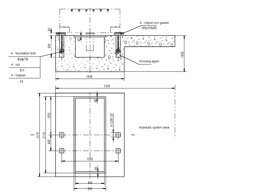
The hydraulic press should be installed on a concrete foundation designed according to the attached drawing. The user should design other waterproof measures and safety lighting devices based on actual conditions.
The installation steps for the hydraulic press are as follows:
| No. | Faults | Reasons | solutions |
|---|---|---|---|
| 1 | Action failure | 1. Electric connecting wire become loose or connecting wrong | 1. Inspect the electric |
| 2. Control oil tank pressure is insufficient | 2. Properly increase the oil pressure up to 1.5MPa | ||
| 3.Oil volume too little | 3. Add more oil | ||
| 2 | Slider crawl | 1. Some air accumulated in the system or pump suck air | 1. Inspect whether some air come into the oil pipe, then move times and increase pressure |
| 2. Improper accuracy adjustment or vertical column lacks oil | 2. Add some oil into the vertical column, readjusting the accuracy | ||
| 3 | Slider holds some pressure when slowly run down | Bearing pressure too large | Adjusting back valve to fully release pressure in the upper chamber, Max. pressure shall less than 1 MPa |
| 4 | Slider slips heavily when stopping the machine | 1. Sealing ring on the cylinder mouth leakage | 1. Inspec the cylinder brim, if leaks, replace it |
| 2. Pressure is too small or leakage | 2. Adjust the pressure and check the cylinder brim | ||
| 5 | Pressure gauge pointer swing heavily | 1. There is some air in the oil pipe of the pressure gauge | 1. Slightly loose the connector to release air when increase pressure |
| 2. Pipeline mechanical vibration | 2. Firmly fasten the pipeline | ||
| 3. The pressure gauge has been broke down | 3. Exchange the pressure gauge | ||
| 6 | High-pressure stroke speed is not enough, increase pressure slow | 1. The flow of high-pressure is too small | 1. Adjust according to the pump instruction, and eccentric can adjust to 5 steps when 25MPa |
| 2. Pump wears or burns | 2. If oil back mouth is heavily damaged, dismount for inspect | ||
| 3. System inter leakage heavily | 3. First, inspect whether the infusing valve has been closed, then inspect other components respectively | ||
| 7 | Pressure relief is too quick under the pressure-holding condition | 1. Valve mouth concerned pressure holding is not fully sealed or pipeline leakage | 1. Inspect the infusing valve, and pressure holding& relief condition |
| 2. The sealing rings are damaged | 2. Replace new sealing rings |
The faults mentioned above are only common faults and are for reference purposes only. When encountering actual faults during daily use, it is necessary to analyze the possible causes and then address the problems one by one.
Proper use of the hydraulic press machine and adherence to maintenance and safety operation rules are essential for prolonging the machine’s service life and ensuring safe production.
It is therefore important to be familiar with the machine’s structural performance and operating procedures. Additionally, we offer some tips for maintenance and safe operation based on general conditions for user reference.
Maintenance of hydraulic press
We recommend adopting N46 hydraulic oil. If using machine oil or turbine oil, the selection should be based on the temperature. When the room temperature is less than 20°C, 20# machine oil or 22# turbine oil are acceptable. When the room temperature is higher than 30°C, 30# or 40# machine oil is acceptable. The oil temperature should be controlled within 15°C~60°C.
Oil must be strictly filtered before being infused into the oil tank.
The working oil should be replaced every year, and the first replacement interval time should not exceed three months.
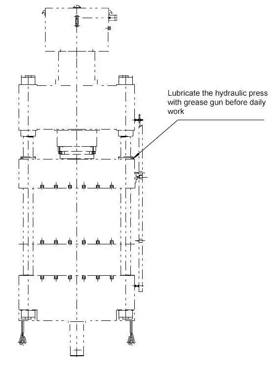
Regularly infuse lubricating oil on the slider. The exposed surfaces of the column and piston should be kept clean and infused with machine oil each time before working.
The acceptable eccentricity is 75mm under a concentrated load nominal pressure of 500t.
Inspect and calibrate the pressure gauge every six months.
If the hydraulic press has been idle for a long time, all machined surfaces should be cleaned and coated with anti-rust oil.
Safety operation rules of hydraulic press
Operators who are not familiar with the structural properties or operating procedures of the hydraulic press cannot start the machine without permission.
All overhaul and die-adjustment work should not be done while the machine is working.
If there is any severe leakage or abnormal situation, such as unreliable action, excessive noise, or vibration, etc., the machine should be stopped, and the reasons should be analyzed. Machines with faults cannot be put into use.
Exceeding the maximum eccentricity distance and maximum load is prohibited.
Exceeding the maximum stroke is prohibited, and the closed height of the die should not be less than 500mm.
The electric grounding device must be reliable and secure.
Vulnerable components of the master motor, master cylinder and top cylinder.
| Part Name | Drawing No.& Code | Component Name | Material | Quantity | Remarks |
|---|---|---|---|---|---|
| Master Motor | Guide Sleeve | HT200 | 8 | Attached drawings | |
| Master cylinder | TDM-YA320 | Sealing ring | PU | 3 | |
| TDM-YA295 | Sealing ring | PU | 1 | ||
| D320x5.7 | “O” shaped ring | Oil resistant rubber | 2 | GB1235-76 | |
| D220x5.7 | “O” shaped ring | Oil resistant rubber | 2 | GB1235-76 | |
| Piston head | HT200 | 1 | Attached drawings | ||
| Cylinder brim guide sleeve | HT200 | 1 | Attached drawings | ||
| Cylinder | D140x3.1 | “O” shaped ring | Oil resistant rubber | 2×4 | GB1235-76 |
| D70x3.1 | “O” shaped ring | Oil resistant rubber | 2×4 | GB1235-76 | |
| TDM-YA100 | Sealing ring | PU | 2×4 | ||
| TDM-YA140 | Sealing ring | PU | 3×4 | ||
| Cylinder guide sleeve | HT200 | 1×4 | Attached drawing | ||
| Piston head | HT200 | 1×4 | Attached drawing |
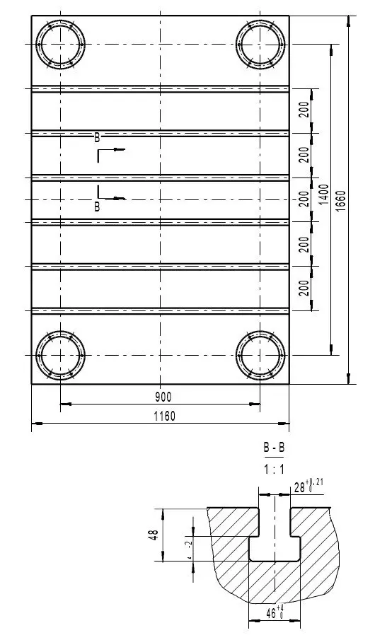
Fig 1. Hydraulic Press Worktable Top View
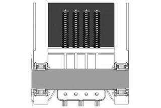
Fig 2. Hydraulic Press Ram Upward View
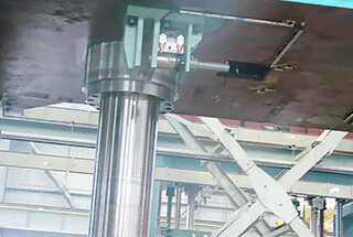
Fig 3. Hydraulic Press Master Cylinder
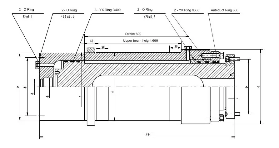
Fig 4. Hydraulic Press Master Cylinder Mounting Diagram
Fig 5. Hydraulic Press Ejection Cylinder Assembly Drawing
Fig 6. Hydraulic Press Hydraulic Principle Diagram
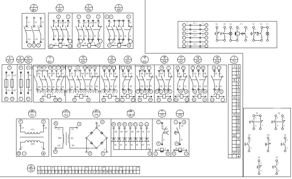
Fig 7. Hydraulic Press Electrical Drawings
Fig 8. Hydraulic Press Wiring Diagram of Electrical Box
Fig 9. Hydraulic Press Lubrication Diagram
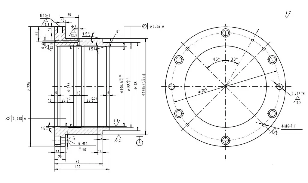
Fig 10. Hydraulic Press Guide Bushing
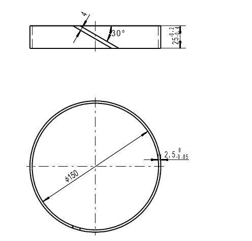
Fig 11. Hydraulic Press Guide Ring

As the founder of MachineMFG, I have dedicated over a decade of my career to the metalworking industry. My extensive experience has allowed me to become an expert in the fields of sheet metal fabrication, machining, mechanical engineering, and machine tools for metals. I am constantly thinking, reading, and writing about these subjects, constantly striving to stay at the forefront of my field. Let my knowledge and expertise be an asset to your business.
