Press Brake Operation Manual (Training PDF)
Attention all mechanics and engineering enthusiasts! Have you ever wondered about the ins and outs of operating a press brake machine? In this blog post, we'll dive into the world…
Have you ever wondered what makes press brake dies so fascinating? In this captivating blog post, we’ll delve into the intricate world of these essential tools that shape the metal fabrication industry. Join us as we explore the various types, materials, and heat treatment processes that give press brake dies their remarkable properties. Whether you’re a seasoned professional or a curious enthusiast, this article will provide valuable insights and deepen your appreciation for these engineering marvels.

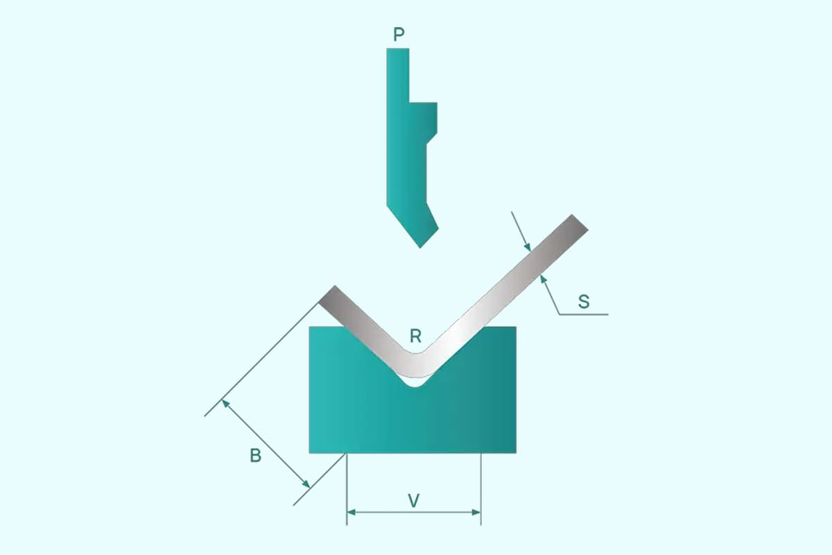
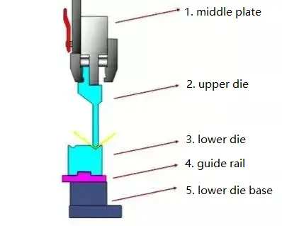
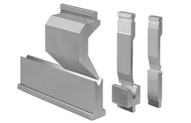
The press brake die is a tool utilized by the press brake machine to form sheet metal. This tool comprises of various components, and the composition of the tooling can vary.
The primary function of the press brake die is to alter the physical state of the material being formed, thus shaping the part.
Press brake dies can typically be divided into several parts, including the upper die, lower die, guide rail, and lower die base. These dies offer a great deal of versatility, with many of them able to be manufactured.
PS: regarding how to make press brake dies, we will cover this topic later.
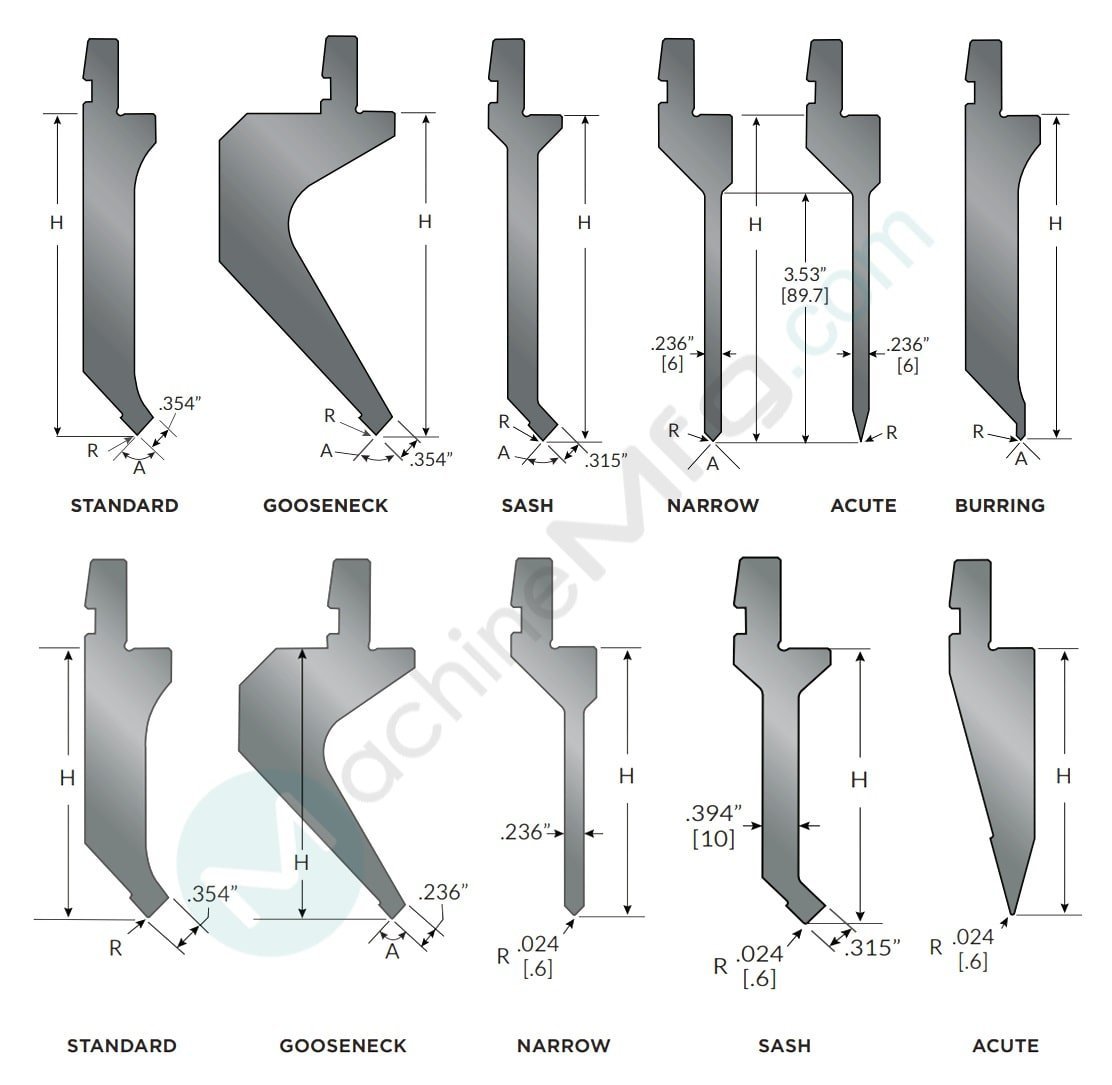
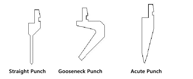
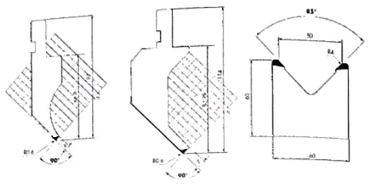
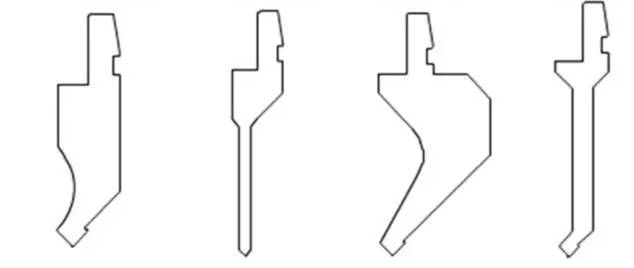
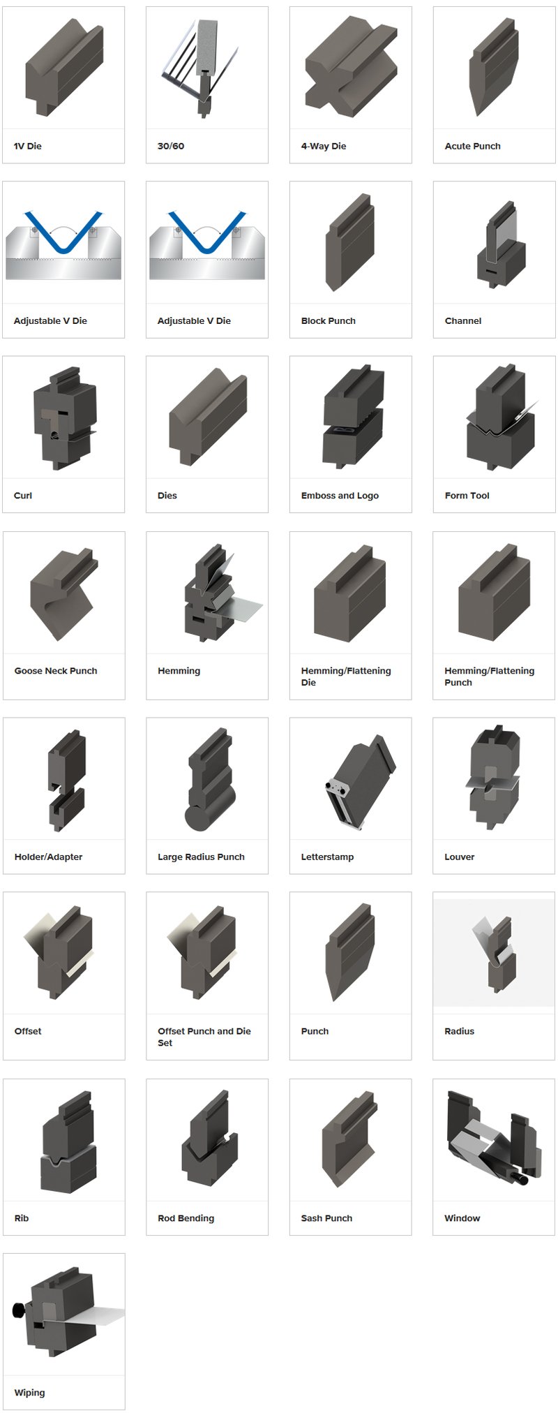
To extend the life of the mold, the press brake punch and dies are designed with rounded corners whenever feasible. The commonly used press brake dies include:
Typically, the height of the flanged edge should be at least three times the thickness of the plate (t), or L ≥ 3t. If the height of the flanged edge is too low, it becomes difficult to form even when using a bending die.
Further reading:
| Punch Type | Main Application |
| Straight Punch | Fabricated angles ≥90° |
| Goose Neck Punch | Fabricated angles ≥90° |
| Acute Punch | Fabricated angles ≥30° |
Further reading:
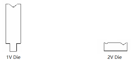
| Punch Type | Main Application |
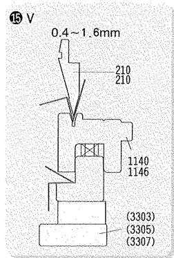
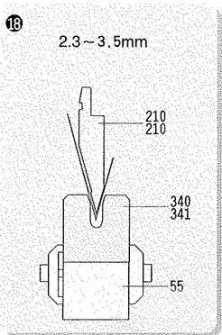
| Sing V Die | 1. While V angle = 88°(ref), able to bend angles ≥ 90° |
| Double V Die | 2. While V angle = 30°(ref), able to bend angles ≥ 30° |
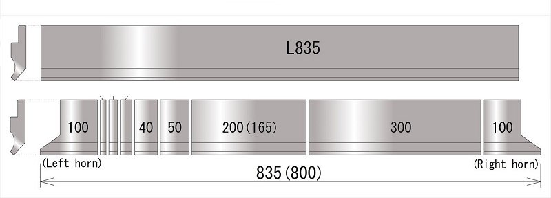
Typically, the standard length of a press brake punch and die set is 835mm, and it can be divided into various sizes to accommodate the bending of workpieces of different lengths.
The sizes usually include 10mm, 15mm, 20mm, 40mm, 50mm, 100mm, 200mm, and 300mm, totaling up to 835mm.
What are press brake dies made of?
There are various materials that can be utilized to manufacture press brake tools, including steel, alloy materials, and polymer materials, among others.
Currently, steel is the most widely used material for producing press brake tools, including T8 steel, T10 steel, 42CrMo, and Cr12MoV.
42CrMo is a high-strength alloy steel that has undergone quenching and tempering to display high strength and toughness.
It can operate at low temperatures down to -500°C and is known for its high strength, toughness, and resistance to wear.
The common materials used for press brake dies can be divided into eight categories.
1. Carbon tool steel
T8A and T10A carbon tool steels are frequently used in the manufacture of press brake dies because of their good machinability and cost-effectiveness.
However, these materials have poor hardenability and red hardness and can undergo significant deformation during heat treatment. Additionally, they have a low capacity to bear loads.
2. Low alloy tool steel
By incorporating the appropriate amount of alloy elements into carbon tool steel, low alloy tool steel is produced, which reduces the deformation and cracking tendency during quenching and improves the hardenability and wear resistance of the steel.
Some of the commonly used low alloy steels in the production of press brake dies include CrWMn, 9Mn2V, 7CrSiMnMoV, and 6CrNiSiMnMoV.
3. High carbon and high chromium tool steel
High carbon and high chromium tool steel is known for its good hardenability, toughness, and resistance to wear.
It undergoes minimal deformation during heat treatment, making it a high-wear-resistant steel with a load-bearing capacity second only to high-speed steel.
However, due to significant carbide segregation, repeated upsetting and drawing (axial upsetting and radial drawing) are required to reduce the heterogeneous nature of the carbides and improve its performance.
Some of the common high carbon and high chromium tool steels include Cr12, Cr12MoV, and Cr12MoV1.
4. High carbon medium chromium tool steel
High carbon medium chromium tool steels utilized for press brake dies include Cr4W2MoV, Cr6W, Cr5MoV, among others.
These materials have low chromium content, fewer eutectic carbides, uniform carbide distribution, minimal deformation during heat treatment, good hardenability, and stable dimensions.
Compared to high carbon and high chromium steel which can exhibit significant carbide segregation, these materials offer improved properties.
5. High-speed steel
High-speed steel is frequently used in the production of press brake dies due to its high hardness, resistance to wear, and compressive strength. It also has a high load-bearing capacity.
W18Cr4V, W6Mo5, and Cr4V2 with reduced tungsten, as well as 6W6Mo5 and Cr4v high-speed steels developed to enhance toughness, are commonly used.
In order to improve its carbide distribution, high-speed steel also requires forging.
6. Basic steel
Basic steel is produced by adding a small amount of other elements to high-speed steel and adjusting the carbon content to enhance its properties.
This results in improved properties compared to high-speed steel, such as increased wear resistance and hardness, as well as better fatigue strength and toughness.
It is a press brake die steel with high strength and toughness, and it is more cost-effective than high-speed steel.
The commonly used basic steel materials in press brake dies include 6Cr4W3Mo2VNb, 7Cr7Mo2V2Si, 5Cr4Mo3SiMnVAL, among others.
7. Cemented carbide and steel bonded cemented carbide
The hardness and resistance to wear of cemented carbide in press brake die steel are the highest, but its strength and toughness when bending are poor.
Tungsten cobalt is used as the cemented carbide in press brake dies.
For press brake dies that require low impact and high resistance to wear, cemented carbide with low cobalt content can be selected. For high-impact dies, cemented carbide with high cobalt content can be used.
Steel-bonded cemented carbide is made through powder metallurgy, using iron powder and a small amount of alloy element powder (such as chromium, molybdenum, tungsten, or vanadium) as the binder and titanium carbide or tungsten carbide as the hard phase.
The matrix of steel-bonded cemented carbide is steel, which addresses the poor toughness and difficult processing of cemented carbide.
This material can be cut, welded, forged, and heat treated. Steel-bonded cemented carbide contains many carbides and has a hardness and resistance to wear that is lower than that of cemented carbide but still higher than other steel grades.
After quenching and tempering, its hardness can reach 68-73 HRC.
The material utilized for the press brake tool is a type of cold working die steel, and its primary performance requirements are strength, toughness, and resistance to wear.
Currently, the development trend in press brake die steel has two main directions, both centered around high alloy steel D2 (Cr12MoV).
(1) Improving the toughness of press brake die involves reducing the carbon content and alloy element content and enhancing the uniformity of carbide distribution in steel. Examples of this direction include 8CrMo2V2Si and Cr8Mo2SiV.
(2) Improving the resistance to wear of press brake die to accommodate high-speed, automated, and high-volume production with powder high-speed steel. An example of this direction is 320CrVMo13.
In order to improve their mechanical features, tools are subjected to heat treatments such as quenching and hardening.
QUENCHING:
This is a heat treatment consist-ing of heating and sub-sequently cooling steel to reduce the material’s intermal stress. During the heating process martensite is produced, which has a very hard structure and high ultimate tensile strength but low resilience.
As a result, the material can be easily broken; to avoid this problem, the steel is then tempered by controlled cooling. The cooling speed during tempering has a major effect on the residual stress of the steel, as the slower the cooling phase, the weaker the residual stress.
Steel types which can undergo this treatment contain 0.4-0.6% carbon and are therefore referred to as quenched and tempered steel.
HARDENING:
The purpose of this treatment is to increase the hardness of the material and it consists of heating the steel to a certain temperature and then rapidly cooling it.
The usual method used to measure the hardness of the tools is the Rockwell hardness test which is carried out with the conical (HRC) or spherical (HRB) indenters.
It involves gradually increasing the load on the instrument. The hardness is determined by the depth of penetration of the indenter into the piece.
INDUCTION HARDENING:
This is the most common heat treatment for press brake tools, but as it is a surface treatment, it affects only the external layer of a tool.
This type of hardening uses the the principle of electromagnetic induction: by placing a conductive material (a coil)into a strong alternating magnetic field, the tool is heated to a high tempereture and then rapidly cooled by a flow of coolant.
Induction hardening creates very hard surfaces, resistant to wear and fatigue without affecting the toughness of the core.
CORE HARDENING:
Some press brake tool manufacturers use core hardening to obtain consistent hardness throughout the whole tool, with lower values for the surface, which usually suffers wear.
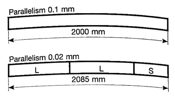
In the past, press brake tools were produced in a single piece that was as long as the press brake or the profile to be bent. These steel tools were planed, since hardening and grinding would have deformed them due to their length. Since the tools could not be machined, their precision was quite low, about 0.1 mm per meter.
With the advent of new technologies press brake tool precision has improved significantly. Today tools are produced, hardened and machined pieces, which can guarantee greater precision (0.0mm per tol) and have better mechanical properties than before. Press brake tool length varies according to the type, e.g. Promecam tools are 835mm long.
It is essential that the tools are of the correct size, and are perfectly interchangeable and aligned to take advantage of modern press brakes and to guarantee high quality bends and repeatability.
Thanks to the surface finishes produced by grinding machines, modern press brake tools can be produced with a radius in the die vee and in the punch tip.
This makes it possible to bend uniformly without marking the sheet metal, and to know the exact point of contact between tools and the sheet metal. This is essential information for the press CNC system for automatically seting the bending parameters to achieve maximum repeatability.
Different dies should be used to fabricate different workpieces. To select the appropriate press brake die, it’s important to have a thorough understanding of both the press brake machine and the die’s fabrication parameters.
The parameters of the press brake machine include the stroke, operating capacity, daylight (open height), and middle plate type.
The parameters of the die include the type of upper die shank (to match the middle plate) and the maximum bending force.
Dimensions
The characteristics of the profile to be bent and of the press brake itself strongly influence tool shape. For this reason different shapes are available forcarrying out different jobs.
Shape
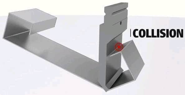
It is important to evaluate the overall dimensions of the sheet metal during bending to avoid collision and to make working on the press brake easier. For example, gooseneck punches are available for bending U-channels and pillar dies for making tight counterbends.
In order to choose the most suitable tools, it is a good idea to simulate each of the bending phases around the tool on apiece of graph paper.
Another important aspect is that the tool shape influences the tool’s capacity, for example, a gooseneck punch can handle fewer tonnes than a straight punch made of the same tool steel.
Stroke (mm) = Daylight – Middle Plate Height – Upper Die Height – Lower Die Height – (Lower Die Height – 0.5V + t)
t = plate thickness(mm)
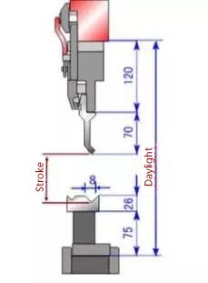
Given: daylight 370mm, max stroke 100mm
Reach: stroke = 370-120-70-75-(26-0.5*8+t) = (83-t)mm
Note: 0.5V < stroke < max stroke
It’s important to note that lower die bases come in different heights, which are utilized for various fabrication purposes. So, don’t overlook this when selecting a lower die base.
Further reading:
Different combinations of tools and dies can produce various combined heights for various fabrication purposes of parts.
Upper die shank type
Upper die shank has three types to match different middle plate.
Upper die shape
Common standard upper die:
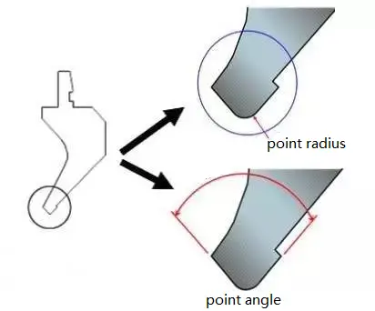
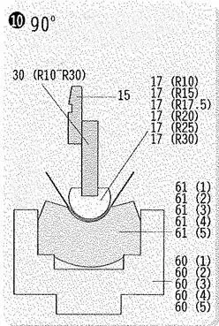
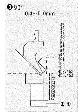
Upper die tip radius & top angle
The punch tip radius must always be less than the internal radius to be produced on the profile. Should too small a radius be used, a mark will be clearly visible on the inside of the profile.
Die radius is the meeting point between the upper surface of the die and the oblique surface of the die vee. The greater the radius, the less is friction between the die and the sheet metal during bending.

Common punch tip radius includes:
(1)0.2R (2)0.6R (3)0.8R (4)1.5R (5)3.0R
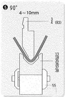
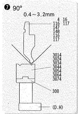
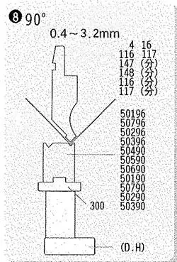
When choosing the appropriate press brake die tip radius, a tip radius of 0.6R is recommended for plate thicknesses less than 3mm. The standard upper die tip angles include 90°, 88°, 86°, 60°, 45°, 30°, etc.
The dihedral angle of the die should be less than the fabrication angle. For instance, if the workpiece’s bending angle is 90°, a die with a tip angle of 88° should be selected.
Angle:
Standard tools have angles from 26° to 90° and the choice of angle depends on the profile to be produced. Therefore, an operator must select and mount tools with a narrower angle than the angle to be produced less springback.
For example, if an operator has to bend stainless steel at 90° with a 5° springback, he should mount tools with an angle of 85° or less. As we will see in the following chapters, the choice of the tool influences the profile and in the case of the dies, it also influences the maximum die capacity (the smaller the angle, the lower the capacity).
Further reading:
Lower die type
Typically, there are two types of lower dies: single V type and double V type.
The single V type die has a broader range of applications compared to the double V type die, and the separated die is more commonly used than the full-length die. The choice of the lower die depends on the specific fabrication purpose.
Lower die V width (die opening), V groove angle
Die vee (V) opening is very important for:
The die width is useful for checking the die size and possible collision with the sheet metal. In the case of counterbends, the minimum counter bend achievable is half the die width.
V groove choosing & plate thickness (T):
| T | 0.5-2.6 | 3-8 | 9-10 | ≥12 |
| V | 6×T | 8×T | 10×T | 12×T |
| Plate Thickness | ≤0.6 | 1.0 | 1.2 | 1.5 | 2.0 | 2.5 | 3.0 |
| Die Width | 4 | 6 | 8 | 10 | 12 | 16 | 18 |
In order to choose a small V die for bending purposes in special cases, the spread of each punch should be increased by 0.2mm.
Further reading:
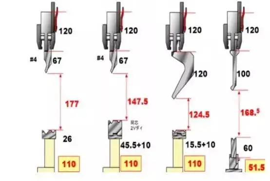
Working height
The working height of a tool must be calculated accurately to avoid collisions during bending operations. Punch working height can be calculated as follows:
Total height — tang height;
whereas die useful height is the same as the total tool height.
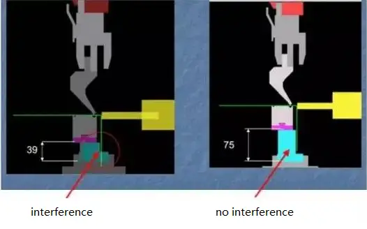
When choosing tools, it is important to check that the press brake stroke is long enough and that the daylight is greater than the sum of punch height + die height + sheet metal thickness.

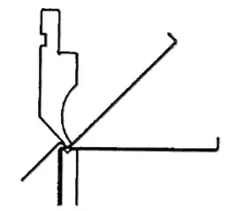
Normally min bending size:
— L-type: slot width/2 + plate thickness
— Z-type: slot width/2 + plate thickness * 2
Reference Value:
| Plate Thickness | ≤0.6 | 1.0 | 1.2 | 1.5 | 2.0 | 2.5 | 3.0 |
| L-type | 4.0 | 4.5 | 5.0 | 6.0 | 8.0 | 10.5 | 12.0 |
| Z-type | 5.0 | 5.5 | 6.0 | 8.0 | 10.0 | 13.0 | 15.0 |
The manufacturer of press brake dies is responsible for producing punches and dies for press brakes.
To purchase press brake dies, the easiest method is to request a quote from the press brake manufacturer.
Typically, the press brake manufacturer has a partnership with the press brake die manufacturer, meaning that the manufacturer of press brake dies will be a supplier for the press brake machine factory.
Further reading:
The cost of press brake dies typically depends on various factors, such as market conditions, customer psychology, competition, and the status of the manufacturer.
The press brake die manufacturer will perform a comprehensive analysis of these factors to determine the cost of their punches and dies.
They may start with a base price that is increased by 10-30% to account for valuation, but this quote can be negotiated and reduced based on the specific situation. The final price is agreed upon by both parties and outlined in the contract.
It should be noted that the mold price may be higher or lower than the initial valuation, which only estimates the basic cost of production and does not consider additional costs or profits.
It’s important to note that the initial quotation for the press brake dies is not the final price and only serves as an estimate for development costs.
After the product has been successfully developed and generates profits, the added value of the mold fee will be extracted as compensation, forming the final mold price.
This price may be higher than the original estimate and have a high rate of return, ranging from dozens to hundreds of times the normal mold price. However, it’s also possible for the rate of return to be zero.
It’s important for the manufacturer to prioritize quality, accuracy, and service life of the press brake dies over cost. Pursuing low prices should not compromise the quality of the highly technical product.
It’s worth noting that mold valuations and prices can vary between enterprises, regions, and countries due to factors such as equipment technology, personnel concepts, and consumption levels.
In more developed areas or larger, technologically advanced enterprises, the focus may be on high quality and high prices, while in areas with lower consumption levels or smaller enterprises, the estimated mold prices may be lower.
It’s also worth mentioning that mold prices can change over time, and the immediate effect of mold price can be poor.
Different time requirements and manufacturing cycles result in different mold prices, with different prices for a pair of molds at different times and different prices for molds with different manufacturing cycles.
Further reading:
Click below link to download the press brake toolings catalog:
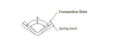
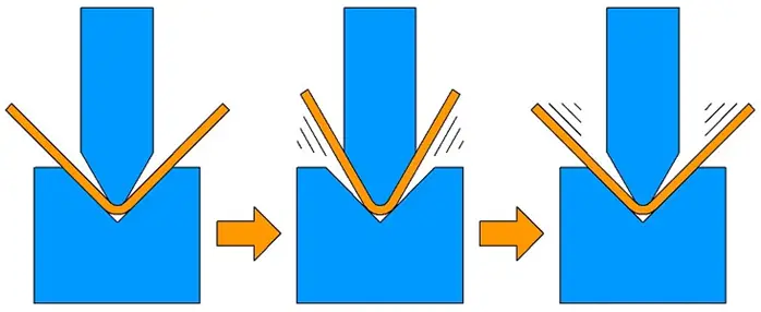
Spring-back angle Δα=b-a
In the formula:
b—The actual angle of the workpiece after spring-back
a—Die angle
Spring-back Angle for single 90 o free bending
| Steel | r/t | Plate Thickness t (mm) | ||
| <0.8 | 0.8-2 | >2 | ||
| Mild Steel | <1 | 4° | 2° | 0° |
| Brass | 1-5 | 5° | 3° | 1° |
| Aluminum, Zinc | >5 | 6° | 4° | 2° |
| Medium carbon steel σb=400-500MPa | <1 | 5° | 2° | 0° |
| Hard brass σb=350-400MPa | 1-5 | 6° | 3° | 1° |
| Hard bronze σb=350-400MPa | >5 | 8° | 5° | 3° |
| High carbon steel σb>550MPa | <1 | 7° | 4° | 2° |
| 1-5 | 9° | 5° | 3° | |
| >5 | 12° | 7° | 6° | |
The factors that affect the resilience and the measures to reduce the spring back:
The angle of spring-back is proportional to the yield point of the material and inversely proportional to its elastic modulus (E).
To reduce spring-back for sheet metal that requires high precision, low carbon steel should be considered first, rather than high carbon steel or stainless steel.
The larger the relative bending radius (r/t), the smaller the degree of deformation and the larger the rebound angle (Δα). This is a critical concept.
When material properties permit, the small bend radius should be chosen to increase accuracy.
Care should be taken to minimize the design of large arcs, as they have a greater negative impact on production and quality control.

Further reading:
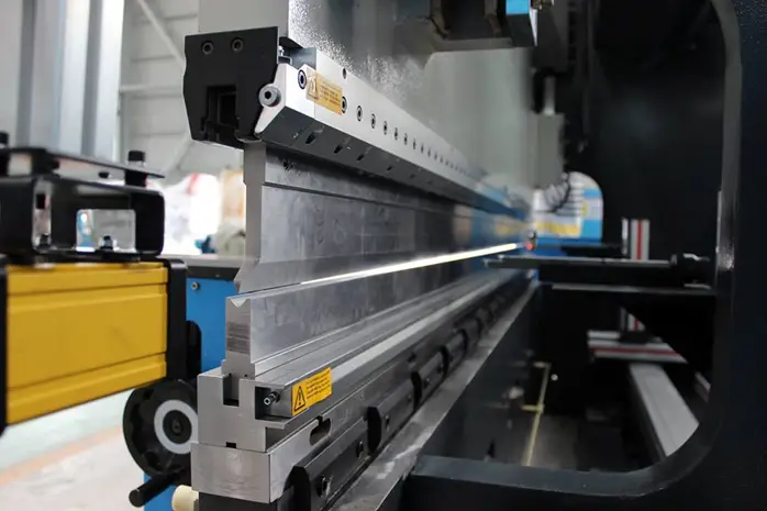
A press brake is a forging machine commonly utilized in the metal processing industry. The tooling for the press brake consists of several components.
It is imperative to carefully examine the equipment prior to installation and to strictly adhere to the instructions.
Additionally, prioritize safety during both the installation and commissioning process.
Well, what are the precautions during the installation and commissioning of press brake tooling?
Press brake adjustment
Before installation, it is important to carefully adjust the performance of the machine with patience and attention to detail.
It is also crucial to inspect the machine for any dust or iron debris and to perform thorough cleaning to prevent any future problems.
Ram stroke adjustment
Before installation, be sure to inspect the thickness of the die and verify that the proportion of the upper and lower die is correct.
Typically, the die should be aligned at the point of transition for the stroke line.
Stroke module adjustment
This is to correctly set the upper limit of the stroke.
Once the machine module reaches its highest level, activate the switch and secure the position of the ram.
It is also advisable to slow down the descent of the module to better protect the machine and its dies.
Gap adjustment
The main goal is to accurately measure the distance between the upper and lower modules.
The precise gap should be determined based on the material that will be folded.
Angle adjustment
The angle adjustment is closely tied to the product being manufactured. Typically, for 90° bending dies, the central angle should be greater than the angle between the two sides.
Tightness can be adjusted using the screw.
It is important to ensure proper pressure by adjusting it according to the pressure gauge to prevent damage to the die.
For those who may be curious about how to set press brake dies, the method largely depends on the press brake controller being used.
Typically, only CNC controllers, such as the Delem DA52s or DA66T controller, have the capability to set the dies for a press brake.
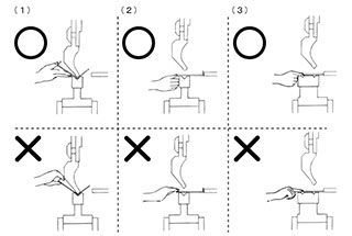
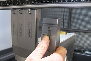
The alignment of the tools is essential for avoiding problems during bending.
The operator should mount the tools, tighten the clamp screws slightly, lower the upper beam until the punch tip reaches the vee bottom, keep the upper beam in this position and then fully tighten the clamp screws.
If the tools are not aligned, the operator should change their position. If the problem follows the tools wherever they are positioned, measure them and if necessary replace them; if the problem remains in the same position, check the intermediates.

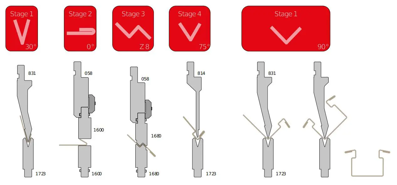
Depending on the bending type selected, the operator can choose tools with different angles.
In this instance, he must pay great attention, as incorrectly matching punch and die may cause tool breakage or deformation.
The rule to follow is that the operator must always use punches with the same or a smaller angle than the die vees.
To avoid changing tools, operators sometimes use punches with a wider angle than the dies. This solution may deform or damage the die; furthermore, the sheet metal can be badly marked by the high pressure applied at the point of contact between punch and die.
This solution can only be used if extreme care is taken during the press brake stroke setup and only when air bending angles greater than 90°.
Tool breakage or deformation are common problems when tools are used with too much bending force.
Breaks are easily identified but deformation sometimes cannot be seen with the naked eye but nevertheless affects bending quality. For example, a reduction in the height of the tool will result in a wider angle inthe bend.
Many CNC systems calculate the tool capacity automatically and stop the press brake in the event that the force is exceeded, but others do not, so operators have to calculate the maximum force to be used.
It should also be remembered that operators can bypass CNC systems by entering incorrect parameters for the tools mounted, e.g. by increasing the length of the sheet metal. In this case, there is a risk of the tools being severely damaged.
In other cases, the CNC system may calculate a load of just a few tonnes whereas in fact the figure is much higher, since the weight of the upper beam applies a force as well.
For this reason, press brake operators must know the maximum bending force of each tool in order not to reduce their life, typically 1 million bends, and must be aware that the length of the tools actually in contact with the sheet metal is the key factor in calculating the maximum force.
In order to clarify this concept, consider the following example:
As you can see, the total length of the tool mounted on the press brake is not important, but only the part of it that is actually working!
A simple rule might be helpful: a tool with a maximum capacity of 600KN/m can bear a maximum of 6KN/cm.
As already mentioned, operators must always take into consideration that a press brake, unless it is very modern, tends to use the weight of its upper part(about 10% of its maximum force) as part of the force applied.
This factor determines the press brake minimum force, which is very important to calculate to avoid risks when bending short profiles.
To keep press brake, tools, intermediates or adapters in good condition, operators must never use more than the maximum permitted force per meter.
Where Promecam intermediates are mounted on the press brake, the operator must observe the 1000 KN per metre maximum limit and, as 5 intermediates are mounted per meter, the maximum is 200 KN each.
For this reason, we recommend avoiding the use of more than 200 KN with short punch segments mounted on one single intermediate; if necessary, use longer punches mounted on more than one intermediate.
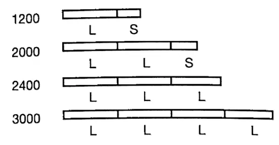
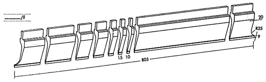
In order to compose specific tool lengths for specific profiles, tools are available in a variety of sizes. For example, a long tool can be divided into smaller segments with sections as small as 10mm in length; the length and quantity of the segments depend on the tool type and the manufacturer.
Usually when a punch is sectioned, two horn pieces, one left and one right, are also produced. They are tools which have a tip that is longer than the tang and they are useful for bending pieces with dimensions that would otherwise cause collisions with the upper part of the punch.
Sectioned tools have the same features as the long tools they derive from, with the exception of the horn pieces,which have a lower capacity.
Sectioned tools are used when a specific length is required as in the case of boxes, or items which have edges bent upwards or downwards and that would, therefore, collide with the tools that were not of the correct length.
To mount sectioned tools properly, the shortest segments should be mounted near the clamp screw to keep them seated and prevent them from sliding downwards.
This problem is caused by a deformation in the clamps and it can be avoided by inserting a shim between the punch tang and the clamp.
Furthermore, the shortest segments should be mounted between longer tools to prevent them from shifting during bending and creating empty spaces between them, which could affect the profile’s dimensions and appearance.
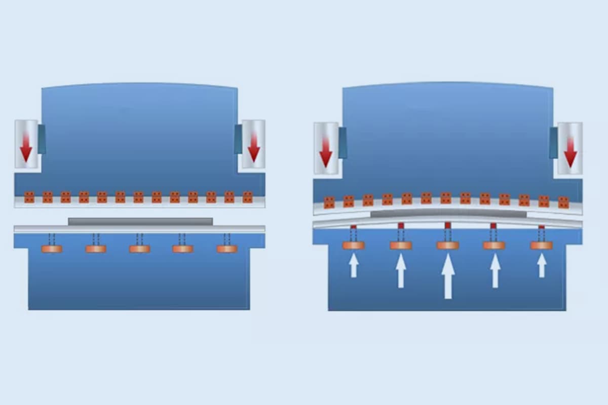
Hydraulic crowning systems mounted on the lower beam may affect the alignment of highly sectioned dies, especially in the vee area. To avoid this problem, operators should use shorter dies or reduce cylinder push and consequently pressbrake deformation.
The production standards for press brake tooling depend on maintaining accuracy and precision in angle. If these factors are not taken into account, it can lead to subpar production results.

(A) Factors that affect the accuracy
(B) Factors that affect the accuracy of the angle
How to use press brake toolings?
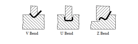
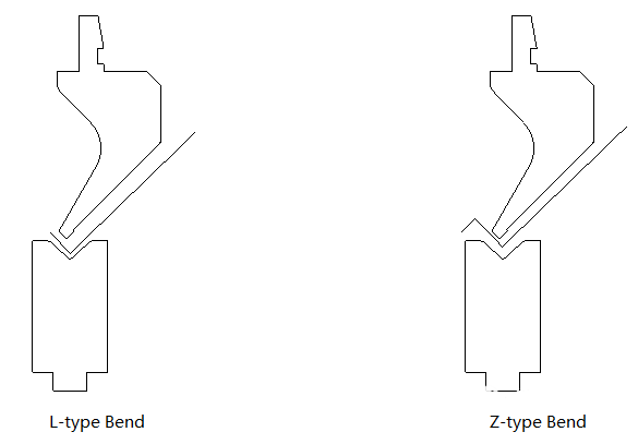
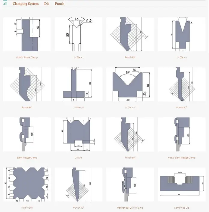
Press brake tooling encompasses a variety of shapes including L-shape, R-shape, U-shape, and Z-shape bends. The upper die of the press brake is comprised of various punch angles including 90°, 88°, 45°, 30°, 20°, and 15°.
The lower die, on the other hand, includes options such as dual-V die and single-V die with varying slot widths ranging from 4V to 18V.
Additionally, there are specialized lower dies such as R-lower die, acute angle lower die, and hemming/flattening die.
Further reading:
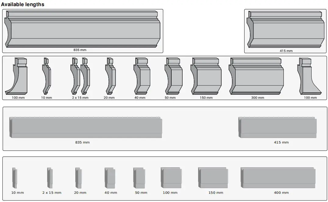
Both punch and die are available in both separate and full-length options. The separated upper die options come in lengths of 300mm, 200mm, 100mm, 100mm, 50mm, 40mm, 20mm, 15mm, and 10mm, with a combined length of 835mm.
Similarly, the separated lower die options come in lengths of 400mm, 200mm, 100mm, 50mm, 40mm, 20mm, 15mm, and 10mm, with a total length of 835mm.
① The press brake bending molds are made from high-quality steel that has undergone special heat treatment, making them hard, durable, and capable of withstanding high pressure.
However, each mold has a limit on the amount of pressure it can bear, expressed in ton/meter. It is important to choose the appropriate length of the mold based on the maximum amount of pressure it can handle.
② To prevent damage to the die, it is crucial to align it with the original point using the 300mm upper and lower molds.
The upper and lower molds must have the same height and cannot be aligned using smaller split molds. The alignment must also be based on the regulated pressure within the press brake machine.
③ The molds can only be used in a press brake machine with the same height and cannot be used in machines with varying heights.
④ When operating the press brake tooling, it is important to choose the appropriate upper die and lower die based on the hardness, thickness, and length of the sheet metal.
The slot width of the lower die should be 5-6 times the thickness of the metal plate and should be longer than the sheet metal.
The harder and thicker the sheet metal, the wider the slot of the lower die should be.
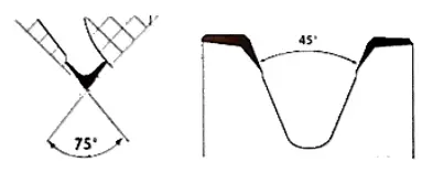
⑤ When bending at an acute angle or a dead angle, a 30° punch should be used. The acute angle should be bent first, followed by flattening.
When bending an R angle, an R punch and R die should be selected.

⑥ When bending long pieces, it is best to avoid using segmented molds to prevent indentations at the connection points.
Instead, it is recommended to use a single-slot die, as the exterior angle “R” of a single-slot “V” lower die is larger and therefore less likely to cause bending indentations.
⑦ When selecting the top punch, it is important to consider the type of die and its parameters, and then determine the appropriate punch based on the desired product shape.
⑧ It is not recommended to use press brake dies for bending hard or excessively thick materials such as steel bars or cylindrical products.
⑨ Press brake mold operators must be attentive and focused while working.
After aligning the upper and lower dies of the press brake machine, it is important to securely lock them to prevent the punch from falling and causing injury or damage to the die.
Care should be taken to apply pressure gradually during the operation, without exceeding the recommended pressure limits, and monitoring the display screen for any changes in data.
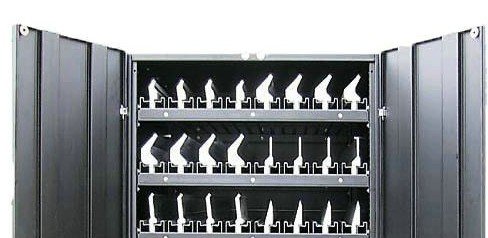
⑩ Upon completion of the press brake tooling operation, the dies should be returned to the press brake die cabinet or storage area, labeled and organized properly.
Regular cleaning of the dies to remove dust is necessary, and applying anti-rust oil can help prevent rust and maintain the precision of the tooling.
U-bending should always use a gooseneck die, of which we currently have three sizes: small, medium, and large.
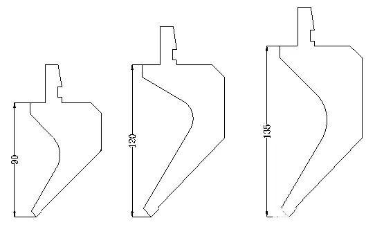
U bending size range

Note: A size do not include plate thickness
Further reading:
The cabinet will be convenient for you to store the press brake punches and dies.


Further reading:
High precision press brake tooling is a crucial component in the sheet metal processing system.
However, there are significant variations in the life and precision of bending dies among manufacturers, due to differences in equipment, materials, and technology used during the production process.
To provide guidance for sheet metal users when selecting bending molds, this analysis provides a brief explanation of relevant aspects of bending die production.
The sheet metal processing industry is a crucial component of the machinery manufacturing industry, and bending is a common and essential process in sheet metal fabrication.
To improve the quality and production efficiency of parts, it is important to choose a high-quality bending die.
So, what is the key to achieving good quality bending dies in the production process?
The Status of Press Brake Toolings
Currently, sheet metal users face several challenges when it comes to press brake tooling:
(1) There is a significant discrepancy compared to bending dies made in Europe, with an uneven distribution of mold brands, unstable mold quality, and poor precision.
(2) The cost of using imported bending dies is high and the lead time for delivery is lengthy.
(3) Communication channels with mold manufacturers for non-standard molds are limited, and response times are slow.
(4) The lack of a standardized mold industry means that manufacturers cannot interchangeably use each other’s molds, leaving sheet metal users with limited options for purchasing bending equipment only from press brake manufacturers.
Materials
For press brake bending dies, the ideal material to use is 42CrMo from reputable steel companies.
This material possesses exceptional mechanical properties, including high strength and hardenability, excellent toughness, minimal deformation during quenching, and high creep strength and persistent strength at high temperatures.
While T7A and T8A materials are also available in the market, they have a soft tool core and are more prone to deformation due to the shallow depth of the quenching layer.
However, some manufacturers may choose cheaper materials due to cost constraints.
Heat treatment
The heat treatment process is critical in obtaining qualified and uniform hardness for the bending die.
The desired hardness for the bending die should be 47±2HRC, meaning that the hardness at any position of the mold should be within the range of 45-49HRC and the depth of the hardness layer should be over 10mm.
The heat treatment process can be described as follows:
First, the hoisting ring is welded on the end face of the blank mold after rough milling, and then it is placed in a heating furnace until it reaches a temperature of 880℃.
The mold is then discharged, quenched in oil, cooled, checked for deformation, corrected through cold correction, tempered, and tested for hardness.
The tempering time will vary depending on the batch of molds. After these steps, the rough milling blank mold will have undergone its heat treatment process.
The above steps have several key points to consider:
Due to the irregular geometry of the bending die, cooling occurs at varying speeds, leading to significant deformation and lack of control.
To effectively minimize mold deformation, only suspended combustion and suspended cooling methods should be used.
In the heating and cooling process, the hoisting ring is first welded to the bending die before it is placed in the heating furnace.
However, if the mold is too heavy, the hoisting ring and mold may fracture at a temperature of 880°C.
To ensure that the mold can withstand heat treatment, the bending die factory requires that press brake bending dies be produced with a standard length of 835mm.
If defects occur during the heat treatment process, the lifespan of the mold will be greatly reduced.
After the mold is removed from the oil furnace, its irregular shape can cause uncontrollable amounts of deformation.
To address this issue, each mold must be checked for deformation, and if the deformation is too significant, it must undergo cold correction.
Some manufacturers use outdated methods, such as flame gun burning, to correct deformation, which can lead to local softening and pose safety hazards during use.
To ensure a long service life for the bending die, strict control over the heat treatment process is necessary.
If a stainless steel plate with a thickness of 2.0mm (including 2.0mm) or a cold plate under 3.0mm (including 3.0mm) is bent using a lower die with a V opening of 6-8 times the thickness, the R angle of the bending edge can withstand 2 million bends (calculated based on 200,000 bends per year for 10 years) with an abrasion of the cutting edge of less than 0.03mm.
While lower prices may seem more cost-effective, it is important to consider the number of uses.
Only professional heat treatment techniques and high-quality materials can ensure the durability of the bending die. In the long run, the lower cost may not be worth it.
Further reading:
Precision CNC forming grinding
The material of the mold and heat treatment discussed in the first two points primarily focus on the longevity of the bending die.
However, the processing method of the cutting edge and V groove are key processes in ensuring the precision of the die.
There are two methods available: traditional grinding and CNC Precision Grinding.
Traditional grinding relies heavily on human intervention throughout the process, while CNC grinding is fully controlled by equipment and the CNC controller.
This difference in consistency and stability is a major factor contributing to the lack of an industry standard for bending dies.
Each manufacturer produces molds to their own specifications, making it difficult for sheet metal users to choose the best die for their needs.
If there were a uniform size standard, users would have more freedom in choosing a manufacturer.
The most common lengths of press brake bending dies are 835mm, 500mm, and 515mm.
While accuracy should always be a priority, a lightweight mold can improve production efficiency and reduce the workload of production personnel.
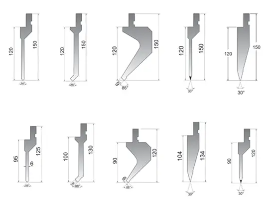
Fig.1 Commonly used top punch.

Fig.2 Different V slot ratios for the lower die
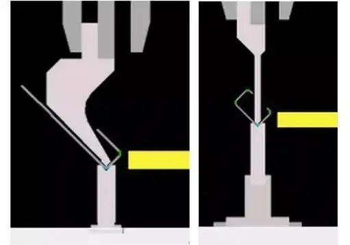
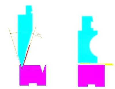
When using an acute punch, it is important to pay attention to the opening angle of both the upper and lower dies.
The angle of the upper die must be less than or equal to the opening angle of the lower die, or it can result in damage to the lower die and pose a potential hazard.
Revised:
The operation specification for using the flattening die to bend the workpiece in the non-flattening state is as follows: The standard flattening die has a length of 835mm x 3 = 2505mm, as shown in Figure 1.

Figure 1
1) When the bending length of the workpiece L<835mm:
Wrong way:
Place the workpiece between the two lower dies, as shown in Figure 2:

Figure 2
The correct approach:
Place the workpiece in the middle of any segmented lower die, as shown in Figure 3:

Figure 3
2) When the bending length of the workpiece 835≤L<1670mm:
Wrong way:
Place the workpiece in the middle or on the far side of the entire die, as shown in Figures 4 and 5.

Figures 4

Figures 5
The correct approach:
Place the workpiece in the middle of any two lower die, as shown in Figure 6:
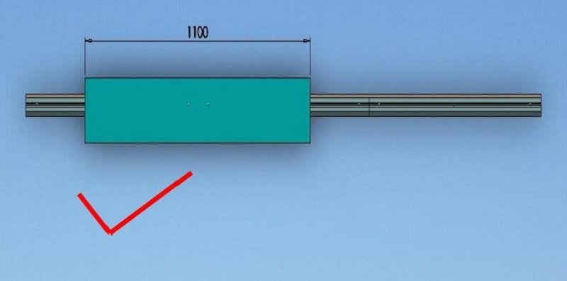
Figure 6
3) When the bending length of the workpiece 1670≤L≤2505mm
Wrong way:
Place the workpiece on the far side of the entire mold, as shown in Figure 7:

Figure 7
The correct approach:
Place the workpiece in the middle of the middle of the mold, as shown in Figure 8:

Figure 8
Note:
To extend the lifespan of the mold, it is important to follow proper operating instructions as outlined above.
Improper use of the flattening die can result in failure of the return spring, breakage of the guide set screw, and even damage to the flattening die itself.
The bending die, as the central component of the press brake machine, has a direct impact on the appearance, accuracy, production cost, efficiency, quality stability, and operator safety of the bending process.
For parts with stable order quantities and large batches in the sample stage, process capability analysis should be conducted in advance.
Complex structures require various die structures and forms, leading to long processing times and disrupting the production rhythm.
To clear obstacles for mass production, early screening of structures and a reasonable matching of molds is necessary.
Small-sized parts that are challenging to control and locate, with processing hazards and low efficiency in large single batches, can be improved by customizing special forming dies in the press brake for process optimization.
Customizing the special forming die in the press brake for process optimization offers several benefits compared to the previous hard die processing by press machines.
The special forming die on the bending machine is more flexible in terms of die switching, debugging, and processing, and has a higher return on investment for the die.
This leads to improved production efficiency, more stable product quality, and effectively avoids the safety risks associated with small-sized parts in the bending process.
The following case studies demonstrate the workshop’s recent improvements in process capability through the customization of special forming dies in press brake machines for efficient production.
Case 1
At the start of the project, normal single-step bending was used, and the final product required three folds, as shown in Figure 1.

Fig. 1 Single step bending before improvement
Due to the small size of the workpiece and the presence of two bending edges, the contact area between the reference plane and the rear positioning is limited, making it challenging to securely position the workpiece.
This leads to low bending efficiency, difficulties in maintaining bending accuracy, and potential safety risks during the processing process. As a result, only 1000 pieces are produced in one run.
To meet the production schedule, it is often necessary to operate multiple press brakes at the same time.
To enhance the process, a customized forming die was created based on the number of repeat orders.
As a result of the improvement, the process now allows for the simultaneous processing of 6 bending edges and 2 products, as shown in Figure 2.
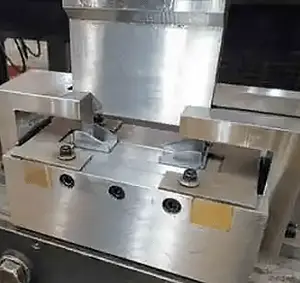
Fig. 2 One step processing of customized special forming die after improvement
The use of the forming die ensures the accuracy of the parts and significantly improves bending efficiency. It eliminates the risks associated with the single-step bending process of the original small parts.
As a result, there is no longer a need to use the original high-precision upward-moving press brake.
Instead, the older downward-moving press brake can be utilized, which helps to distribute the press brakes in the production line and frees up production capacity.
Case 2
As depicted in Fig. 3, the workpiece requires four bends and flipping with strict tolerance requirements.
However, the center distance and flatness of the finished product are not up to standard, leading to a high rate of initial waste for the sample.
There is significant potential for improvement in both production efficiency and product quality.

Fig. 3 Bending before improvement
Due to the high standards for the appearance of the product, using micro-connections after continuous folding is not a viable option.
To meet these requirements, a custom-made forming die was created for single-step forming processing.
As a result, the process can now complete four finished products with a total of 16 bends in one cycle, as shown in Figure 4.
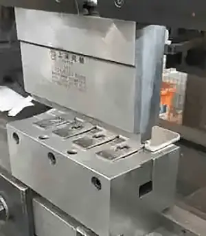
Fig. 4 One-step forming process with customized special forming tool after improvement
The use of the custom-made forming die has resulted in a six-fold increase in efficiency compared to the previous method.
This approach ensures that the workpiece meets the tolerance requirements outlined in the drawing, while also maintaining accuracy and flatness, thus ensuring stability in product quality.
Case 3
The bending surface of the workpiece depicted in Fig. 5 is only 8 mm wide and has a symmetrical design. However, the two beveled bending edges at the root make it susceptible to stretching and deflection.
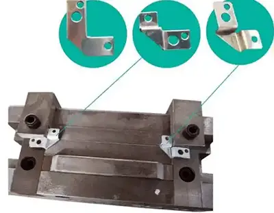
Fig. 5 Customized special forming die for processing
Initially, the small size of the workpiece made it challenging to handle, requiring operators to remove their gloves for positioning.
This resulted in low production efficiency and posed a serious safety risk during the production process.
To address these issues, the project team created a custom-made forming die to improve the process.
The improvement involved the use of right-angle edges for positioning, allowing for the simultaneous production of 2 pieces (8 bends).
This resulted in improved precision and stability of the parts, as well as a significant increase in production efficiency, effectively eliminating any potential safety hazards in the processing process.
Case 4
Box products are highly customizable and come in various sizes. During the bending process, operators need to bend the front and back four times.
To minimize deformation after welding, large structures are often designed as integrated structures, which leads to high labor intensity for employees.
Despite the high degree of customization, the bending structure and size are consistent. To address these challenges, a custom-made forming die was created for processing.
The original 12-step bending process for the box was simplified to 4 steps, with three bends formed in one step.
The use of the forming die eliminates the need to rotate the entire process, as demonstrated in Figure 6, greatly improving bending efficiency.
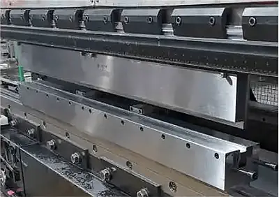
Fig. 6 The whole process does not need to be overturned after improvement
By using a rotary platform for processing, the labor intensity of operators is effectively reduced and the accuracy of welding is ensured.
The implementation of the forming die has certain limitations that must be taken into account in conjunction with the product’s bending structure and sustainable order support.
To optimize production, the concept of rapid die change is applied to common structural workpieces.
This allows for quick die clamping, reducing die replacement and debugging time, maximizing operational time, and minimizing machine downtime, waste from semi-finished product turnover, and other non-value-added activities.
When ordering the mold during the sample stage, engineers should consider this concept to avoid potential challenges such as repeated loading and unloading, mold adjustment, handling, semi-finished product storage, and tolerance issues that can result from accumulated factors during actual production.
To achieve efficient production, the use of concentric equal height molds for simultaneous clamping of multiple structure molds can be considered, as shown in Figure 7.

Fig. 7 Concentric contour die
Given the stable order volume and complex structure of the workpieces, the custom-made special contour die simplifies the original four-step die change process into a single step to complete the final product.
Furthermore, four types of dies, including acute angle, flattening, segment differentiation, and straight punches, are available to produce the final product in one step, as shown in Figure 8.

Fig. 8 Special contour die
Improving bending efficiency is a long-term, comprehensive, and ongoing effort.
By adopting low-cost solutions such as bending forming dies, it is possible to double output while halving input, maximizing the potential of existing equipment.
The integration of high-efficiency die sets and supporting software can significantly enhance the output and efficiency of the bending process.
The following is a brief summary to assist operators and product designers to choose the most suitable press brake tools:
1. Choice of bending type and assessment of tool angle (bending angle – sprin-gback)
2. SSpecification of die width (V = t × 8)
3. Check the minimum internal edge (checking drawings and using the bending ruler with any correction factors)
4. Check the internal radius (checking drawings and using the bending rulerwith any correction factors).
5. Check the required force (KN/m × profile length)
6. Choice of a die (V, α, shape, capacity)
7. Choice of a punch (point angle<die angle, capacity, shape, punch R = internal R × 2/3)
8. Check of press brake force
9. Calculation of sheet metal development with actual radii produced by selected tools
10. Definition of the bending sequence
11. Check for possible collisions (if necessary, choose tools with a different shape)
If you are considering purchasing one or more sets of press brake dies, you can contact us for a FREE quote today.

As the founder of MachineMFG, I have dedicated over a decade of my career to the metalworking industry. My extensive experience has allowed me to become an expert in the fields of sheet metal fabrication, machining, mechanical engineering, and machine tools for metals. I am constantly thinking, reading, and writing about these subjects, constantly striving to stay at the forefront of my field. Let my knowledge and expertise be an asset to your business.