Top 15 Best Stamping Press Manufacturers & Brands in World
Have you ever wondered how the machines that shape our world are made? This blog takes you on a journey through the top punch press machine manufacturers. You'll learn about…
Intrigued by the marvels of metal stamping? In this blog post, we dive into the fascinating world of hole flanging, necking, and bulging. Our expert mechanical engineer will guide you through the intricacies of these processes, explaining key concepts and sharing insider insights. Get ready to expand your knowledge and appreciate the art behind shaping metal like never before!
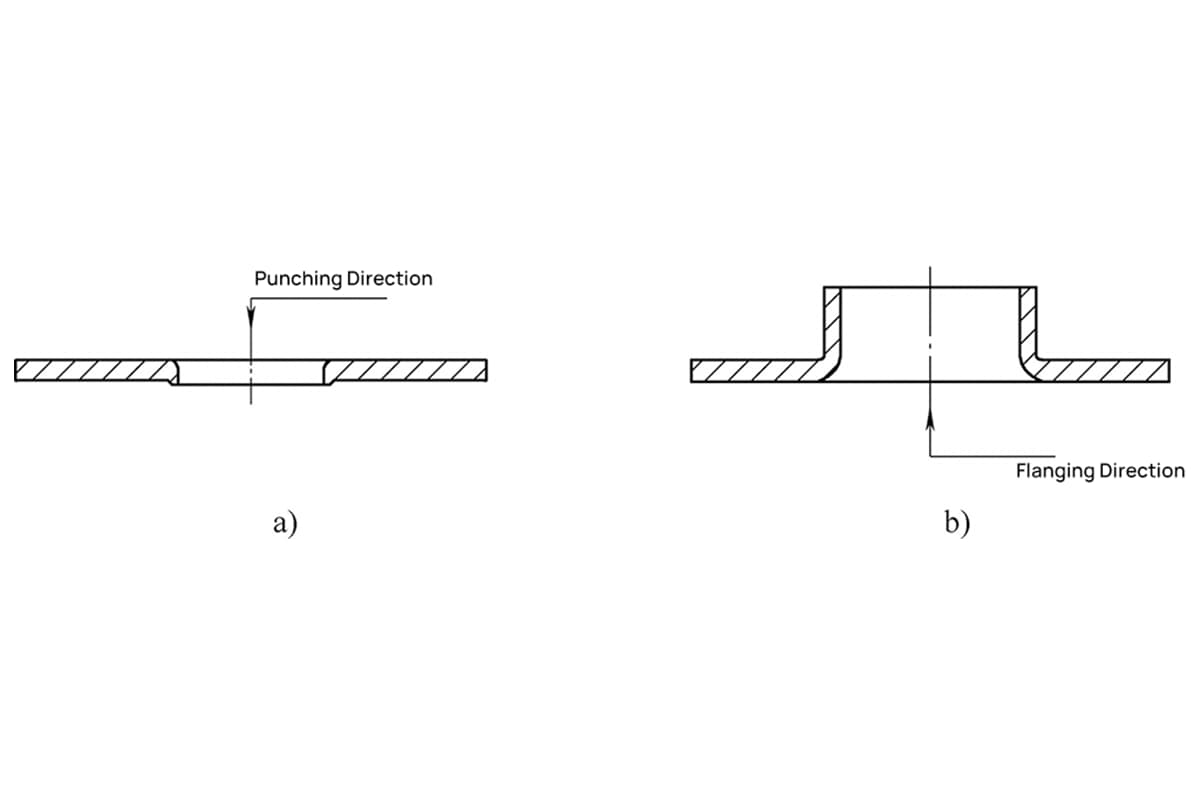
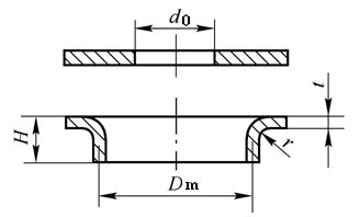
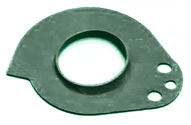
Hole flanging is a punching method that uses a mold to turn the edge of the hole of the part to an upright or a straight edge at a certain angle.
Hole Flanging Type:
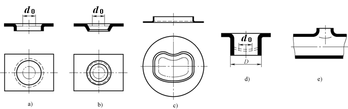
Depending on the shape of the blank and the edge of the hole being flanged, there are flanging holes on the flat plate, and also on the curved surface, such as the flanging hole on the tube blank; the flanged holes can be rounded or non-rounded.
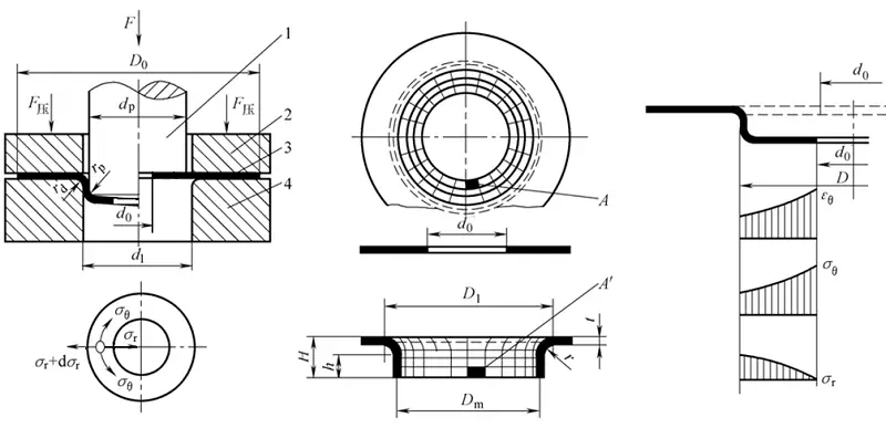
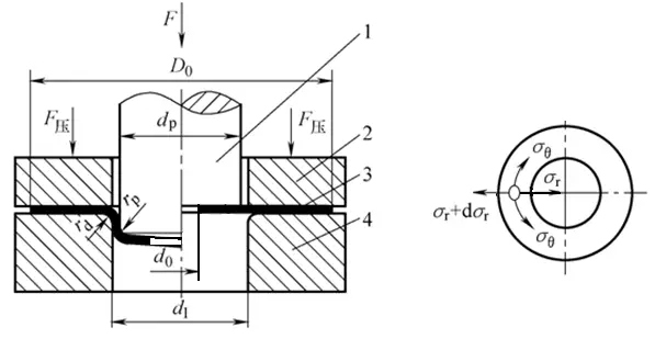
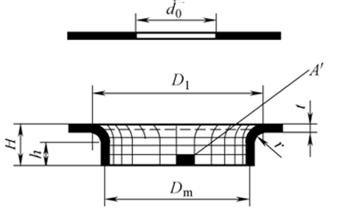
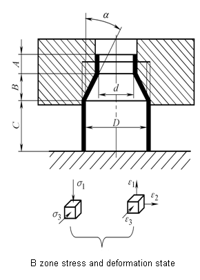
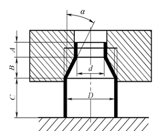
Deformation characteristics of round hole flanging:
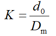
The forming limit is expressed by the hole-flanging factor K:
Limit hole-flanging factor Kmin.
Factors affecting the limit hole flanging coefficient:

(1) Technology of round hole
(2) Process arrangement for round hole
Usually, before flanging the hole, it is necessary to pre-punch the hole for the hole-flanging, and then determine whether it can be turned at one time according to the height of the hole and the coefficient of the hole-flanging, and then determine the forming method of the hole-flanging parts.
(3) Process calculation of plate hole-flanging
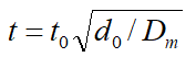
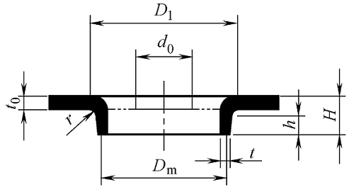
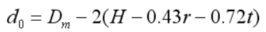
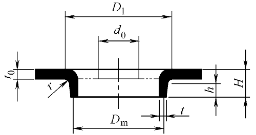
1) Determine the diameter of the pre-punched hole
2) Calculate the height of the hole to determine whether the hole can be successfully turned once.
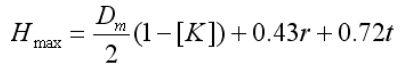
3) Determine the number of turning holes
When the hole-flanging height H <Hmax, it can be flanged at one time.
(4) Process calculation of drawing the bottom hole first and then flanging the hole
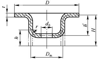
1) Calculate the hole-flanging height h that can be reached after the pre-drawing is:
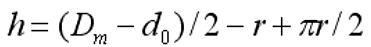
2) Calculate pre-punching diameter and drawing height before hole-flanging:
3) Deep drawing process calculation
(5) Calculation of the hole flanging force
When using a cylindrical flat bottom punch to flange a hole, it can be calculated as follows:
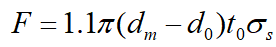
The force for flanging holes with a tapered or spherical punch is slightly less than the value calculated by the above formula.
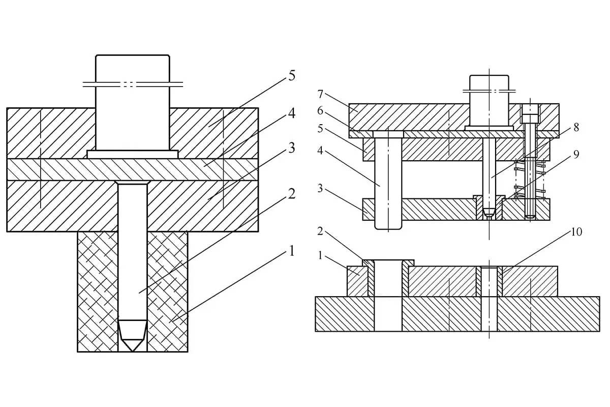
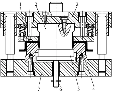
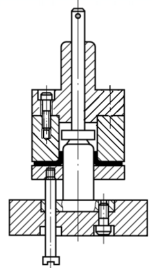
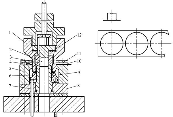
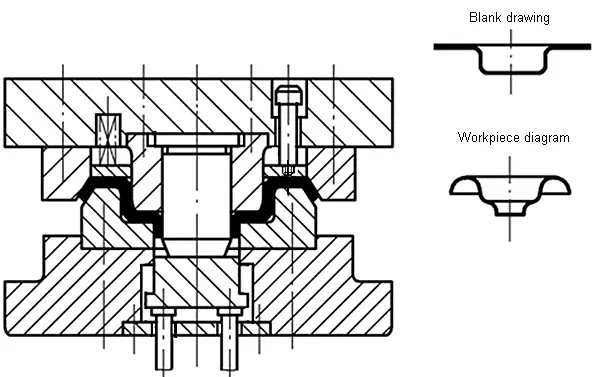
(1) Mold structure of round hole-flanging
Formal hole-flanging die
Inverted hole-flanging mold
Blanking, deep drawing, punching, and hole-flanging compound dies
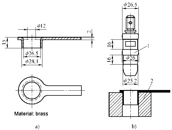
(2) Structure and size design of the working part of the hole-flanging die
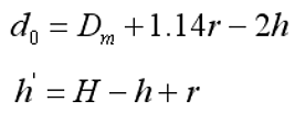
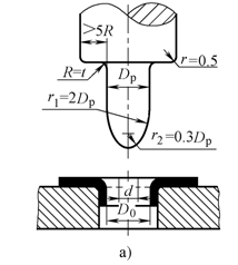
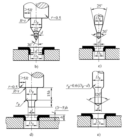
1) Structure and size of round hole punch
2) Clearance C between convex and concave die
Flanging refers to a stamping method that uses a mold to turn the edges of the product into an upright or straight edge at a certain angle.
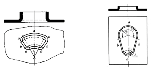
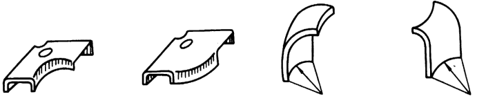
According to the shape of the flanged outer edge:
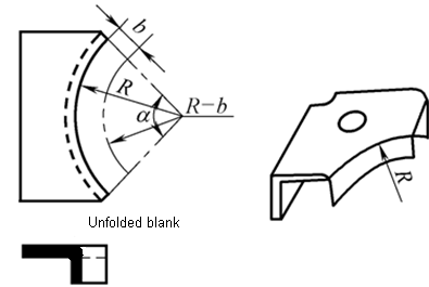
The deformation is similar to a round hole-flanging, which belongs to elongation.
The deformation area is mainly tangentially stretched, and the deformation at the edges is the largest, which is easy to crack.
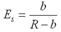
The degree of deformation is:
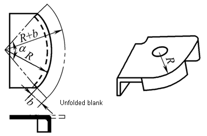
The outer-curved flanging deformation of the outer edge is similar to shallow drawing, and belongs to compression type deformation.
The deformation zone of the billet mainly generates compressive deformation under the action of tangential compressive stress, which is easy to lose stability and wrinkle.
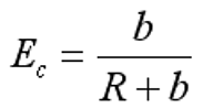
The degree of deformation can be expressed as:
Hole-flanging, Flanging and Shaping
Further reading: Thinning flanging
Thinning hole-flanging or flanging refers to a deformation process that uses a smaller die gap to force the thickness of the vertical edge to become thinner and increase in height.
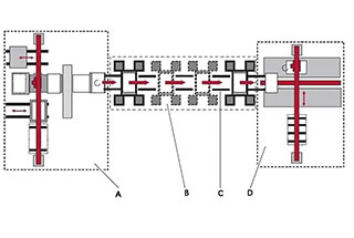
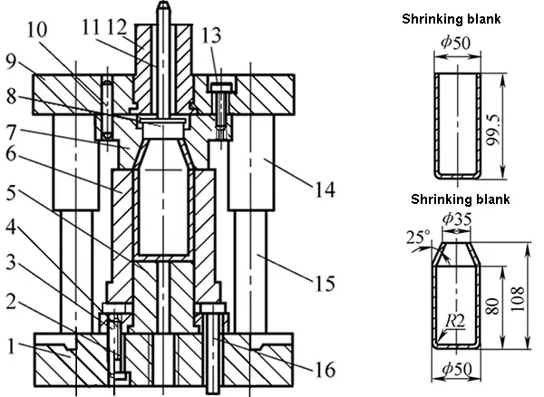
Necking is a stamping method that uses a mold to reduce the radial dimension of the end of a hollow or tubular part.

The degree of necking deformation is expressed by the ratio of the neck diameter after necking to the diameter of the blank before necking.
Shrinking coefficient: m = d / D
The minimum value of the necking coefficient obtained under the premise of ensuring the stability of the necking member is called the limit necking coefficient [m].
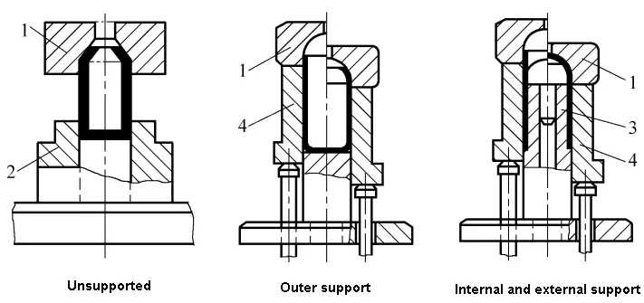
[m] is related to the plasticity of the material and the supporting structure of the mold.
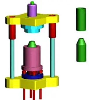
Necking die for different supporting methods
See Table 6-4 for the determination of the size of the blank of the necking piece.
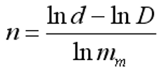
When the actual necking coefficient m is smaller than the limit necking coefficient [m], the necking cannot be performed at one time.
The number of necking can be calculated by:
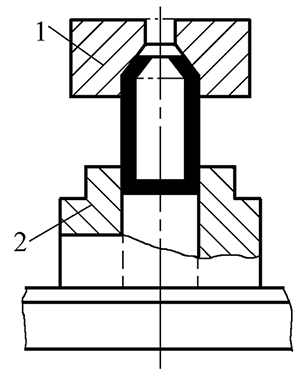
When there is no support necking, the necking force is:
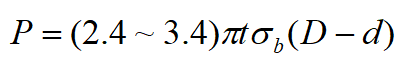
Necking die without support
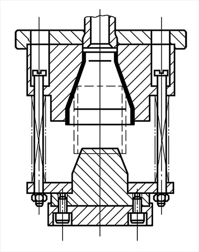
Necking die with external support
Necking and flaring compound dies
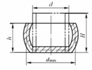
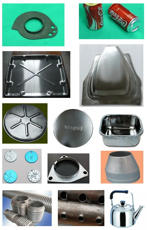
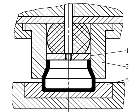
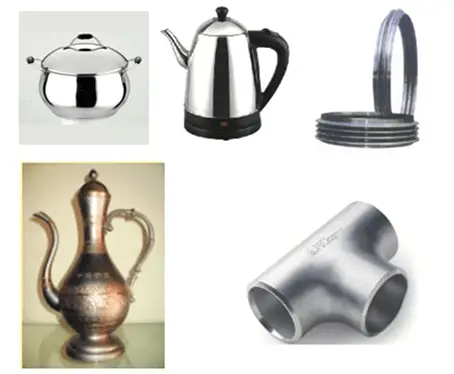
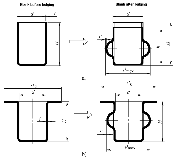
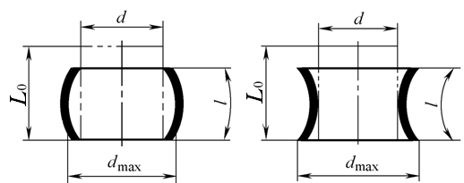
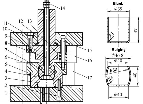
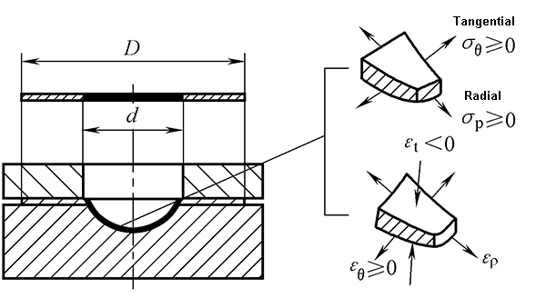
Bulging is a stamping method that uses a mold to plastically deform the interior of a hollow part under the action of two-way tensile stress to obtain a convex part.
The deformation area is almost the entire blank or the open end, and the open end of the blank is contracted and deformed.
Therefore, the deformation in the deformation area is a deformation state in which the circumference is elongated, axially compressed, and the thickness is reduced.
The deformation zone is limited to the part to be swollen in the middle of the blank.
The deformation zone mainly produces elongation deformation in the circumferential direction and thinning in the thickness direction.
Bulging is an elongation-forming process.
Preventing bursting is the key problem to be solved in the bulging process.
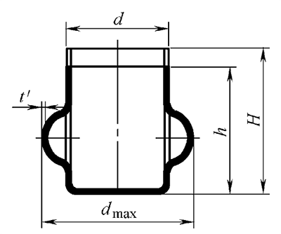
The degree of bulging deformation is expressed by the ratio of the maximum diameter of the convex bulging obtained after bulging and the diameter of the blank before bulging, that is, the bulging coefficient:
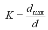
The larger the bulging coefficient value, the greater the degree of bulging deformation.
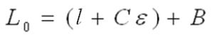
When bulging, the length of the blank when axially allowed to deform freely:
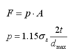
σZ – The true stress in the bulging deformation area, take σZ=σb in approximate estimation.
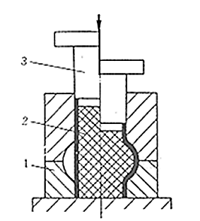
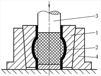
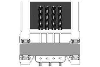
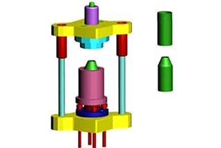
Rubber bulging mold
High-pressure liquid punch bulging
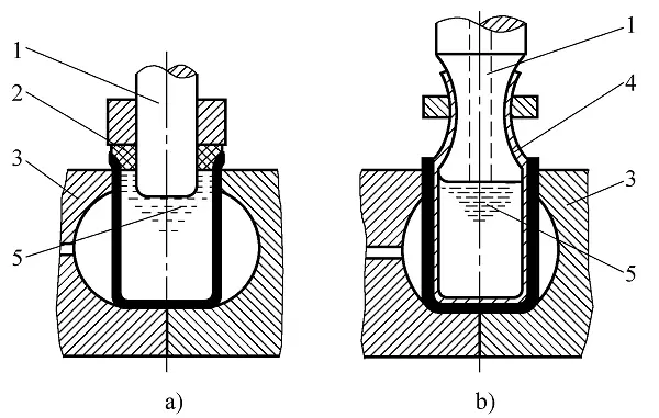
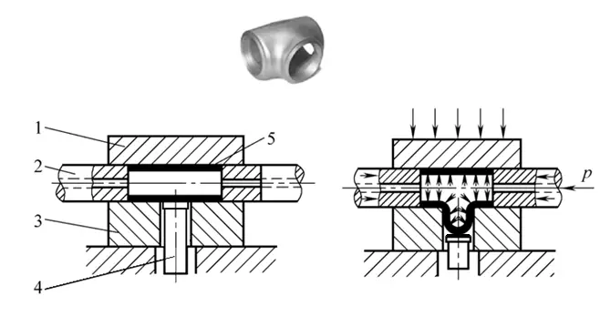
Hydraulic bulging of tee joint
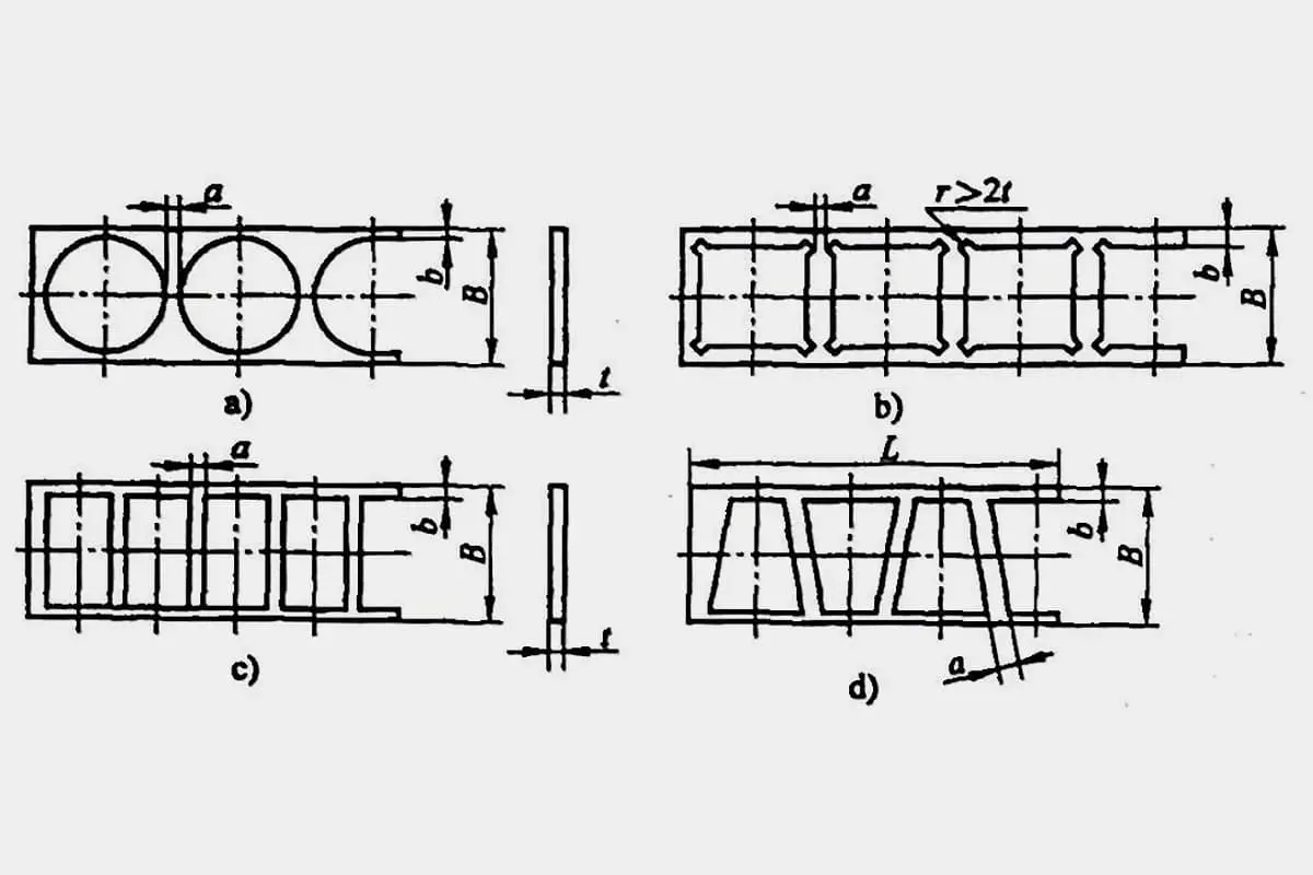
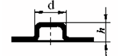
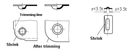
Beading and convex hull pressing are embossing methods that use a mold to produce convex hulls or ribs (reinforcing ribs) on the part.
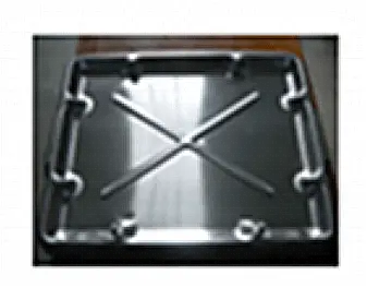
Features of beading and convex hulls forming
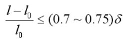
The forming limit of the beading can be expressed by the amount of change in the length of the deformation zone before and after the beading

The forming limit of the convex hull can be expressed by the height h of the convex hull

As the founder of MachineMFG, I have dedicated over a decade of my career to the metalworking industry. My extensive experience has allowed me to become an expert in the fields of sheet metal fabrication, machining, mechanical engineering, and machine tools for metals. I am constantly thinking, reading, and writing about these subjects, constantly striving to stay at the forefront of my field. Let my knowledge and expertise be an asset to your business.