Top 15 Best Stamping Press Manufacturers & Brands in World
Have you ever wondered how the machines that shape our world are made? This blog takes you on a journey through the top punch press machine manufacturers. You'll learn about…
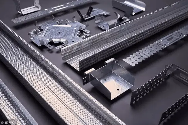
Ever wondered how everyday objects are shaped with precision? This article explores the fascinating world of joint construction stamping technology. You’ll learn about the process, from obtaining technical drawings to designing efficient molds. Get ready to uncover the secrets behind the seamless production of high-quality stamped parts!
Conduct an analysis of the joint construction stamping technology based on relevant data and carry out a process and standardization audit on the workpiece.
(1) Acquire drawings of product parts with specific technical specifications.
Gain an understanding of the workpiece’s shape, size, and accuracy requirements. Determine the critical hole size and location, as well as the critical surface, and perform an analysis to identify the workpiece’s datum.
It’s important to note that the requirements for stamping parts are not set in stone.
With the rapid advancements in stamping technology, it’s essential to use a comprehensive approach and apply various stamping technologies as needed in production. This can be achieved through the rational selection of stamping methods, the proper formulation of the stamping process, and the selection of an appropriate mold structure. This approach will not only meet the technical specifications of the product but also fulfill the requirements of the stamping process.

(2) Gather process cards for the processing of the workpiece.
By doing so, it becomes possible to examine the interconnection between the front and back processes, understand the process requirements and the assembly relationships that must be guaranteed between processes, etc.
(3) Determine the production batch of the workpiece.
The production of the parts has a significant impact on the efficiency of the stamping process. To achieve this, it’s necessary to identify the mold type, structure, material, and other relevant details based on the production batch of parts and the quality specifications of the parts. Analyze the economics of the tooling process and the feasibility of producing public buildings, and outline the stamping step profile.
(4) Specify the conditions and specifications of the raw materials used for the workpiece (such as sheet, strip, coil, scrap, etc.), understand the nature and thickness of the material, determine whether to minimize waste by using less material for sampling, according to the manufacturability of the parts, and initially identify the material specifications and accuracy grade.
When possible, cost-effective materials should be used, provided that they meet the requirements of functionality and stamping performance.
(5) Analyze and design the fiber direction and burr direction requirements in the process.
(6) Evaluate the technical capabilities and equipment conditions of mold making in the mold workshop and the availability of standard mold parts.
(7) Familiarize yourself with the equipment information or status of the stamping workshop.
(8) After thoroughly studying and understanding the above information, formulate an initial design for the mold’s structure.
If necessary, make modifications to the established product design and process to better integrate the product design, process, mold design, and manufacturing, resulting in more optimal outcomes.
Determining the process solution is a crucial step following the process analysis of stamped parts.
It involves:
(1) Conducting a process analysis based on the shape characteristics, dimensional accuracy, and surface quality requirements of the workpiece to determine its key properties and the nature of the basic processes, such as material removal, punching, bending, deep drawing, flanging, and expansion.
The list of individual processes required for stamping can typically be derived directly from the product part drawing specifications.
(2) Establishing the number of processes based on process calculations.
For stretched parts, calculate the number of deep draws. The number of times a bent or cut part should be processed will depend on its shape, size, and accuracy requirements.

(3) Based on the deformation characteristics, dimensional accuracy, and ease of operation of each process, determine the order of the processes.
For example, decide whether to punch first and then bend or bend first and then punch.
(4) Based on factors such as the production batch, size, precision requirements, mold manufacturing level, equipment capacity, and others, determine the optimal combination of single processes that have been arranged.
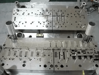
For instance, a compound stamping process or a continuous stamping process. Generally, thick, low-precision, small-volume, large-sized punches are suitable for single-process production using simple dies.
Thin materials, small size, and large numbers of punching parts are ideal for continuous production using a step-in die.
For stamping parts with high positional accuracy, it’s advisable to use composite dies for stamping.
After determining the nature, sequence, and combination of processes, finalize the stamping process and the structure of the dies for each process.
(1) Design the materials and determine the rough dimensions.
(2) Calculate the punching pressure, including the force required for punching and cutting, bending, deep drawing, turning, expansion, discharge, pushing, and crimping. If necessary, also calculate the punching work and power.
(3) Determine the mold’s pressure center.
(4) Calculate or estimate the thickness of each major part of the mold, such as the concave die, die retaining plate, pad, and the free height of the discharge rubber or spring.

(5) Specify the clearance of the convex and concave molds and calculate the dimensions of the working parts of the convex and concave molds.
(6) For the deep drawing process, determine the method of deep drawing (trimming or no trimming), calculate the number of deep drawing operations and the size of the semi-finished product in intermediate processes.
Special calculations may be required for certain processes, such as continuous deep drawing of the strip.
Using the above analysis and calculations, conduct a preliminary design of the mold structure (at this stage, it’s usually sufficient to produce a rough sketch) and estimate the closing height of the mold. Outline the general dimensions of the mold.
(1) Workpiece parts, including the design of the convex mold, concave mold, convex-concave mold, and the selection of a fixed form.
(2) Positioning parts. There are several types of positioning devices commonly used in molds, such as adjustable positioning plates, fixed stopper pins, movable stopper pins, and fixed side blades, which need to be selected and designed based on specific conditions.
In continuous mode, it’s also necessary to consider whether to use an initial stopper pin.
(3) Unloading and pushing device, including the selection of rigidity or elasticity, and the selection and calculation of springs and rubbers.
(4) Guide parts, such as the selection of a guide column, guide sleeve guide, or guide plate guide, the choice of a middle guide column, side rear guide column, or diagonal guide column, and the use of a sliding guide sleeve or ball guide sleeve with steel balls, etc.
(5) Support and clamp parts, fastening parts, such as the selection of the structure of the mold handle and the upper and lower mold base.
The selection of stamping equipment is a crucial aspect of process design and mold design. A wise choice of equipment has a significant impact on the workpiece’s quality, the enhancement of productivity, and operational safety. It also simplifies the mold design process.
The choice of stamping type is primarily dependent on the process requirements and production volume.

The specification of stamping equipment is primarily determined by the process parameters and die structure size. For crank presses, it must meet the following requirements:
(1) The nominal pressure of the press must be higher than the stamping process force, meaning:
Pstamp>∑P0
To be more precise, the load curve of the stamping process must fall within the permissible load curve of the press. For deep-drawn parts, calculate the deep-drawing work as well.
(2) The press loading height must meet the mold closing height requirements.
(3) The press stroke should meet the workpiece forming requirements. For presses used in the drawing process, the stroke must be greater than 2 to 2.5 times the height of the workpiece in the process to accommodate the blank and remove the workpiece.
(4) The size of the press table must be larger than the shape of the mold base under the mold, allowing for the position of the fixed mold. Generally, each side should be larger than 50 to 70mm. The size of the leak hole on the press table must be larger than the size of the workpiece (or scrap).
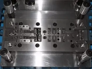
The diagrams of molds, including diagrams of parts and components, are drawn in strict accordance with the drawing standards (GB/T4457~GB/T4460 and GB/T131-1993). However, in actual production, the layout of the drawing should be adapted to the working characteristics of the mold and the requirements of installation and adjustment.
The general mold drawing includes:
(1) Main View:
A cross-sectional view of the mold in its working position is drawn. Usually, one half of the view shows the situation before the stamping process begins (when the press slider is in the upper stop position and the rough is placed), and the other half shows the state after the punch is completed, the workpiece is formed (or separated), and the press slider is in the lower stop position.
(2) Top View:
Typically, one half of the top view shows the lower half of the mold, and the other half shows the upper half. In some cases, the lower half of the top view may also be fully drawn if necessary.

(3) Side View, Elevation View, and Partial Section View:
If necessary, a side view of the mold in its working position can be drawn. In some cases, the top right corner of the drawing may also be used to show a view of the upper part of the mold and a partial section.
(4) Workpiece Diagram:
The general artifact diagram is located in the upper right corner. For work performed by multiple sets of molds, it is necessary to draw a workpiece diagram for the current process in addition to the workpiece diagram for the previous process.
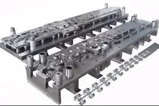
(5) Sample Diagram:
For a progressive die, it is necessary to draw the layout, the sequence of the process, and the stamping content for each step. The step spacing, edge value, and strip size should also be indicated. The layout of the die should be marked with the layout method, strip size, and overlay value size.

(6) Parts List:
A list of parts should be provided, indicating the material and quantity. Standard parts should be specified in the specifications.
(7) Technical Requirements and Description:
The technical requirements include the punching pressure, equipment type, overall mold tolerance and assembly, installation and commissioning, mold closing height, mold clearance, and other requirements.
All dimensions, tolerances and fits, shape and position tolerances, surface roughness, materials used and their heat treatment requirements, and other technical specifications should be indicated on the part drawings.
For small-scale production, a detailed process route table should be filled out, while for large-scale production, a process card should be created for each part.

As the founder of MachineMFG, I have dedicated over a decade of my career to the metalworking industry. My extensive experience has allowed me to become an expert in the fields of sheet metal fabrication, machining, mechanical engineering, and machine tools for metals. I am constantly thinking, reading, and writing about these subjects, constantly striving to stay at the forefront of my field. Let my knowledge and expertise be an asset to your business.