Pipe Bending Equipment and Calculation: Ultimate Guide
Have you ever marveled at the intricate curves and bends of industrial pipes? In this blog post, we'll explore the fascinating world of pipe bending equipment and calculations. Our expert…
Have you ever considered the forces at play when bending a pipe? In this article, we’ll explore the fascinating world of pipe bending mechanics. Our expert mechanical engineer will break down the key concepts and calculations involved, providing valuable insights for professionals and enthusiasts alike. Get ready to discover the science behind creating smooth, precise bends in pipes!
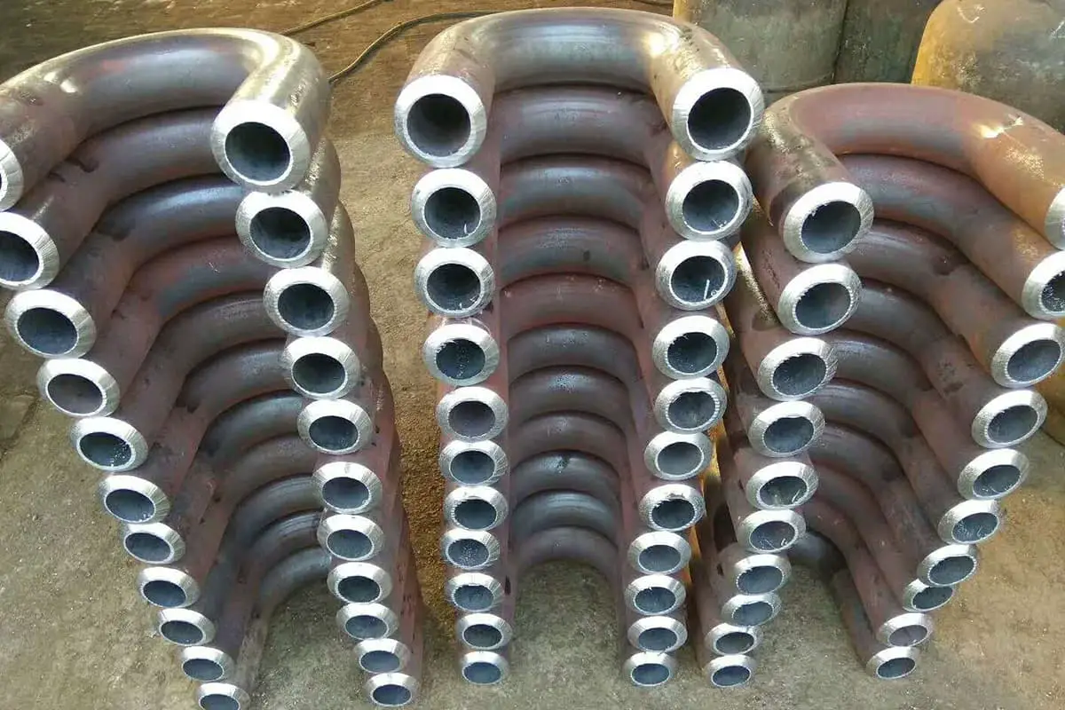
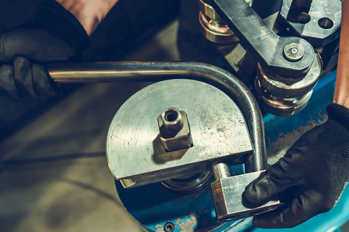
The pipe bending process has evolved significantly with the rise of various industries such as automobiles, motorcycles, bicycles, and petrochemicals. This process is essential for creating precise and durable bends in pipes used in these sectors.
Figures 6-19, 6-20, 6-21, and 6-22 respectively represent the schematic diagrams of the molds for winding, pushing, pressing, and rolling devices. These diagrams illustrate the specific setup and components used in each bending method, providing a visual reference for understanding the process.
By categorizing the pipe bending methods based on the bending technique, temperature, and use of fillers or mandrels, we can better understand the appropriate applications and advantages of each method. This knowledge is crucial for selecting the right bending process for specific industrial needs, ensuring efficiency and precision in manufacturing.

1- Pressure Block
2- Core Rod
3- Clamp Block
4- Bending Mold
5- Wrinkle Prevention Block
6- Pipe Blank

1—Press Column
2—Guide Sleeve
3—Tube Blank
4—Bending Mould

1—Die
2—Tube Blank
3—Swinging Punch

1—Axis
2,4,6—Rollers
3—Active Axis
5—Steel Pipe
When the pipe material is bent, the material on the outer side of the deformation zone is stretched and lengthened by the tangential tension, while the material on the inner side is compressed and shortened by the tangential compression.
As the tangential stress σθ and strain εθ are continuously distributed along the cross-section of the pipe material, they can be imagined as similar to the bending of the plate material.
The stretching zone on the outer side transitions to the compression zone on the inner side, with a neutral layer at the junction.
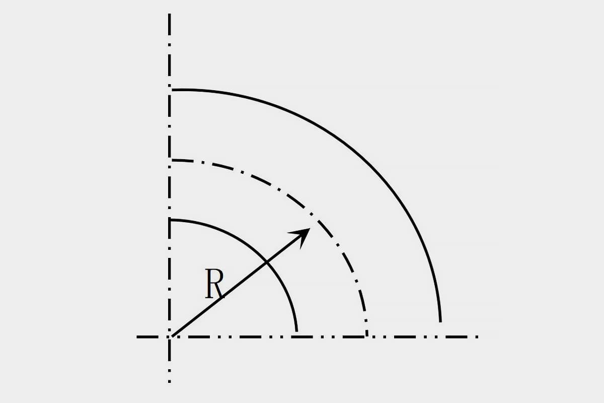
To simplify analysis and calculation, it is usually considered that the neutral layer coincides with the central layer of the pipe cross-section, and its position in the cross-section can be represented by the radius of curvature (Figure 6—23).
The degree of bending deformation of the pipe material depends on the relative bending radius R/D and relative thickness t/D (R is the radius of curvature of the central layer of the pipe cross-section, D is the outer diameter of the pipe, t is the wall thickness of the pipe).
The smaller the R/D and t/D values, the greater the degree of bending deformation (i.e., R/D and t/D are too small), the outer wall of the bending neutral layer will become excessively thin, and even lead to rupture; the innermost pipe wall will thicken, and even become unstable and wrinkled.
At the same time, with the increase in the degree of deformation, the cross-section distortion (flattening) becomes more serious.
Therefore, to ensure the forming quality of the pipe material, the degree of deformation must be controlled within the permissible range.
The allowable degree of deformation in pipe bending is called the bending forming limit. The bending forming limit of the pipe material not only depends on the mechanical properties of the material and the bending method, but also considers the usage requirements of the pipe fittings.
For general-purpose bent parts, the maximum elongation strain εmax produced at the position farthest from the neutral layer on the outer side of the pipe material bending deformation area should not exceed the limit value allowed by the material plasticity as the condition for defining the forming limit.
That is, the limit bending radius rmin that can be bent into the inner side of the part under the condition that the outer surface layer on the outer side of the pipe part bending deformation area does not crack, is used as the forming limit of the pipe part bending.
rmin is related to the mechanical properties of the material, the structural size of the pipe fittings, the bending processing method, and other factors.

a Force conditions
b Stress-strain conditions
The minimum bending radius for different bending processes can be found in Table 6-2.
Table 6-2 Minimum Bending Radius During Pipe Bending (Unit: mm)
| Bending Methods | Minimum Bending Radius |
| Press Bending | (3~5)D |
| Wrap Bending | (2~2.5)D |
| Roll Bending | 6D |
| Push Bending | (2.5~3)D |
Note: D represents the outer diameter of the tube.
For the minimum bending radius of steel and aluminum tubes, refer to Table 6-3.
Table 6-3 Minimum Bending Radius of Steel and Aluminum Tubes (Unit: mm)
| Outer Diameter of the Pipe | 4 | 6 | 8 | 10 | 12 | 14 | 16 | 18 | 20 | 22 |
| Minimum Bending Radius | 8 | 12 | 16 | 20 | 28 | 32 | 40 | 45 | 50 | 56 |
| Outer Diameter of the Pipe | 24 | 28 | 30 | 32 | 35 | 38 | 40 | 44 | 48 | 50 |
| Minimum Bending Radius | 68 | 84 | 90 | 96 | 105 | 114 | 120 | 132 | 144 | 150 |
During pipe bending, the cross-sectional shape distortion is inevitable.
The material on the outer side of the neutral layer suffers tangential tensile stress, thinning the pipe wall; the material on the inner side of the neutral layer experiences tangential compressive stress, thickening the pipe wall.
The material on the outermost and innermost sides of the bending deformation area undergoes the greatest tangential stress, hence the greatest changes in pipe wall thickness occur there (Fig 6-24).
In bending with fillers or core rods, the cross-section is basically able to maintain a circular shape, but the wall thickness changes. In unsupported free bending, whether it’s the inner edge or the outer side, the circular pipe cross-section becomes elliptical (Fig 6-24a, b).
Moreover, as the degree of bending deformation increases (i.e., the bending radius decreases), the inner edge becomes unstable and wrinkles. In the case of square tubes in supported bending (Fig 6-24c, d), the cross-section changes into a trapezoidal shape.

The ellipticity is often used in production to measure changes in the circular cross-section of a pipe.
Ellipticity= Dmax-Dmin/D ×100% (6-21)
In this formula, Dmax is the maximum outer diameter size measured in any direction of the same cross-section of the pipe after bending, and Dmin is the minimum outer diameter size measured in any direction of the same cross-section of the pipe after bending.
Figure 6-25 is an ellipticity plot, which represents the change of ellipticity corresponding to the dimensionless curvature R0/R (R0 is the outer radius of the pipe, R is the curvature radius of the center layer of the bending section) on a logarithmic coordinate, represented as a family of straight lines with the ratio t/R0 as the parameter variable.
As can be seen from the figure, the greater the degree of bending, the greater the cross-sectional ellipticity.
Therefore, ellipticity is often used in production as an important index for inspecting the quality of bent pipes. Depending on the different usage performances of bent pipe materials, the requirements for their ellipticity also vary.
For example, for bent pipe components used in industrial pipeline projects, the high-pressure pipe does not exceed 5%; medium and low-pressure pipes are 8%; aluminum pipes are 9%; and copper alloy and aluminum alloy pipes are 8%.

Section shape distortion may reduce the cross-sectional area, increasing the resistance to fluid flow, and can also affect the functional performance of the pipe in the structure.
Therefore, in the bending process of the pipe, measures must be taken to control the distortion within the required range.
Effective methods to prevent cross-sectional shape distortion are:
1) Support the cross-section with a mandrel in the bending deformation area to prevent cross-sectional distortion.
For different bending processes, different types of mandrels should be used. Rigid mandrels are often used in bending and winding, and the head of the mandrel is hemispherical or other curved surface shape.
Whether a mandrel is needed during bending, and what kind of mandrel to use, can be determined from Figure 6-26 and Figure 6-27.

2) Filling the bent tube blank with granular media, fluid media, elastic media, or low-melting-point alloys can also replace the core rod to prevent section shape distortion. This method is relatively easy to apply and is widely used, mostly for small to medium scale production.
3) On the surface of the mold in contact with the tube material, a groove is made to match the section shape of the tube material, reducing the pressure on the contact surface and hindering the distortion of the section. This is a quite effective measure to prevent section shape distortion.
4) The method of using the counter deformation method to control the change in the tube section (Figure 6-28) is often used in the coreless bending process on the pipe bender. The feature of this method is its simple structure, so it is widely used.
The use of counter deformation for coreless bending means that the tube blank is given a certain amount of reverse deformation in advance. Then, after bending, the deformation in different directions cancels each other out, basically keeping the tube blank section circular to meet the requirements of ellipticity, thus ensuring the quality of the bent pipe.

1—Bending Mold
2—Clamping Block
3—Roller
4—Guide Wheel
5—Pipe Blank
The cross-sectional shape of the anti-deformation groove as shown in Figure 6-29, the size of the anti-deformation groove is related to the relative bending radius (the curvature radius of the central layer, the outer diameter of the pipe). See Table 6-4.
Table 6-4 Dimensions of the Anti-deformation Groove
| Relative Bend Radius R/D | R1 | R2 | R3 | H |
| 1.5~2 | 0.5D | 0.95D | 0.37D | 0.56D |
| >2~3.5 | 0.5D | 1.0D | 0.4D | 0.545D |
| ≥3.5 | 0.5D | — | 0.5D | 0.5D |

1—Bending Mold
2—Anti-deformation Roller
The change in tube thickness mainly depends on the relative bending radius R/D and the relative thickness t/D. In production, the minimum wall thickness tmin on the bending outside and the maximum wall thickness tmax on the inside can usually be estimated using the following formula:

In the formula,
The thinning of tube material reduces the mechanical strength and usability of the fittings. Therefore, in production, the wall thinning rate is often used as a technical index to measure the change in wall thickness in order to meet the usability of the fittings.
Rate of pipe wall thinning = t-tmin/t×100%
In the formula:
The performance of pipe materials varies, and there are different requirements for the wall thickness reduction rate.
For example, for pipe fittings used in industrial pipe engineering, the high-pressure pipe does not exceed 10%; the medium and low-pressure pipe does not exceed 15%, and it is not less than the design calculated wall thickness.
Measures to reduce pipe thickness thinning include:
1) Reduce the numerical value of the tensile stress generated on the outside of the neutral layer. For example, using the method of resistance local heating to reduce the deformation resistance of the metal material inside the neutral layer, making the deformation more concentrated in the compressed part, achieving the purpose of reducing the stress level of the tensile part.
2) Change the stress state of the deformation zone and increase the component of compressive stress. For example, changing from bending to pushing can fundamentally overcome the defect of excessive thinning of the pipe wall.
The calculation of the bending torque of the pipe material is the basis for determining the energy parameters of the pipe bender.
According to the analysis of plastic mechanics theory, the theoretical expression of bending moment when the pipe material is uniformly bent is derived as follows:
Bending torque of pipe material:
In the formula:
The actual bending moment of the tube material not only depends on the properties of the tube material, cross-sectional shape and size, bending radius, and other parameters, but is also greatly related to the bending method and the structure of the mold used.
Therefore, it is currently impossible to represent all these factors with a calculation formula, and only estimates can be made in production.
The bending torque of the tube material can be estimated with the following formula:

In the equation,
The coefficient µ is not the friction coefficient; its value depends on the surface condition of the pipe, the bending method, especially whether a mandrel is used, the type and shape of the mandrel, and even various factors related to the position of the mandrel.
Generally speaking, when a rigid mandrel is used without lubrication, a value of 5 to 8 can be taken; when a rigid hinged mandrel is used, a value of µ=3 can be taken.
The cross-sectional shape of the anti-deformation groove is shown in Figure 6-29.
The dimensions of the anti-deformation groove are related to the relative bending radius (the curvature radius of the central layer, the outer diameter of the tube).
See Table 6-4.
Table 6-4 Dimensions of Anti-deformation Groove
| Relative bending radius R/D | R1 | R2 | R3 | H |
| 1.5~2 | 0.5D | 0.95D | 0.37D | 0.56D |
| >2~3.5 | 0.5D | 1.0D | 0.4D | 0.545D |
| ≥3.5 | 0.5D | — | 0.5D | 0.5D |

1—Bending Mold
2—Anti-deformation Roller
The change in tube thickness mainly depends on the relative bending radius R/D and the relative thickness t/D.
In production, the minimum wall thickness tmin on the outer side of the bend and the maximum wall thickness tmax on the inner side can generally be estimated using the following formula:

In the formula:
The thinning of the tube material reduces the mechanical strength and performance of the pipe fittings. Therefore, the thinning rate is often used in production as a technical indicator to measure the change in wall thickness, in order to meet the performance requirements of the pipe fittings.
Rate of pipe wall thinning = (t-tmin)/t×100%
In the formula:
Different performances of the tube material require different thinning rates. For example, for pipe fittings used in industrial pipeline engineering, the high-pressure pipe should not exceed 10%; the medium and low-pressure pipes should not exceed 15% and should not be less than the design calculation wall thickness.
Measures to reduce tube thickness thinning include:
1) Reducing the numerical value of the tensile stress generated on the outer side of the neutral layer, such as adopting the method of resistance local heating, reducing the deformation resistance of the metal material on the inner side of the neutral layer, making the deformation more concentrated in the compressed part, thus achieving the purpose of reducing the stress level of the tensile part.
2) Changing the stress state of the deformation zone and increasing the component of compressive stress. For example, changing from bending to pushing can fundamentally overcome the defect of excessive thinning of the tube wall.
The calculation of tube bending torque is the basis for determining the power parameters of the pipe bender. According to the analysis of plastic mechanics theory, the theoretical expression of the uniform bending moment of the tube is derived as follows:
Tube bending torque:

In the formula:
The actual bending moment of the tube material not only depends on the performance of the tube material, the shape and size of the cross-section, the bending radius and other parameters, but also has a lot to do with the bending method and the structure of the mold used.
Therefore, it is currently impossible to express all factors in a calculation formula, and only estimates can be made in production.
The bending moment of the tube material can be estimated with the following formula:

In the formula:
The coefficient is not the friction coefficient µ, its value depends on the surface condition of the pipe, the bending method, and especially whether a mandrel is used, the type and shape of the mandrel, and even various factors related to the position of the mandrel.
Generally speaking, when a rigid mandrel is used without lubrication, it can be taken as =5 to 8; if a rigid hinged mandrel is used, it can be taken as µ=3.
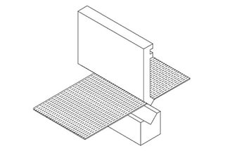
Tube rolling forming is a special forming process developed from traditional stamping flanging and necking processes. It is a deformation process in which the edge of the tube mouth is locally bent by applying axial pressure to the tube piece through the mold.
The use of this technology to manufacture parts has a series of advantages such as simple technology, fewer processes, low cost, and good quality. It can even produce parts that are hard to achieve with other stamping methods.
This process has been widely used in various industrial fields such as automobiles and aerospace.
There are two basic ways of tube turning forming, namely outer roll and inner roll (Figure 6-30).

a, b outward roll;
c, d inward roll
1—Tube blank
2—Flow guide ring
3—Cone mold
4—Round edge mold
Outward roll: The tube blank is flipped from inside to outside under axial pressure, increasing its circumference after forming.
Inward roll: The tube blank is rolled from outside to inside, reducing its circumference after forming.
The rolling process can not only effectively form various types of tubular double-wall or multi-layer parts, but also process convex bottom cups, step tubes, special-shaped tubes as well as semi-double tubes, annular double-wall cylinders, hollow double-wall nuts, heat exchangers, automobile mufflers, waveguide tubes in the electronics industry, etc.
At present, these parts are generally processed by multi-step stamping and welding methods, which are difficult, costly, and of poor appearance quality.
The use of the rolling process ensures the reliability of the part, lightweight, and saves raw materials.

Currently, according to the data, many metal materials can be formed on the mold in various different rolling methods, such as aluminum alloy, copper and copper alloys, low carbon steel, austenitic stainless steel, etc. Tube blanks of all sound specifications can successfully be rolled into double-layer tubes.
Roll forming, compared to other forming processes, has a more complex deformation process, which includes flaring, curling, rolling and their mutual conversion.
There are several molds to realize this forming process, among which the simple and commonly used ones are conical molds and fillet molds.
1. Conical tube rolling mold
The structure of the conical tube rolling mold is shown in Figure 6-32. This mold structure is simple, and different specifications of tubes can be formed on one set of molds, which is difficult to achieve on other tube forming molds.
Also, as a pre-forming process for precision tube roll forming, conical mold forming is widely used.

a Tube Flipping Mold Structure
b Conical Tube Flipping Process Parameters
1 – Press Head
2 – Tube Billet
3 – Cone Mold
During the tube turning process, one end of the tube blank is placed on a conical die, while the other end is subjected to axial pressure from the press slider to achieve the tube blank turning.
When designing this type of die, the half-cone angle α of the die is the most critical parameter.
The size of α not only determines the feasibility of tube turning, but also affects the geometric dimensions of the tube turning, that is, the tube turning coefficient K(K=D/D1, where D and D1 are the outer diameter of the tube blank and the outer diameter of the tube turning, respectively).
Obviously, there exists a critical half-cone angle α0, and the turning can be carried out normally only when the half-cone angle α≥ α0.
µ, H, Golubnov derived based on the principle of principal stress:

Considering the influence of material strengthening and the rigidity of the flared end, the above formula can be modified as follows:

In the formula:

For a 42mm 3A21 aluminum tube, calculated by the above formula, the angle is 55° – 60°.
Empirical tests show that when the angle is α≥60° (α≈68°), the tube flipping can proceed smoothly. At this time, the axial pressure is the smallest.
When the angle is 55° – 60°, the end of the tube blank curls but does not enter the flipping stage. When the angle is α<55°, the tube end only flares on the cone die and does not curl.
During the cone die flipping, the tube end easily slides, causing the flipped part of the tube to be off-axis with the original tube blank and causing axial bending during the flipping.
It’s hard to get a double-layer flipped tube part that meets the assembly quality requirements. Hence, a round corner flipping die was developed based on the cone die.
2. Round Corner Flipping Die
The round corner flipping die uses the die’s working part, which is a radius circle, to force the axially compressed tube end to deform along its arc to achieve tube flipping.
Figure 6-33 shows a schematic diagram of a tube blank with a thickness of t and an average diameter of D, rolling on a round corner die with a radius of r, under axial load, the tube end curls upwards along the die’s arc to get a rolled tube piece with a diameter of D1.
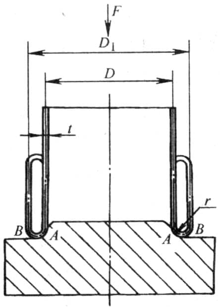
The most important parameter in designing a round corner flanging die is the radius r of the die’s corner. It determines not only the geometric dimensions of the flanged part, but also influences the magnitude of the flanging force.
For the 3A21 annealed aluminum tube of type Φ41×1, both theoretical analysis and experimental results show that the critical die fillet radius (minimum fillet radius) for tube inversion instability is about 2mm; the optimal fillet radius is approximately 3mm; the maximum fillet radius is around 4mm.
This indicates that the stability and quality of tube inversion under axial load depend on the die fillet radius r. If r is less than a certain critical value, the tube end does not curl along the die arc; when r is too large, the tube end fractures and cannot be successfully inverted. Only when r is within an appropriate range can the tube inversion be realized.
Similar to the outward curling of the tube material, the inward curling of the tube can also be carried out on the cone mold and the fillet mold (Figure 6-34).
Compared to other forming processes, it is prone to instability. Because during the inward curling, the diameter of the tube decreases after deformation, the tube wall thickens, the tube inversion force increases, which brings difficulties to the curling forming.
According to theoretical calculations and practice, when the critical semi-cone angle β of the tube inversion cone mold is ≥120°, the curling process can proceed smoothly. In production, the value is usually taken as β≥120°~125°, rp≈4mm.
The tube curling process can only occur when the load required for curling is less than the axial instability limit. Since the curling forming load largely depends on the geometric parameters of the mold, in terms of the fillet mold, it depends on the fillet radius r.
Therefore, a feasible region for curling forming can be determined (Figure 6-35).

a Conical Die
b Rounded Die

From Figure 6-35, it can be seen that the area for internal rolling is quite small, and the rolling load is numerically higher than that of external rolling, almost reaching 50%.
Existing data shows that both domestically and internationally, the optimal process parameters for external rolling have been studied theoretically and practically, and the relationship between the minimum axial compressive stress required for complete rolling, and the inner diameter, outer diameter, and wall thickness of the tubular material has been discovered.
During the external rolling of tubular materials, the change in wall thickness is not significant.
However, during internal rolling, the circumferential compressive stress causes the wall thickness at the mold fillet to continuously increase until it reaches a constant value, which can be 1.5 times the original thickness. Therefore, to complete its internal rolling, a larger axial load is required.
In the aforementioned two types of rolling (traditional rolling), there are some shortcomings:
1. The beginning of the second layer of the tube wall is not parallel to the original tube wall, but always turns towards the inner cavity of the double-wall tube;
2. There is a certain distance between the new tube wall and the original tube wall, which depends on the relative diameter(D/t) of the original tube material;
3. For internal rolling, the second layer of the tube wall is considerably thicker, which in turn leads to an increase in axial pressure during rolling.
The issues that arise in the aforementioned processes are due to the forming mechanism, which limits the geometric shape of the obtained tubes, especially the poor stability and high difficulty of the internal rolling process, which needs to be improved.
Therefore, the tensile stress rolling forming method for internal rolling of tubular materials has emerged.
The characteristic of the tensile stress rolling forming method is that it stops rolling in the first stage of internal rolling of the tubular material, and gives the rolled edge a reverse bend, directing it towards the outside of the cavity.
Then, through the action of the convex mold, the tensile force acting on the reverse bend edge on the inner wall causes the tube blank to undergo internal rolling, rather than rolling by the axial pressure acting on the outer wall, thereby reducing its axial pressure.
This process can achieve a larger inner wall height, constant wall thickness, and higher product accuracy.
The tensile stress rolling forming method has expanded the application range of the internal rolling forming process, such as the production of pipe joints, rolling bearing seats, and others (Figure 6-36).

The tensile stress roll forming method can be divided into three steps as shown in Figure 6-37.
In the first step (Figure 6-37a), traditional inner rolling ends when the edge of the tube leaves a quarter of the fillet die.
At this time, the distance between the edge of the tube and the inner wall of the die will form the radial support of the final product and must be equal to the required width.
In the second step (Figure 6-37b), the flat-bottom convex die descends, forcing the edge of the tube to flange (similar to the hole flanging of the plate). The gap between the convex die and the inner roll die is determined by the tube wall thickness (the tube inner roll wall thickness is slightly increased).
In the third step (Figure 6-37c, d), the forming convex die rises, causing the edge of the tube to roll inward, thus generating the second layer of tube wall under the push of the forming convex die.
As can be seen from the figure, the forming convex die acts on the edge of the tube with tensile stress, not compressive stress acting on the entire tube.
There is no relative sliding between the die and the deformed material, and a distance is maintained between the forming loads, thereby reducing the axial compressive stress on the tube transmission area, thus preventing instability.
Therefore, tensile stress rolling has greater freedom in choosing the rolling radius, while the die radius is an important process parameter in traditional machining processes (Figure 6-35).

Conditions for the successful execution of this process:
FPunching Hole≥FRolling (6-22)
The punching force includes three components (symbol in Figure 6-37d): the load causing plastic deformation of the material at radius rP; the load required to overcome the friction at corner ra between the punch and the edge of the tube; the load required for bending and unbending the edge material from the radial to axial position.
In the analytical expression, σ1 is used to represent the internal wall deformation stress.
Then,

Roll forming includes two aspects: the load required for material rolling to different curvature radii positions and the load required for bending and rebounding from the beginning to the end of the deformation zone.
In the analysis, σ0 is used to represent the deformation stress of the outer wall, and σm represents the average plastic deformation stress in the deformation zone.

Conclusion:
The method of forming the tube by rolling under tensile stress has been proven through experiments.
Although two preparation stages are required before the start of rolling and recrystallization annealing is needed when necessary, it has the following advantages compared to the traditional rolling process:
1) The rolled edge turns towards the center of the cavity, making it easy to coordinate with other parts, such as ball bearing seats.
2) The rolling load is significantly reduced.
3) The forming limit is greatly improved, and products with a smaller rolling radius can be obtained.
4) There is no friction and no need for lubrication.
5) The inner wall thickness is approximately equal to the outer wall thickness, and only the edge under load is slightly thicker (Figure 6-38).
The experimental conditions of the part shown in Figure 6-38 are as follows:
The tube is made of low carbon steel, Dout = 90mm, t0= 2.4mm, H =150mm.
The diameter of the concave die (Figure 6-37d) is Dd = 97mm.
The diameter of the convex die (Figure 6-37d) is Dp =72mm.
6) Because of the absence of friction and the double constraint of the convex and concave dies on the wall of the part, the part has a high dimensional accuracy (Figure 6-37d).
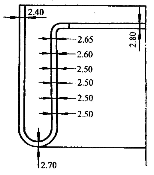
Figure 6-37 Tensile Stress Roll Forming Process (Improved Inward Forming Process)
Conditions for the successful implementation of this process:
FPunching Hole≥FRolling (6-22)
The punching force includes three items (symbol in Figure 6-37d): the load that causes plastic deformation of the material at radius rp; the load required to overcome the frictional force between the punch corner at ra and the edge of the tube; the load required for bending and reverse bending of the edge material from the radial to the axial position.
In the analytical expression, σ1 represents the deformation stress of the inner wall.

Roll forming includes two aspects: the load required for the material to roll to different (curvature) radius positions, and the load required for bending and reverse bending from the beginning to the end of the deformation area.
In the analysis, σ0 is used to represent the deformation stress of the outer wall, and σm is used to represent the average plastic deformation stress in the deformation area.

Conclusion:
The method of forming pipe materials by tensile stress rolling has been proven by experiments. Although two preparation stages are needed before the start of rolling and recrystallization annealing is necessary when needed, it has the following advantages over traditional rolling processes:
1) The rolled edge turns towards the center of the cavity, making it easy to cooperate with other parts, such as ball bearing seats.
2) The rolling load is greatly reduced.
3) The forming limit is greatly improved, and products with smaller rolling radii can be obtained.
4) There is no friction and no need for lubrication.
5) The thickness of the inner wall is approximately equal to that of the outer wall, and only the edges under load are slightly thicker (Figure 6-38).
The experimental conditions of the parts shown in Figure 6-38 are as follows:
The pipe material is low carbon steel, Dout = 90mm, t0 = 2.4mm, and the radius H is 150mm.
The die diameter Dd (Figure 6-37d) is 97mm.
The punch diameter (Figure 6-37d) is Dp =72mm.
6) Due to the absence of friction and the double constraints of the punch and die on the wall of the part, the part has higher dimensional accuracy (Figure 6-37d).


As the founder of MachineMFG, I have dedicated over a decade of my career to the metalworking industry. My extensive experience has allowed me to become an expert in the fields of sheet metal fabrication, machining, mechanical engineering, and machine tools for metals. I am constantly thinking, reading, and writing about these subjects, constantly striving to stay at the forefront of my field. Let my knowledge and expertise be an asset to your business.