Pose perception is achieved through the combined use of non-contact position sensors and attitude sensors to track changes in an object’s spatial position and orientation.
1) Non-contact Position Sensors
Unlike contact position sensors, non-contact position sensors are designed and manufactured using technologies such as the Hall effect, magnetoresistance, electromagnetic induction principles, and capacitance principles. These sensors do not experience relative friction, thus enhancing their lifespan.
Over the past several decades, potentiometers have been used for position and angle measurements because of their simple design, mature manufacturing technology, and low cost.
However, their inherent limitations have also hindered their development. Renowned international auto parts manufacturers began dedicating research and development efforts to non-contact position sensors over a decade ago.
2) Inductive Position Sensors
Inductive position sensors operate based on the principle of electromagnetic induction, which generates an induced current in a conductor that is part of a closed circuit when it moves to cut magnetic field lines.
Similar to other angle sensors, they consist of a stator and a rotor. There are generally two types of inductive position sensors.
The first type is the coil winding type, which requires a large iron core to wind the inductive coil. This type is large in size, complex in structure, and requires a back-end signal conditioning circuit.
Despite its high measurement accuracy, it is relatively expensive and is currently mainly used for torque measurement in EPS systems, with products of this type available from both KOYO and NSK.
The second type is the planar coil type. The stator of a planar coil inductive sensor consists of planar excitation, receiving coils, and electronic components, including a standard PCB and ASIC.
The rotor is made from a stamped piece of conductive wire with a specific geometric shape (either made from conductive material or PCB components).
At present, position sensors developed by the German company Hella using planar coil position sensor technology are widely used for angle feedback in throttle pedals and actuators.
Planar coil position sensors have a relatively simple design structure. The stator on the PCB consists of an excitation coil, three inductive receiving coils, and other signal processing electronic components, while the rotor is a simple stamped metal piece.
The key to inductive position sensors lies not in the design of planar coil graphics but in custom chip technology.
The signal processing unit of the chip accepts voltage signals from the coil, rectifies and amplifies them, and proportionally outputs them in pairs.
The output signals include analog signals, pulse modulation signals, and bus communications. They can operate within a temperature range of -40 to +50 degrees Celsius and withstand vibrations up to 30g, demonstrating excellent reliability, longevity, and humidity resistance.
They can also function under various forms of electromagnetic fields. The manufacturing challenges of inductive position sensors lie in the level of chemical etching techniques for planar coils and the packaging technology of the custom signal processing unit.
Without the use of custom chips, the costs would be significantly higher.
Inductive position sensors offer the following advantages: they are minimally affected by mechanical tolerances, require no temperature compensation settings, need no additional magnetic materials, and are immune to interference from magnetic fields and electrical signals.
They can meet all requirements for electromagnetic compatibility in automobiles, measure angles up to 360 degrees or even more, and are highly flexible.
They can measure both angular displacement and linear displacement. The sensors maintain an accuracy within 1% throughout their lifespan and across the entire temperature range.
In electromechanical devices, this technology can integrate the sensors with other electronic components on the same PCB.
The simple layout of Hella sensors is one of their greatest strengths, as integrating them into control units requires no additional casings or wiring harnesses. This simplifies the wiring and reduces connectors, further enhancing reliability.
3) Attitude Sensors
Attitude sensors are high-performance three-dimensional motion posture measurement systems based on MEMS technology.
They encompass auxiliary motion sensors such as three-axis gyroscopes, three-axis accelerometers, and three-axis electronic compasses, which output calibrated angular velocity, acceleration, and magnetic data through an embedded low-power ARM processor.
The system measures motion posture using sensor data algorithms based on quaternions and outputs real-time zero-drift three-dimensional posture data represented in quaternions and Euler angles.
Attitude sensors are widely used in products and devices that require low-cost, high-dynamic three-dimensional posture measurement, such as model aircraft drones, robots, antenna platforms, concentrated solar power, ground and underwater equipment, virtual reality, and human motion analysis.
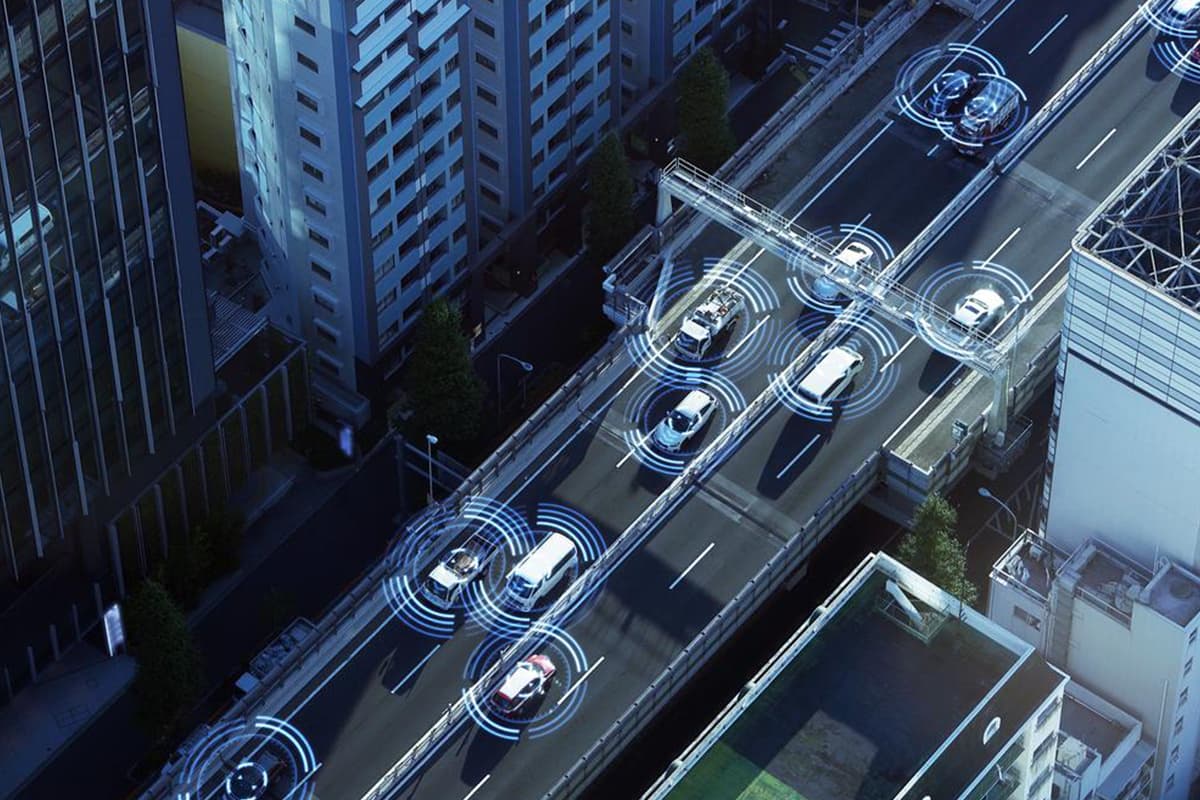
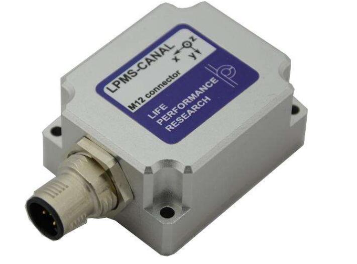
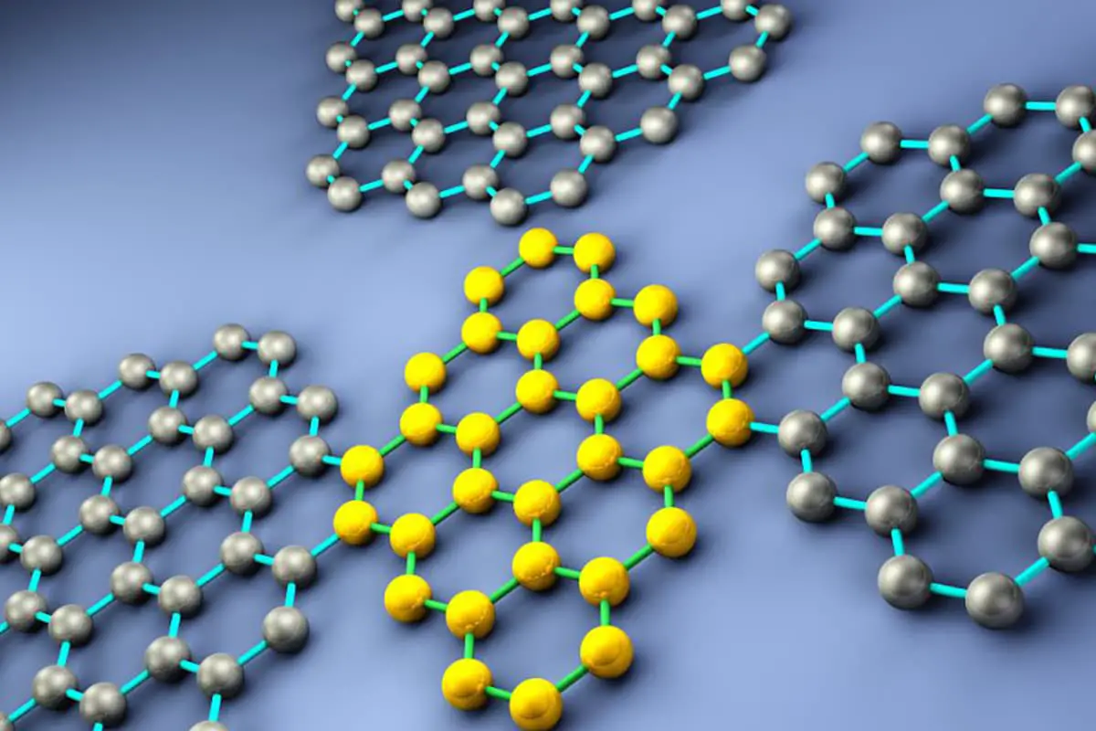
A gyroscope is a device that detects angular motion around one or two axes orthogonal to the spin axis, using the momentum of a high-speed rotating body and its sensitive shell relative to inertial space.
Devices that serve the same function, but are made using other principles, are also referred to as gyroscopes. (Figure 1)
2. Flexible Sensing
Currently, a variety of sensors are extensively employed in many intelligent detection devices. Their applications have permeated fields such as industrial production, ocean exploration, environmental protection, medical diagnosis, bioengineering, space development, and smart homes.
As the demands of the information age escalate, expectations for performance parameters like the scope, precision, and stability of the measured information are gradually increasing.
This has presented new challenges for standard sensors, especially in terms of measuring requirements for gas, pressure, and humidity under special environments and signals.
In response to the increasing number of special signals and environments, new sensor technologies have developed in the following trends: the development of new materials, new processes, and innovative sensors; the realization of sensor integration and intelligence; miniaturization of sensor technology hardware systems and components; and the integration of sensors with other disciplines.
At the same time, there is a desire for sensors with transparency, flexibility, extensibility, free bending or even folding capabilities, portability, and wearability. With the advancement of flexible substrate materials, flexible sensors that meet all these trend characteristics have emerged accordingly.
1) Characteristics of Flexible Sensors
Flexible materials, in contrast to rigid ones, typically exhibit properties such as softness, low modulus, and ease of deformation. Common flexible materials include polyvinyl alcohol (PVA), polyester (PET), polyimide (PI), polyethylene naphthalate (PEN), paper sheets, and textile materials.
Flexible sensors are those made from these flexible materials, offering excellent flexibility, extensibility, and even the capability to freely bend or fold.
With diverse structural designs, they can be arranged as needed, depending on the measurement conditions, facilitating the convenient inspection of complex subjects.
These novel flexible sensors are widely utilized in diverse fields such as electronic skin, healthcare, electronics, electrical engineering, sports equipment, textiles, aerospace, and environmental monitoring.
2) Classification of Flexible Sensors
Flexible sensors are diverse, with various categorization methods. Classified by use, flexible sensors include pressure sensors, gas sensors (for alcohol detection), humidity sensors (for weather forecasting), temperature sensors (like thermometers), strain sensors, magnetoresistive sensors, and thermal flow sensors (for refrigerators).
Classified by detection mechanism, flexible sensors include resistive, capacitive, magnetopressive, and inductive types.
3) Common Flexible Sensors
(1) Flexible Gas Sensors
Flexible gas sensors utilize gas-sensitive thin film materials arranged on the electrode surface, with a flexible substrate.
They are characterized by lightness, flexibility, the ability to bend easily, and the potential for large-scale production. The thin film materials are noted for their high sensitivity and relatively simple fabrication process, garnering significant attention.
This fully satisfies the portability and low power requirements of gas sensors in special environments, overcoming the traditional limitations of gas sensors, such as their lack of portability, incomplete measurement range, small scale, and high cost. They can conduct simple and precise detection of NH, NO, and ethanol gases, thus attracting widespread attention.
(2) Flexible Pressure Sensors
Flexible pressure sensors are widely used in areas such as smart clothing, intelligent sports, and robotic “skin”.
Polyvinylidene fluoride, silicone rubber, and polyimide, used as their base materials, have been broadly employed in the manufacturing of flexible pressure sensors.
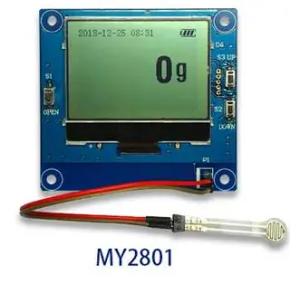
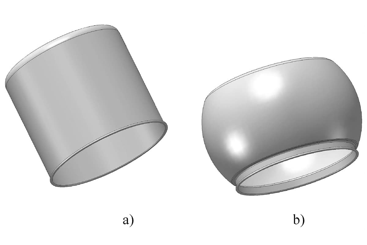
These materials distinguish themselves from force sensors using metal strain gauges and common diffusion pressure sensors using n-type semiconductor chips, by offering superior flexibility, conductivity, and piezoresistive characteristics. (Figure 2)
Figure 2: Flexible Pressure Sensor
(3) Flexible humidity sensor
Humidity sensors primarily consist of two types: resistive and capacitive. Hygrometers, characterized by a moisture-sensitive layer coated on the substrate, experience changes in resistance and resistivity as water vapor in the air is absorbed on the moisture-sensitive film.
This property can be utilized to measure humidity. Hygroscopic capacitors are generally made of polymer films, with common materials including polystyrene, polyimide, and cellulose acetate butyrate.
Humidity sensors are rapidly evolving from simple hygroscopic components to integrated, intelligent, and multi-parameter detection devices. Traditional dry and wet bulb hygrometers or hair hygrometers are no longer capable of meeting the needs of modern science.
Flexible humidity sensors, due to their low cost, low energy consumption, ease of manufacturing, and integration into smart systems, have been widely researched.
The base material for making such flexible humidity sensors is similar to other flexible sensors, and there are many methods for making the humidity-sensitive film, including dip coating, spin coating, screen printing, and inkjet printing.
Flexible sensor structures are versatile and can be arranged to meet the requirements of measurement conditions. They can conveniently and accurately measure special environments and signals, solving the problems of miniaturization, integration, and intelligent development of sensors.
These novel flexible sensors play a crucial role in electronic skin, biomedicine, wearable electronic products, and aerospace. However, the current level of technology for preparing materials such as carbon nanotubes and graphene for flexible sensors is immature, and issues related to cost, application range, and lifespan persist.
Common flexible substrates are not heat-resistant, which leads to high stress and weak adhesion between the flexible substrate and the film material. The techniques for assembling, arranging, integrating, and packaging flexible sensors also need further improvement.
4) Common Materials for Flexible Sensors
(1) Flexible substrates
To meet the needs of flexible electronic devices, properties such as lightness, transparency, flexibility, stretchability, insulation, and corrosion resistance have become key indicators for flexible substrates.
Among the many choices of flexible substrates, polydimethylsiloxane (PDMS) has become the top choice. Its advantages include easy availability, stable chemical properties, transparency, and good thermal stability.
Especially, its property of having distinct adhesive and non-adhesive areas under ultraviolet light makes it easy for electronic materials to adhere to its surface.
Many flexible electronic devices achieve significant bendability by reducing the thickness of the substrate; however, this method is limited to nearly flat substrate surfaces. In contrast, stretchable electronic devices can adhere completely to complex and uneven surfaces.
Currently, there are usually two strategies to achieve the stretchability of wearable sensors.
The first method is to directly adhere thin conductive materials with low Young’s modulus to the flexible substrate; the second method is to use inherently stretchable conductors to assemble devices, usually prepared by mixing conductive materials into an elastic base.
(2) Metallic Materials
Typically comprising conductive materials like gold, silver, and copper, metallic materials are primarily used for electrodes and conductors.
In modern printing processes, conductive materials often employ conductive nano-inks, including nanoparticles and nanowires. In addition to excellent conductivity, metal nanoparticles can be sintered into thin films or wires.
(3) Inorganic Semiconductor Materials
Represented by ZnO and ZnS, inorganic semiconductor materials show broad application prospects in the field of wearable flexible electronic sensors due to their outstanding piezoelectric properties.
(4) Organic Materials
Large-scale pressure sensor arrays are crucial for the future development of wearable sensors. Pressure sensors based on piezoresistive and capacitive signal mechanisms suffer from signal crosstalk, leading to inaccurate measurements.
This issue represents one of the greatest challenges in the advancement of wearable sensors. The use of transistors offers a solution for reducing signal crosstalk.
Consequently, many studies in the field of wearable sensors and artificial intelligence focus on how to obtain large-scale flexible pressure-sensitive transistors.
5) Application of Flexible Sensors
Flexible electronics span many fields, including the flexible foldable phone released by Huawei that employs flexible electronic technology.
Typically, flexible electronics are fabricated from a blend of organic and inorganic materials, exhibiting excellent flexibility. Flexible sensors, made from flexible materials, display impressive environmental adaptability.
As the Internet of Things and artificial intelligence evolve, many flexible sensors are characterized by their high integration and intelligent features.
The advantages of flexible sensors present promising application prospects, including in medical electronics, environmental monitoring, and wearables.
For instance, in the domain of environmental monitoring, scientists can place flexible sensors in devices to monitor the intensity of typhoons and storms.
In terms of wearables, flexible electronic products are more adept at testing skin-related parameters, given the non-flat nature of the human body.
Flexible pressure sensors are widely used in smart clothing, intelligent sports, and robotic “skin”. Polyvinylidene fluoride, silicone rubber, and polyimide, which serve as the base materials, have been extensively applied in the manufacturing of flexible pressure sensors.
These materials differ from force sensors that use metal strain gauges and general pressure sensors that use n-type semiconductor chips, showcasing superior flexibility, conductivity, and piezoresistive properties.
Jianping Yu and his team proposed a novel three-dimensional flexible capacitive tactile sensor array capable of simultaneous pressure and shear force measurement.
With the inductive electrode layer based on flexible printed circuit boards (FPCB) and the floating electrode layer based on Polydimethylsiloxane (PDMS), the fragile interface circuit is processed on the inductive electrode layer at the bottom, significantly enhancing the flexural rigidity of the sensor array.
The conductive knitted fabric formed by coating carbon-based conductive composite materials on knitted fabric, as developed by Weijing Yi and his team, exhibits pronounced piezoresistive performance.
The pressure and resistance relationship of this conductive knitted fabric within the pressure range presents a good linear relationship and excellent repeatability.
This fabric can be used for pressure measurement in smart clothing, flexible mannequins, and more, bearing significance for wearable device research. The floating-gate memory, fabricated using PEN as the flexible substrate and organic materials as the conductive layer, possesses excellent performance, and the resulting flexible pressure sensing array also has high resolution.
SOHM and others have created flexible pressure sensors by embedding PDMS electrode layers in vertically aligned carbon nanotube arrays, which can simulate tactile sensing functions and be used for robotic “skin” research.
3. Workpiece Perception and Identification
Identification of workpieces is an indispensable step in industrial manufacturing. The primary goal is to discern whether the workpieces or blanks being fed into the machine tools for processing are indeed the intended workpieces or blanks, as well as identifying their current positional information.
In small-scale operations or industries with low automation requirements, this detection and identification of workpieces can be executed manually.
However, in large-scale industrial manufacturing or flexible automated manufacturing systems, numerous different workpieces are automatically routed into various processing devices within the system, necessitating automatic detection and identification.
The combination of computer vision and artificial intelligence for automatic workpiece identification and detection is an essential area of current research.
According to statistics, over 80% of the information humans process comes from visual input, making visual sensors advantageous in multiple ways for acquiring workspace and workpiece information:
(1) Even after discarding a significant portion of the visual data, the remaining information about the surrounding environment is often more abundant and accurate than that provided by LIDAR or ultrasonic sensors.
(2) LIDAR and ultrasonic sensors operate by actively emitting pulses and receiving reflected pulses for distance measurement. Thus, when multiple workpieces are present on a workbench simultaneously, there could be interference between them. However, this problem does not exist with visual measurements, which are passive.
(3) The sampling period for data from LIDAR and ultrasonic sensors is generally longer than that of cameras, making them less efficient for providing information to high-speed robots. On the contrary, visual sensors offer considerably faster sampling rates.
Certainly, visual sensors have their drawbacks, such as being less effective than active sensors like millimeter-wave radar during foggy conditions, direct sunlight, and at night.
Active sensors can directly measure parameters such as the distance and speed of a target, while visual sensors require computation to obtain these.
However, in structured environments like laboratories and automated production workshops, the dual advantages of visual sensors in terms of information capacity and collection speed will undoubtedly play a crucial role in the development of automatic workpiece detection and recognition.
With the continuous improvement of computer performance and rapid development and perfection of computer vision technology, utilizing computers to recognize targets in images has become a research hotspot.
Furthermore, the widespread adoption of high-speed hardware implementation methods has enabled real-time image recognition technology to be better applied in practice.
Therefore, using computer vision combined with artificial intelligence to achieve automatic detection and recognition of workpieces holds significant practical significance.
The initial phase of workpiece inspection and identification relied primarily on manual methods. However, with the continuous acceleration of online speeds and escalating demands for workpiece inspection and identification, manual methods have become increasingly inadequate for industrial requirements.
This has led to the emergence of numerous innovative technologies to fulfill the needs of workpiece inspection and identification, such as eddy current detection, infrared inspection, ultrasonic testing, radiographic testing, holography inspection, and machine vision inspection technologies.
These technologies have infused new vitality into workpiece inspection and identification, significantly enhancing the level of automation.
Among these emerging technologies, the machine vision system has gained the most widespread application owing to its ability to acquire abundant and accurate information.
For example, vision assistance in robot assembly can identify the dimensions and shapes of components to ensure the correctness and quality control of the assembly.
Furthermore, based on the information recognized by vision, products can be loaded and unloaded using automated logistics systems.
This enables the identification of workpieces in rapid motion, determination of an object’s position and orientation relative to coordinates, completion of object positioning and categorization, recognition of object’s positional distance and attitude angle, extraction of prescribed parameter features, and error detection.
Presently, the identification of workpieces predominantly employs calibration methods based on traditional cameras.
From the perspective of computational thinking, traditional camera calibration methods can be categorized into four types: calibration methods using optimization algorithms, methods utilizing the camera transformation matrix, the two-step method considering distortion compensation, and the dual-plane calibration method employing a more rational camera imaging model.
Based on the characteristics of the solution algorithms, these methods can also be divided into direct nonlinear minimization methods (iterative methods), closed-form solution methods, and two-step methods.
These types of camera calibration methods assume a highly complex optical imaging model. They incorporate various factors in the imaging process and obtain camera model parameters by solving linear equations.
However, this method completely ignores the nonlinear distortion in the camera process. To improve calibration accuracy, the application of nonlinear optimization algorithms is inevitable.
This method has two main drawbacks: first, the result of camera calibration depends on the initial value given to the camera.
If the initial value is inappropriate, it is difficult to obtain the correct calibration result through the optimization program. Second, the optimization process is time-consuming and cannot yield real-time calibration results.
Dainis and Juberts proposed a method that uses direct linear transformation and introduces nonlinear distortion factors for camera calibration. Their system is designed to accurately measure the trajectory of a robot.
The system can measure the robot’s trajectory in real time, but it does not require that the calibration algorithm provides real-time calibration for the system.
(2) Utilizing the calibration method of the camera transformation matrix
Traditional methods in photogrammetry suggest that the equation describing the relationship between the three-dimensional spatial coordinate system and the two-dimensional image coordinate system is generally a nonlinear equation of the camera’s internal and external parameters.
If we neglect the nonlinear distortion of the camera lens and treat the elements in the perspective transformation matrix as unknowns, a set of three-dimensional control points and corresponding image points can be used to solve for each element in the perspective transformation matrix through a linear method.
The advantage of this type of calibration method is that it does not require the use of optimization methods to solve for the camera’s parameters, thus allowing for faster computation and real-time calculation of camera parameters.
However, there are still some shortcomings: Firstly, the calibration process does not consider the nonlinear distortion of the camera lens, affecting calibration accuracy.
Secondly, the number of unknown parameters in the linear equation exceeds the number of independent camera model parameters to be solved, meaning the unknowns in the linear equation are not mutually independent.
This over-parameterization problem means that in situations where the image contains noise, the solution to the unknowns in the linear equation may fit the set of linear equations well, but the parameters derived from this may not necessarily align well with the actual situation.
The camera calibration method using the perspective transformation matrix has been widely applied in actual systems, achieving satisfactory results.
(3) Two-step method
The idea of this calibration method is to first use the direct linear transformation method or the perspective transformation matrix method to solve for the camera parameters.
Then, using the obtained parameters as initial values, distortion factors are considered and optimization algorithms are used to further improve calibration accuracy.
As the founder of MachineMFG, I have dedicated over a decade of my career to the metalworking industry. My extensive experience has allowed me to become an expert in the fields of sheet metal fabrication, machining, mechanical engineering, and machine tools for metals. I am constantly thinking, reading, and writing about these subjects, constantly striving to stay at the forefront of my field. Let my knowledge and expertise be an asset to your business.
Basic Concepts of Computer-Aided Design and Computer-Aided Manufacturing Computer-aided design and computer-aided manufacturing (CAD/CAM) is a comprehensive and technically complex system engineering discipline that incorporates diverse fields such as computer [...]
Concept of Virtual Manufacturing Virtual Manufacturing (VM) is the fundamental realization of the actual manufacturing process on a computer. It utilizes computer simulation and virtual reality technologies, supported by high-performance [...]
A Flexible Manufacturing System (FMS) typically employs principles of systems engineering and group technology. It connects Computer Numerical Control (CNC) machine tools (processing centers), coordinate measuring machines, material transport systems, [...]
Just as manufacturing technology plays a crucial role in various fields today, nanofabrication technology holds a key position in the realms of nanotechnology. Nanofabrication technology encompasses numerous methods including mechanical [...]
Ultra-precision machining refers to precision manufacturing processes that achieve extremely high levels of accuracy and surface quality. Its definition is relative, changing with technological advancements. Currently, this technique can achieve [...]
Currently, machining can be categorized into two groups based on production batch: Among these two categories, the first one accounts for about 70-80% of the total output value of machining [...]
This article mainly introduces several mature special processing methods. I. Electrical Discharge Machining (EDM) EDM is a method of machining conductive materials by utilizing the phenomenon of electrical corrosion during [...]
What is CNC machining? Numerical Control (NC) refers to the method of controlling the movement and processing operations of machine tools using digitized information. Numerical Control Machine Tools, often abbreviated [...]
Cutting machining remains the most prominent method of mechanical processing, holding a significant role in mechanical manufacturing. With the advancement of manufacturing technology, cutting machining technology underwent substantial progress towards [...]
1. What is welding stress Welding stress refers to the stress generated during the welding process in welded components. This stress is caused by the thermal process of welding and [...]
Advanced materials refer to those recently researched or under development that possess exceptional performance and special functionalities. These materials are of paramount significance to the advancement of science and technology, [...]
Bulge forming is suitable for various types of blanks, such as deep-drawn cups, cut tubes, and rolled conical weldments. Classification by bulge forming medium Bulge forming methods can be categorized [...]