Plate Rolling Procedure: Step-by-Step Operation Guide
Have you ever wondered how skilled operators bend steel plates into perfect cylinders? In this captivating blog post, we’ll take you behind the scenes to explore the art and science of plate rolling. Our expert mechanical engineer will guide you through the intricate process, sharing insider tips and fascinating insights. Get ready to discover the secrets behind creating flawless cylindrical shapes using state-of-the-art machinery and time-honored techniques.
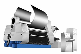
To perform the rolling operation on a roll bending machine (also known as a plate roll or rolling machine), it’s essential that the operator is well-versed in the machine’s structure and operation.
The rolling process typically requires two operators: one to control the machine and oversee the overall process, and another to assist with material handling and guidance. Both operators must work in coordination to achieve a precise and efficient rolling process for the workpiece.
Equipment Check
Before using the rolling machine, it is crucial to perform a thorough inspection:
Start up the machine and verify that the hydraulic system pressure is within the normal operating range.
Check if the side support (sometimes called the “overturned side” or “drop-end”) can be opened and closed smoothly.
Ensure that all rollers, especially the bottom roller, rotate freely and correctly. This confirms that the drive system is functioning properly.
Commissioning Plate Rolls
Conduct a visual inspection and make necessary adjustments to ensure both the upper and bottom rollers are parallel to each other. This is critical for achieving uniform bending along the length of the workpiece.
Adjust the center distance between rollers according to the material thickness and desired bend radius. Refer to the machine’s specifications and rolling charts for proper settings.
Material Considerations
When rolling a steel plate, ensure that its parameters fall within the machine’s capabilities:
Yield strength of the material
Minimum allowed rolling diameter
Width and thickness of the plate
Machine capacity (force and torque)
The surface quality of the steel plate must meet the following criteria:
Smooth surface without noticeable defects along the cutting edges
Flat and clean, free from scale or deep scratches that could affect the rolling quality
Material Preparation
Before rolling, consider the following material preparation steps:
For medium-carbon steels (e.g., 45# steel or AISI 1045), annealing of the entire plate may be necessary to improve formability and reduce the risk of cracking during bending.
Low-carbon steels generally do not require heat treatment before rolling, as they are typically more ductile and easier to form.
Always consult material specifications and engineering guidelines for proper preparation of specific steel grades.
Pre-Bending Process for Roll Bending Machine
Alignment
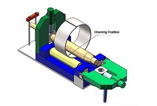
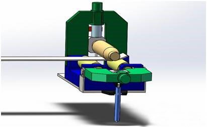
Positioning the Plate: Place the plate on the roll bending machine.
Visual Alignment: Align the upper roller edge parallel with the cutting edge of the plate using visual methods.
Error Margin: Ensure that any alignment error is within the range of ±0.5mm.
Rolling Circular
Initial Pressure Application:
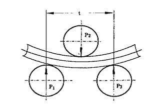
Apply a continuous pressure of 15mm on the upper roller’s outer circle against the plate’s surface.
Control the rotation of the bottom roller using a jog control.
Stop the rotation of the bottom roller when the plate’s arc length reaches between 600-800mm.
Subsequent Pressure Application:
Apply a pressure of 10mm on the upper roller.
Rotate the bottom roller and stop it when the end of the plate becomes tangent to the bottom roller.
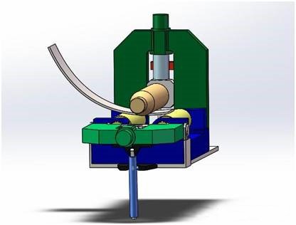
Repetition for Desired Arc Length:
Repeat the process of pressing the upper roller and rotating the bottom roller.
Continue until the arc length of the pre-bending sheet matches the sample’s arc length.
Ensuring Smooth Transition
Smooth Transition: Ensure that the pre-curved circular arc smoothly transitions into the straight edge.
Avoid Dead Bending: Avoid any dead bending phenomenon to prevent difficulties in correcting the roundness during subsequent processing.
Pre-Bending the Other End
Repeat Process: Apply the same pre-bending method to the other end of the plate.
Circular rolling
Pre-Bending Rolling Procedure
Initial Setup
Apply Initial Pressure:
Before initiating the continuous rotation of the bottom roller, apply a continuous pressure of 15mm on the upper roller. This pressure should be based on the contact surface of the plate.
Use the jog function to rotate the bottom roller slightly to ensure all rollers are functioning correctly.
Safety Precautions:
Do not use the gear to start the bottom roller continuously during this procedure to prevent accidents.
Operators must be vigilant when starting the rolling machine. The assisting operator should provide timely and accurate commands, especially in areas where the main operator has visual blind spots.
Rolling the Circle
Pressing the Upper Roller:
To form a circle, repeatedly press the upper roller.
When the distance between the two ends of the plate reaches 800mm, reduce the pressing pressure of the upper roller to 3-5mm increments until the two ends are close together.
Monitoring Plate Offset:
During the rolling process, observe if the plate becomes offset. If the visual offset exceeds 10mm, stop the rolling process to correct the error.
Correcting Plate Offset
Corrective Action:
Lift the upper roller by 30mm.
Move the plate in the opposite direction until the steel cylinder material is entirely loose.
Push the bottom roller to press the upper roller back to its original position and continue rolling the circle.
Edge Alignment and Spot Welding
Aligning the Cylinder’s Edge:
Generally, the cylinder’s edge will not be perfectly aligned after rolling.
Alignment Solution:
Lift the upper roller by 5mm.
Place a 3mm sheet steel mat under the offset position that contacts the bottom roller.
Use the jog control to move the pad into position between the plate and the bottom roller.
Press the upper roller by 3-5mm to move the plate towards the alignment direction.
Jog control the bottom roller to align the circular surface accurately, using a sample or ruler for measurement.
Spot Welding:
After confirming the alignment is correct, perform spot welding at the corresponding positions.
Ensure the spot welds are defect-free, strong, and effective.
Circular Rolling Without Pre-Bending
The circular rolling process without pre-bending is fundamentally similar to the rolling process with pre-bending, with a few key distinctions that must be carefully managed to ensure high-quality results.
Key Considerations
Absence of Pre-Bending:
In this process, the plate is rolled directly without the initial pre-bending step. This requires precise control to avoid any unwanted deformations or inconsistencies in the final product.
Avoiding Dead Bending:
Throughout the entire rolling process, it is crucial to ensure that dead bending, which refers to the unintentional and excessive bending of the plate, does not occur. This can be achieved by maintaining consistent pressure and alignment during the rolling operation.
Edge Alignment Before Spot Welding:
Prior to spot welding, it is essential to ensure that the two straight edges of the plate are either perfectly straight or slightly inward (concave with a deviation of no more than 10mm). This alignment is critical when the two ends of the plate are brought together to form a complete circle. Proper edge alignment helps in achieving a seamless and strong weld joint.
Process Steps
Initial Setup:
Position the plate correctly on the rolling machine, ensuring that it is aligned properly to avoid any initial misalignment that could lead to defects.
Rolling Operation:
Begin the rolling process, applying uniform pressure across the plate. Monitor the process closely to ensure that the plate is bending uniformly without any signs of dead bending.
Edge Inspection:
After the rolling operation, inspect the edges of the plate. Ensure that they are straight or exhibit a slight inward concavity (≤ 10mm). This step is crucial for achieving a proper fit when the ends are joined.
Spot Welding Preparation:
Align the two ends of the plate carefully. The edges should meet seamlessly to facilitate a strong and uniform weld. Any misalignment at this stage can lead to weak spots in the weld and potential structural issues in the final product.
Spot Welding:
Perform spot welding to join the two ends of the plate. Ensure that the weld is consistent and strong, providing a solid foundation for any subsequent welding or finishing processes.
Welding Guidelines for Different Types of Steel
Mild Steel (e.g., Q235A)
When welding mild steel, such as Q235A, it is recommended to use a CO2 gas-shielded welding machine. This type of welding machine provides a stable arc and good penetration, which is ideal for mild steel. Here are the key steps and considerations:
Preparation of Weld Area:
Ensure that the weld area is well-grooved and clean. Any contaminants like rust, oil, or paint should be removed to avoid defects in the weld.
The groove should be appropriately sized to allow for proper penetration and fusion of the weld metal.
Weld Joint Specifications:
The thickness of the weld joint surface should be less than 3mm. This helps in achieving a strong and uniform weld.
The residual height of the weld joint should be even. If the height exceeds 3mm, it should be reduced by sanding or grinding until it meets the standard.
The weld must be uniform and free from surface defects such as cracks, porosity, or undercuts.
Medium Carbon Steel (e.g., 45#)
For medium carbon steel, such as 45#, additional steps are necessary to ensure the integrity and performance of the weld:
Post-Welding Treatment:
After welding, the material should be rounded and annealed. Annealing helps to relieve internal stresses and improve the toughness and ductility of the welded joint.
The annealing process involves heating the welded part to a specific temperature, holding it at that temperature for a certain period, and then slowly cooling it.
Welding Procedure:
The rolling and welding procedure for medium carbon steel is similar to that of low carbon steel. However, due to the higher carbon content, medium carbon steel is more prone to cracking and requires careful control of welding parameters.
Special Materials
When working with special materials, it is crucial to follow a specific welding process tailored to the material’s properties. Special materials may include high-strength steels, stainless steels, or non-ferrous metals, each requiring unique welding techniques and considerations:
Material-Specific Procedures:
Consult the material’s welding guidelines to determine the appropriate welding method, filler material, and pre- and post-weld treatments.
Special materials often require controlled heating and cooling rates to prevent issues such as thermal distortion or residual stresses.
Quality Control:
Conduct thorough inspections of the welds to ensure they meet the required standards. Non-destructive testing methods, such as ultrasonic testing or radiographic testing, may be necessary to detect internal defects.
Roundness Correction in Roll Bending Machines
Initial Setup
Positioning the Cylinder:
Place the completed welding cylinder on the plate bending rolls.
Ensure the cylinder’s center is aligned and parallel to the centerline of the plate rolls.
Position the cylinder centrally on the rolling machine to ensure even hydraulic pressure distribution.
Prebending and Initial Rolling
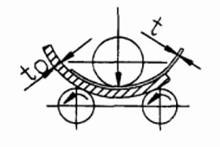
Flat Parts Rolling:
Roll the flat parts separately back and forth before performing roundness correction.
The press distance should be 3-5mm each time until the roundness matches the sample, using a visual inspection method.
Rolling the Welding Joint:
Position the cylinder welding joint at the bottom.
Adjust the upper roller downward to make contact with the cylinder.
Slowly lower the upper roller and roll back and forth with initial lower pressure, generally not exceeding 15mm.
For subsequent rolls, the cylinder should not exceed 10mm per roll.
(Refer to the press distance of the cylinder for one cycle rolling = diameter * plate thickness / 10000).
Maximum Pressure and Rolling
Adjusting Maximum Pressure:
The maximum lower distance of the upper roller for circle correction (Refer to the maximum pressure of the cylinder = diameter * plate thickness / 3000) can be adjusted as needed but should not exceed 20% of the reference value.
Even Stress Distribution:
When the lower distance reaches the optimal condition, roll five more circles to ensure even stress distribution.
Measure the inner circle roundness at a point lower than the horizontal diameter.
Final Adjustments and Measurements
Final Rolling and Measurement:
Lower the amount in place after rolling around five laps to ensure even stress distribution.
Measure the cylinder diameter circle by lowering the level (clockwise 7-8 or 4-5 for the hour pointer).
Lifting the Upper Roller:
If the cylinder’s roundness is consistent after measurement, slowly raise the upper roller, increasing the distance by no more than 5mm per turn, generally 2-3mm.
After 3-4 turns, the upper roller should no longer contact the cylinder.
Roundness Verification:
Measure the roundness with a tape measure. Generally, a roundness deviation of less than 10mm is acceptable.
Additional manual circle correction may be necessary to meet drawing specifications.
Artificial Roundness Correction
Flame Heating Method:
Typically, the flame heating method is used for roundness correction.
Mark the maximum and minimum sizes and arc positions using a sample or tape measure. Ensure the marks are precise and visible.
Heating for Correction:
Heat the unqualified circular arc and size positions with a flame.
For thick plates, use a large electrical flame for heating.
Heat to around 600-700℃ for low carbon steel Q235, using point or linear heating to create a temperature difference in the steel plate’s thickness direction. This induces local deformation to achieve the desired roundness correction.
Post-Heating Measurement:
After cooling, measure the heated position using a sample and tape measure.
If the measurement is not within specified tolerances, employ an artificial circular correction method to align with drawing requirements.
As the founder of MachineMFG, I have dedicated over a decade of my career to the metalworking industry. My extensive experience has allowed me to become an expert in the fields of sheet metal fabrication, machining, mechanical engineering, and machine tools for metals. I am constantly thinking, reading, and writing about these subjects, constantly striving to stay at the forefront of my field. Let my knowledge and expertise be an asset to your business.
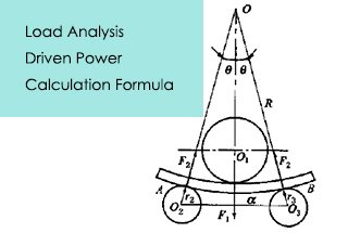
Have you ever wondered how a massive steel plate is bent into shape? In this article, we explore the fascinating mechanics behind plate rolling machines, revealing the forces and calculations…
Ever wondered who the top players in plate rolling machines are? This article introduces the leading manufacturers in the industry, detailing their innovations, product ranges, and global reach. From established…
Have you ever wondered how massive steel structures are shaped into perfect cylinders and cones? This article explores the fascinating world of plate rolling machines, essential tools in industries like…
Have you ever wondered how massive metal structures like wind turbines and ships get their precise shapes? This article unveils the fascinating world of metal plate rolling machines, showcasing their…
Imagine trying to bend a thick steel plate into a perfect cylinder—how much force would you need? This article dives into the critical calculations for determining the load and power…
Have you ever wondered how those massive steel structures are formed into perfect curves? Roll bending is the secret behind it. In this article, we'll dive into the fascinating world…
Imagine transforming flat metal plates into precise cylinders or intricate shapes with just one machine. Welcome to the world of the plate roll bending machine! This powerful tool, essential in…
Ever wondered how massive metal sheets are seamlessly bent into precise shapes? The four-roller plate bending machine is the powerhouse behind this transformation. This guide dives into its structure, technical…
Have you ever wondered how massive steel plates are transformed into perfectly curved shapes? In this captivating blog post, we'll dive into the fascinating world of 3-roll bending machines. Discover…