Common Types of Level Gauges
- Magnetic Flip Level Gauge
- Float Ball Level Gauge
- Steel Tape Level Gauge
- Radar Level Gauge
- Magnetostrictive Level Gauge
- RF Admittance Level Gauge
- Tuning Fork Level Gauge
- Glass Plate/Glass Tube Level Gauge
- Hydrostatic Level Gauge
- Pressure Level Transmitter
- Capacitive Level Gauge
- Smart Electric Float Level Gauge
- Buoyancy Level Gauge
- Float Level Transmitter
- Electrical Contact Level Gauge
- Magnetic Bicolor Electronic Level Gauge
- External Measurement Level Gauge
- Hydrostatic Level Gauge
- Ultrasonic Level Gauge
- Differential Pressure Level Gauge (Double Flange Level Gauge)
Working Principles of Common Level Gauges
1. Magnetic Flip Plate Level Gauge
Also known as a magnetic float level gauge or magnetic flip column level gauge.
This gauge operates on the principle of a communicating vessel, developed based on the principles of buoyancy and magnetic coupling.
As the liquid level in the container being measured rises or falls, the permanent magnet steel inside the float transmits to the magnetic flip column indicator panel via magnetic coupling, causing the red and white flip column to rotate 180°.
When the liquid level rises, the column flips from white to red, and when the liquid level falls, it flips from red to white. The intersection of red and white on the panel indicates the actual height of the liquid level in the container, thereby displaying the liquid level.
2. Float Level Gauge
The Float Level Gauge primarily operates based on buoyancy and the principles of static magnetic fields.
The location of the float containing a magnet (hereafter referred to as the float) within the medium being measured is influenced by buoyancy: changes in liquid level lead to alterations in the position of the magnetic float.
The magnet within the float interacts with a sensor (magnetic reed switch), causing the number of components (such as fixed resistors) connected in the circuit to vary, subsequently altering the electrical quantities within the instrumentation circuit system.
Essentially, changes in the position of the magnetic float trigger variations in electrical quantities. The state of the liquid level within the container is reflected by detecting these electrical quantity changes.
3. Tape Level Gauge
The Tape Level Gauge is designed and manufactured based on the principle of mechanical balance.
When the liquid level changes, the original mechanical balance is disturbed by the buoyancy affecting the float, achieving a new equilibrium through the movement of the steel tape.
The liquid level detection device (float), based on the liquid level’s state, triggers the steel tape to move. This displacement drives the rotation of the transmission shaft through the motion of the steel tape, which in turn acts upon the counter to display the liquid level.
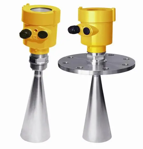
4. Radar Level Meter
The radar level meter is a measurement instrument based on the principle of time of flight. Radar waves travel at the speed of light, and their travel time can be converted into a level signal by electronic components.
The probe emits high-frequency pulses that propagate along a cable-style probe.
When these pulses encounter the surface of the material, they are reflected back and received by the receiver within the instrument, which then converts the distance signal into a level signal.
5. Magnetostrictive Level Gauge
During the operation of the magnetostrictive level gauge’s sensor, the circuitry within the sensor induces a pulse current on the waveguide wire.
This current, while propagating along the wire, generates a pulse current magnetic field around it.
The sensor probe of the level gauge is fitted with a float, which moves up and down with changes in the liquid level along the probe. Inside the float is a set of permanent magnetic rings.
When the magnetic field of the pulse current encounters the magnetic field from the magnetic rings of the float, the magnetic field around the float alters, causing a torsional wave pulse at the float’s position on the waveguide wire made of magnetostrictive material.
This pulse is transmitted back along the waveguide wire at a fixed speed and detected by the detection mechanism. By measuring the time difference between the pulse current and the torsional wave, the precise location of the float, and thus the position of the liquid level, can be accurately determined.
6. Radio Frequency Admittance Level Meter
The Radio Frequency Admittance Level Meter consists of a sensor and a control instrument.
The sensor, which can be rod-type, coaxial, or cable-probe, is installed at the top of the bin. The pulse card within the sensor converts level changes into pulse signals sent to the control instrument.
The control instrument, after computational processing, converts these signals into displayed engineering units, thereby accomplishing continuous level measurement.
7. Tuning Fork Level Meter
The operating principle of the tuning fork level controller involves a pair of piezoelectric crystals mounted on the tuning fork base, causing the tuning fork to vibrate at a certain resonant frequency.
When the tuning fork comes into contact with the medium being measured, its frequency and amplitude change.
These modifications are detected and processed by an intelligent circuit, which then converts them into a switch signal.
8. Glass Plate Level Gauge (Glass Tube Level Gauge)
The Glass Plate Level Gauge is a device that establishes a connection with the vessel via a flange, allowing for the immediate reading of the liquid level height within the vessel through the glass plate.
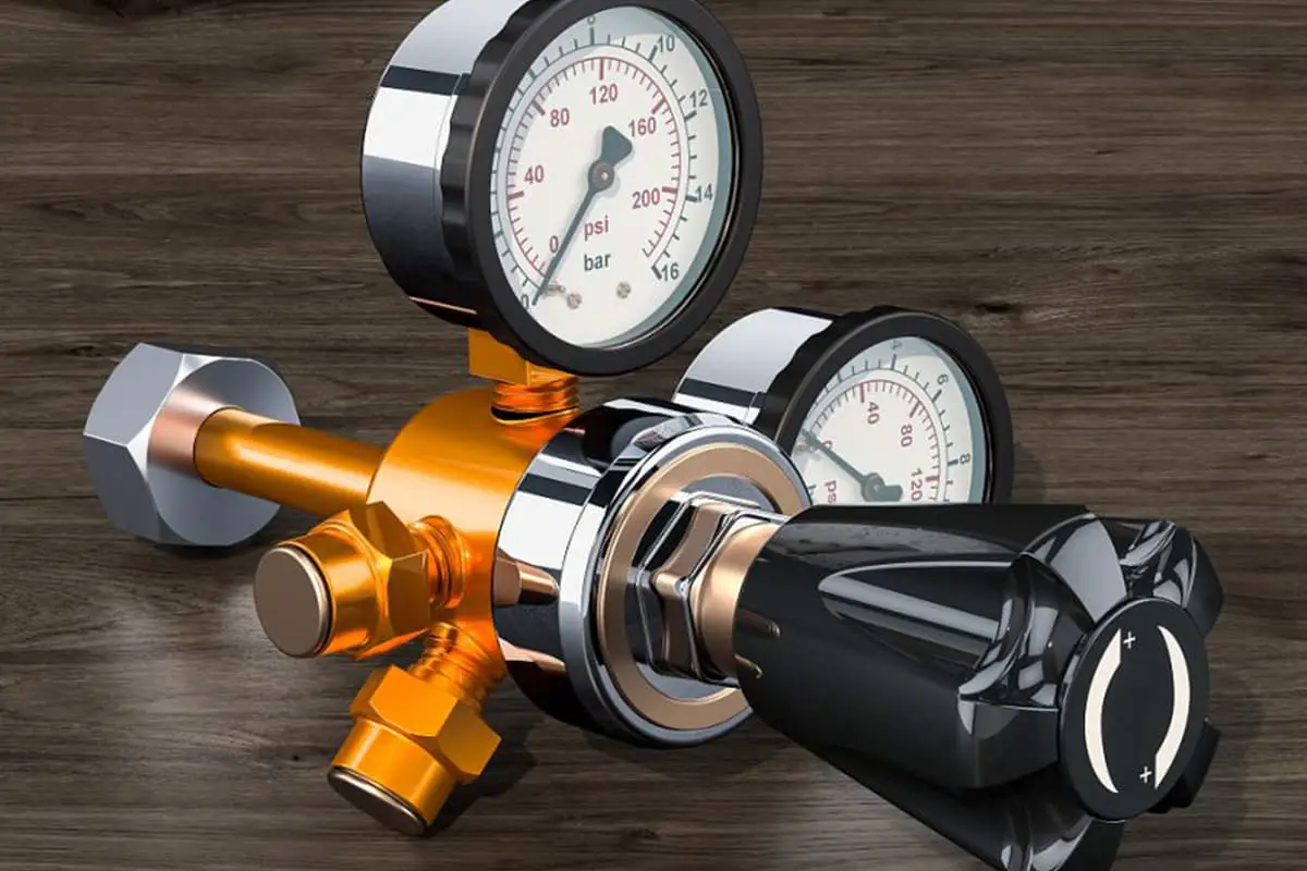
9. Pressure Level Transmitter
The pressure-style level gauge employs the principle of static pressure measurement.
As the level transmitter is immersed into a specific depth of the liquid under inspection, the sensor faces the pressure exerted by the fluid. This pressure is then introduced into the positive-pressure chamber of the sensor via a gas-guiding stainless steel.
Concurrently, the atmospheric pressure Po above the fluid surface is connected with the sensor’s negative pressure chamber to offset the Po at the back of the sensor. This allows the sensor to measure the pressure as: ρ.g.H. By measuring the pressure P, the depth of the fluid can be determined.
10. Capacitive Liquid Level Gauge
The Capacitive Liquid Level Gauge measures the height of liquid surfaces by detecting changes in capacitance. It incorporates a metal rod inserted into a liquid-filled vessel, where the rod functions as one pole of the capacitor and the vessel wall as the other.
The dielectric between the two poles consists of the liquid and the gas above it. Given the differing dielectric constants ε1 for the liquid and ε2 for the gas above (where ε1 > ε2), the overall dielectric constant—and therefore the capacitance—increases as the liquid level rises.
Conversely, when the liquid level drops, both the dielectric constant and the capacitance decrease.
Thus, the Capacitive Liquid Level Gauge can measure the height of liquid levels by observing changes in the capacitance between its two poles.
11. Intelligent Electric Float Level Gauge
The Intelligent Electric Float Level Gauge is a liquid level measuring instrument designed based on Archimedes’ principle and the principle of magnetic coupling.
The instrument can be used to measure liquid levels, interface levels, and densities while being responsible for outputting upper and lower limit alarm signals.
12. Float Level Gauge
This is designed and manufactured using the principle of mechanical balance. When the liquid level changes, the original mechanical balance is disrupted by the buoyancy acting on the float, achieving a new balance through the movement of the steel tape (rope).
The liquid level detection device (float) moves the steel tape (rope) according to the liquid level status, and the displacement transmission system drives the on-site indicator through the movement of the steel tape (rope), thereby displaying the liquid level status on the display device.
13. Float Level Transmitter
The float is submerged in the fluid within the float chamber, rigidly connected to the torque tube system. The force endured by the torque tube system is the net value of the float’s weight minus the buoyancy it receives. Under this combined force, the torque tube rotates a certain degree.
Variations in the position, density, or level of the liquid within the float chamber cause changes in the buoyancy experienced by the submerged float, hence altering the rotation angle of the torque tube.
This change is conveyed to the sensor rigidly connected to the torque tube, causing an output voltage variation, which is then amplified by electronic components and converted into a 4-20mA current output.
The float level transmitter uses a microcontroller and associated electronic circuits to measure process variables, provide current output, drive LCD displays, and provide HART communication capabilities.
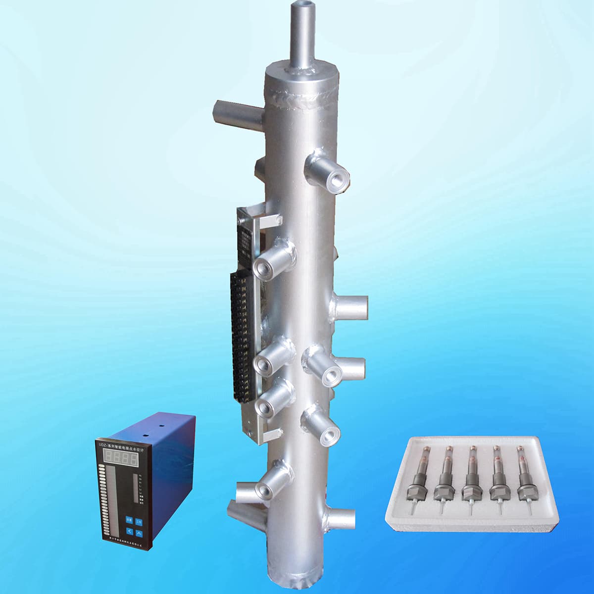
14. Electric Contact Level Gauge
The Electric Contact Level Gauge is designed based on the differing resistivity of water and steam.
The impedance from the electrode to the body of the measuring tube is lower in water and higher in steam.
As the water level changes, the number of electrodes in the water varies, resulting in a change in resistance value.
This information is transmitted to the secondary instrument, thus enabling functions such as water level display, alarms, and protective interlocks.
15. Magnetic Bicolor Electronic Liquid Level Gauge
The Magnetic Bicolor Electronic Liquid Level Gauge is manufactured using high-quality stainless steel and imported electronic components.
The display section utilizes high-brightness LED bicolor light-emitting diodes to form a columnar display screen.
Through the red and green changes of the LED light column, it can achieve upper and lower limit alarms and control for liquid levels.
16. External Level Gauge
The external level gauge is an instrument that utilizes the principles of sonar ranging and “micro-vibration analysis” technology to measure the liquid level from outside the container.
Two compact ultrasound sensors of the external level gauge are installed, one at the bottom of the tank and the other at the side wall for density variation compensation.
The signal from the external level gauge sensor is transformed by a microprocessor and output to a local display or user control system, enabling the calculation of the liquid height and volume within the tank.
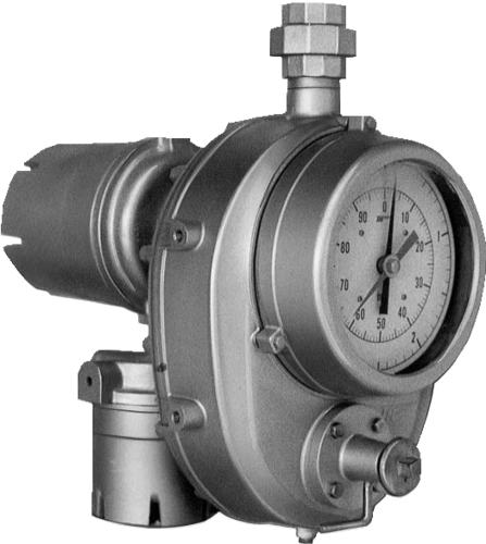
17. Hydrostatic Level Gauge
The hydrostatic level transmitter, encapsulating a diffused silicon oil-filled core within a stainless steel casing, features a protective cap at the front end to shield the sensor diaphragm, while also ensuring fluid makes smooth contact with the diaphragm.
The waterproof wiring is sealed to the exterior casing, and a ventilation tube inside the cable maintains a connection with the external environment, all within an anti-condensation designed internal structure.
18. Ultrasonic Liquid Level Gauge
The Ultrasonic Liquid Level/Position Gauge comprises a complete ultrasonic sensor and control circuitry.
The ultrasonic waves emitted by the sensor are reflected off the liquid surface, and the time taken for these waves to return is measured and used for calculations.
Adjustments are made for the influence of temperature on the ultrasonic wave transmission process via a temperature sensor, which is then converted into the distance between the liquid surface and the ultrasonic sensor.
This information is displayed on an LCD and outputs a 4mA-20mADC analog signal, enabling remote reading of the onsite instrument.
19. Differential Pressure Liquid Level Gauge (Double Flange Level Gauge)
A differential pressure liquid level transmitter operates by measuring the difference in pressure between two points and then converting this data into an electrical signal that is relayed to electrical components in the control room.
This type of gauge is primarily used for measuring liquid levels in sealed pressure vessels. The magnitude of the differential pressure corresponds to the height of the liquid level.
The level is determined by measuring the differential pressure between the gas and liquid phases using a differential pressure gauge.