Explore 4 Different Types of Power Transmission Systems
Have you ever wondered how power is transmitted in various machines and devices? From the engines that propel our vehicles to the motors that drive our industries, power transmission is…
Ever wondered why transmission shafts are typically circular? This article dives into the mechanical reasons behind the shape, explaining how a circular cross-section optimizes torsional performance and minimizes stress. You’ll learn about the advantages of this design in resisting deformation and ensuring efficient power transmission. By the end, you’ll understand why the circular design is crucial for maintaining mechanical integrity under varying loads. Read on to uncover the engineering principles that make the circular transmission shaft a preferred choice in mechanical systems.
(1) Convention on torque symbols
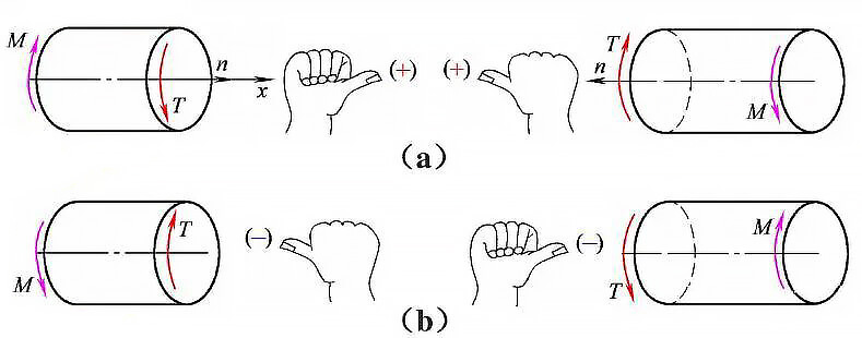
Fig. 1 direction and symbol of torque
(2) Torsional deformation of circular section bar
After twisting a shaft with a circular cross-section, the shape and size of the section remain the same and it stays flat. The radius of the section remains as the axis around which the section is twisted, and each section only rotates by a small angle γ relative to each other.
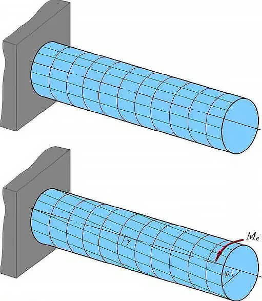
Fig. 2 torsional deformation of circular section bar
(3) Torsion of non-circular section bar
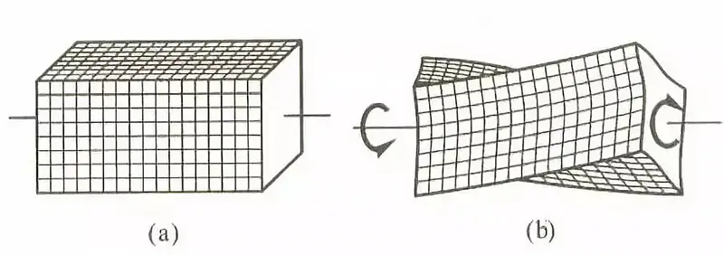
Fig. 3 torsional deformation of square bar
Free torsion:
When a bar has a non-circular cross-section, it will warp during torsion deformation. The degree of warpage of adjacent cross-sections will be the same, meaning that the length of all longitudinal fibers in the bar will not change. In this scenario, there will be no normal stress on the cross-section, only shear stress.
To achieve free torsion, the two ends of the straight bar must be subjected to external torque, and the warpage of adjacent sections should not be constrained externally.
Constrained torsion:
When a non-uniform straight bar is twisted, the amount of torque applied changes along the length of the bar. If one end of the bar is fixed and cannot move, the degree of warping of adjacent sections of the bar will be different. In addition to shear stress, there will also be normal stress on the cross-section of the bar.
Normally, the normal stress caused by restrained torsion in a solid bar is small and can be neglected. However, for thin-walled bars, this normal stress is often too large to be ignored.
(1) Plane hypothesis
After twisting, the circular section remains flat, and its shape, size, and radius remain unchanged. The sections rotate relative to each other by only a small angle γ. However, this assumption only applies to the axis of the circular section and not to the axis of non-circular sections.
The spacing between adjacent sections remains the same, except for when τzx = τzy, which indicates no normal stress.
σ x= σ y= σ z= τ xy=0.
The elasticity model is shown in Fig. 4.

Fig. 4 torsion elastic mechanical model of straight bar
(2) Membrane analogy
Prandtl pointed out that the sag of a thin liquid film, also known as a membrane, under uniform pressure is mathematically similar to the stress function in the torsion problem of a straight bar with an equal cross-section.
Comparing the torsion bar with the membrane can be helpful in solving the torsion problem.
In Figure 5, there is a uniform film stretched on a horizontal boundary, which has the same shape and size as the cross-sectional boundary of a torsion bar.
When a small uniform pressure is applied to the film, each point of the film will experience a small sag.
If the plane where the boundary is located is the xy plane, the sag can be represented by z.
Due to the flexible nature of the film, it is assumed that it cannot withstand bending moment, torque, shear force, or pressure. It only bears a uniform tensile force FT, which is similar to the surface tension of liquid film.
According to this analysis, the shear stress at any point on the cross-section of the torsion bar, along any direction, is equal to the slope of the film in the vertical direction at that point.
It can be observed that the maximum shear stress on the cross-section of the torsion bar is equal to the maximum slope of the membrane. However, it should be noted that the direction of the maximum shear stress is perpendicular to the direction of the maximum slope.
By making this assumption, it is possible to determine the maximum shear stress and relative torsion angle of the non-circular section straight bar listed in Table 1 below.

Fig. 5 Membrane analogy model
(1) Solid circular shaft
Under assumptions 1 and 2, the mechanical properties of plastic materials in pure shear when the component materials are within the elastic range:
τ= G γ,γ Is the shear strain;
γ=φ R/L( γ is the relative torsion angle of two sections at a distance of L;
φ is the corner of the end face of the torsion end, R is the outer radius of the circle, and L is the spacing between two sections).

Fig. 6 schematic diagram of torsion of bar with solid circular section
The shear stress at ρ on the circular section is:

Under the same torque condition, the shear stress (τ) on a circular cross-section bar is proportional to the distance from the center of the section (ρ). This means that the larger the distance from the center, the higher the shear stress.
When the distance from the center is equal to the radius (R) of the circular section, the maximum shear stress is obtained at the edge.
The torsional section modulus (Wp) of a circular shaft can be expressed as IP/R, where IP is the polar moment of inertia. This value is only related to the geometric dimensions of the section and not to the cross-sectional area.
The maximum shear stress (τ max) can be calculated as T/WP, where T is the applied torque.
For a solid shaft with a circular section, the torsional section modulus (WP) is approximately equal to 0.2 times the cube of the diameter (D).
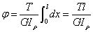
The torsion angle (φ) of a round bar under torsion is related to the torsional stiffness (GIP) of the circular section, which reflects the ability of the shaft to resist deformation.
The relative torsional angles of two sections at a distance of L can be calculated using a torsion formula.
Relative angle of twist:
Stiffness condition of circular shaft:

(2) Hollow circular shaft
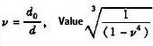
The section torsional coefficient of hollow circular shaft is about: WP ≈ 0.2D3 (1- α 4),0< α= d/D<1.
When α= 0.8, the WP is 60% of the solid circular section, that is, under the same torque, the strength decreases by 40%, but under the same material and length, the weight difference is 2.8 times.
(3) Closed thin-walled tube
A round pipe with a wall thickness (a) much smaller than its radius (R0) – typically considered ≤ R0/10 – is known as a thin-walled round pipe. This type of pipe can be of any shape and equal section.
As a thin-walled pipe, it is assumed that the shear stress is uniformly distributed throughout the entire wall thickness (t) to obtain an approximate solution.
Applying the reciprocal shear stress rule, it can be concluded that the product of the average axial shear stress of all points on the pipe section and the pipe wall is equal, i.e., the shear flow (q) is constant.
Since the value of q is consistent throughout the entire section, the maximum shear stress is at the minimum wall thickness.
When the pipe section is circular, its area (Am) equals πR0². Increasing the diameter of the cylinder can significantly reduce the shear stress.

Fig. 6 shear stress distribution of several common sections
During the torsion test, the stress distribution across the cross-section of the specimen is uneven. The surface experiences the largest amount of stress, and as we move towards the center, the stress reduces.
As a result, when the material is twisted, the damage begins from the outermost layer of the round rod and progresses towards the inside. The crack initiates from the surface layer and propagates inwards.
In engineering, the torsion test is commonly utilized to examine the surface defects and the performance of surface hardening layers in materials.
As shown in Fig. 7.

Fig. 7 torsion test of round bar sample
In the torsion process of a circular shaft made of plastic materials such as low-carbon steel, the surface of the shaft will yield first, and then the circumference will be cut off along the section as torsional deformation increases.
This is due to the fact that the material’s shear capacity is lower than its tensile capacity, and the maximum shear stress occurs on the cross-section, resulting in shear failure.
In engineering, the maximum shear stress on the outer edge of the cross-section is usually set to the shear yield limit of the material (τs) as the dangerous state, and the strength condition is established based on this.
However, even when the shear stress on the edge reaches the yield limit, other parts are still in the linear elastic working state, and the round rod will not undergo obvious plastic deformation, allowing the torque to continue to increase.
Taking material plasticity into consideration, the ultimate torque (plastic torque) of a solid round rod is 1/3 larger than the yield torque (which is the result of simplified engineering calculation).
When the shear stress at the edge of the material cross-section reaches the shear yield limit of the material τs, the plastic region gradually expands inward with the increase of the torsional couple moment, and the material at the edge of the cross-section begins to strengthen.
If the torsional couple moment continues to increase, the crack will start from the outermost layer of the round rod and eventually shear along the cross-section.
As shown in Fig. 8.

Fig. 8 torsion test of round bar sample of plastic material
In the case of a round shaft made of brittle materials, such as cast iron, with a lower tensile capacity than shear capacity, deformation during torsional failure is minimal. The shaft tends to break on the helical surface at an angle of approximately 45° to the axis.
This is because the inclined plane at 135° to the axis experiences the maximum tensile stress. If the maximum tensile stress on this section exceeds the material’s tensile strength limit, then the shaft will fail due to tension on this section.
As shown in Fig. 9.

Fig. 9 torsional test of brittle material round bar sample
The internal torque T received by the log rod not only generates a radial linear distribution of shear stress on the cross-section but also induces a corresponding shear stress along the axial plane, which can lead to cracking along the axial plane.
As wood is an anisotropic material, the shear force parallel to the fibers along the axial direction is much smaller than the shear force perpendicular to the fibers in the cross-section, resulting in the cracking pattern depicted in Figure 10.

Fig. 10 torsional failure of log
The figure illustrates the calculation formulas for maximum stress and torsion angle of square, triangular, and elliptical sections, as per the analysis of elasticity theory.
In all the aforementioned cases, the maximum shear stress occurs at the section boundary line closest to the central axis.
For a closed thin-walled pipe, the position with the thinnest wall thickness in relation to the central axis experiences the highest shear stress.

Fig. 11 calculation formula of torsional shear stress and relative torsional angle of different sections
Let S be the area of a circle, square, triangle, and ellipse, all of which are subjected to the same torque T.
The side length of a square is a = √S, while the side length of an equilateral triangle is approximately a ≈ 2.3√S.
Using the maximum stress calculation formula provided in the figure, when subjected to the same cross-sectional area and torque, the maximum shear stress on the cross-section of an equilateral triangle is about 1.8 times that of a square.
For an ellipse with a = b, making it a circle, a = 0.56√S, and the maximum shear stress on a square is about 1.32 times that of a circle.
If the ellipse has a ≠ b, with 1 > b/a = λ > 0, then the ratio of the maximum shear stress on the ellipse to the maximum shear stress on the circle is λ√S-2. Thus, the smaller the value of λ, the greater the shear stress.
Through the above comparison, it can be concluded that:
When a shaft has the same section and bears the same torque, the maximum shear stress on the circular section is the smallest compared to a non-circular section. Moreover, the torsion angle is also smaller. Thus, a circular transmission shaft has a natural advantage in torsional mechanical performance.
Extending these findings to arbitrary cross-sections, it can be proved that the circular cross-section shaft has the highest efficiency.
Table 1 torque check formula of shaft diameter
|
Axle type |
formula |
instruction |
|
solid shaft |
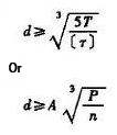 |
Where: d – calculate the diameter of the shaft at the section (mm) T-rated torque transmitted by shaft (N·mm) T=9550000P/n P-rated power transmitted by shaft (kW) n-shaft speed (R / min) [T] – allowable shear stress of shaft (MPa) A – coefficient determined by [t], V-ratio of inner diameter d0 to outer diameter D of the hollow circular shaft |
|
hollow axle |
 |
The surface shear stress of a circular cross-section shaft is high, and the center is relatively small when it bears torsional load. Therefore, removing some of the material that does not play a full role in the center can effectively reduce the weight of the shaft and improve its bending resistance.
However, deciding whether to make shaft parts hollow or not requires considering not only mechanical factors but also technological and manufacturing costs. It’s important to note that the wall thickness should not be too thin, or local folds may occur, leading to a loss of bearing capacity.
When the wall thickness (δ) of the cylinder is much smaller than the radius (R0), which is generally considered to be ≤ R0/10, it’s called a thin-walled cylinder. However, if the thin-walled tube has a longitudinal opening along the axis, its torsional resistance will significantly decrease. Therefore, a diaphragm is usually added to improve its torsional stiffness and strength.
A shaft is typically composed of various sections, and stress concentration at the transition position between these sections is a common cause of failure in shaft parts.
Literature can be referred to for guidance on how to select and determine the large diameter of two adjacent sections and the transition fillet.
The cylindrical coil spring is a common component in mechanical engineering, characterized by its spiral axis and large elastic deformation.
In the design of a spring with a high load capacity, strength is typically the primary consideration. However, for a spring with a low load capacity, deformation is generally the main factor to be considered.
For less critical springs, selection can be based solely on structural dimensions and specifications.
For information on design and calculation methods for springs, please refer to relevant literature, as well as GB/T1239 series standards, GB/T2089, DIN2089, and other applicable standards.
Under the action of static load, there is a certain relationship between the mechanical properties of materials in torsion and tensile, so [σ] of materials is used to determine the allowable shear stress[ τ]:
| Material type | [σ] | [ τ] | [ τ] |
| plastic material | 1 | 0.5~0.7 [σ] | 0.55 or 0.577 [σ] |
| Brittle material | 1 | 0.7~1.0 [σ] | 0.8~1.0 [σ] |
The table above highlights that the relationship between shear stress and normal stress provided in the literature differs.
Several plastic materials mentioned in the literature show that the ratio of shear stress to normal stress should be between 0.5 to 0.7 [σ].
However, this relationship is a rough estimate and should only be used when the exact shear stress data is not available.
For precise verification, obtaining the specific torsional strength value of the material is necessary.

As the founder of MachineMFG, I have dedicated over a decade of my career to the metalworking industry. My extensive experience has allowed me to become an expert in the fields of sheet metal fabrication, machining, mechanical engineering, and machine tools for metals. I am constantly thinking, reading, and writing about these subjects, constantly striving to stay at the forefront of my field. Let my knowledge and expertise be an asset to your business.