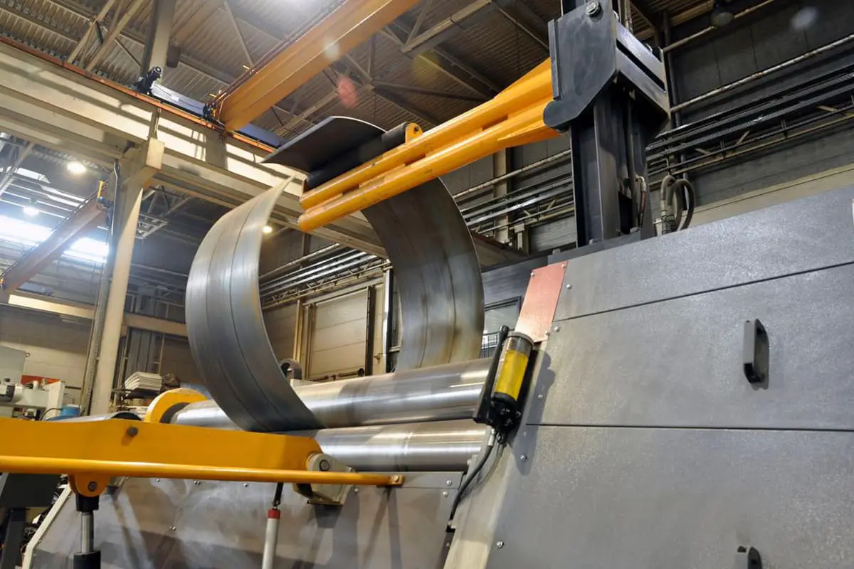
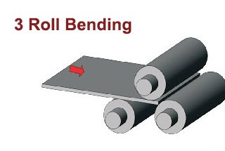
In the manufacturing of boilers and pressure vessels, forming technology is one of the primary manufacturing processes.
In the forming process, the rolling of the cylinder section is the most basic forming method. There is a lot of work involved in rolling. Most of the forming process is carried out on a symmetrical three-roll bending machine. However, due to the thickness and diameter of the cylinder section being determined according to different production process conditions, there are a considerable number of specifications and varieties.
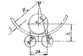
The accuracy of the curvature after forming depends on the parameter “H,” which is the center distance between the upper and lower rollers at the end of the rolling.
This parameter is usually determined by the formula (1).
It may seem that this formula is not complicated, but for manufacturers, the cumulative workload is considerable due to the various specifications and varieties of cylinder sections.
In order to simplify and facilitate the determination of the value of “H” under different conditions, this article will use the following two graphical algorithms.
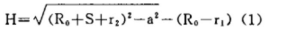
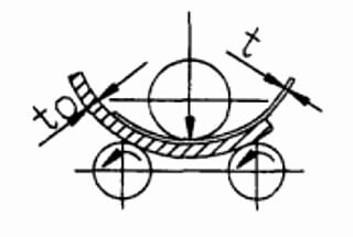
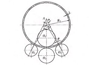
Fig. 1 The end position diagram of symmetrical three roller plate bending machine
1. A graph algorithm to calculate the “H” parameter by “nomograph of calculating the square root of the sum of squares”
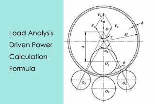
When a certain type of plate rolling machine is given, the parameters a, r1 and r2 in the above formula are constants, only s and R0 are variables.
Therefore, when a certain type of plate bending machine is used to roll any thickness and radius of curvature, the corresponding main parameter “h” can be obtained by the following graph algorithm.
Firstly, a rectangular coordinate system is established with a as ordinate and h as abscissa.
Then the following drawing is carried out in the coordinate system (shown in Fig. 2)
It should intercept OP = a on the longitudinal axis, take point P as the center of the circle, and take (R0 + S + r2) as the radius to make a positive point a on the transverse axis of the arc intersection.
It should take point a as the center of the circle, take R0 as the radius, and reverse as a point B on the transverse axis of the arc.
Then point B is taken as the center of the circle and R1 is taken as the radius of the arc intersection, and a point C in the positive direction of the transverse axis of the arc is made.
Thus: OC = h.
For example,
The drum sections with S = 20 mm and d = 2 000 mm are rolled on a 70 × 4000 symmetrical three roll plate bending machine.
To calculate the value of h.
According to the data, R1 = 350mm, R2 = 330mm, 2a = 800mm.
According to the graph algorithm (shown in Fig. 2): h = 640mm, which is calculated by the formula:
The absolute error is only 1 mm, accounting for 0.015% of the true value, which is enough accurate.
If (R + S + r) is made into a moving ruler, it is more convenient.
Fig. 2 Normogram to calculate “h”
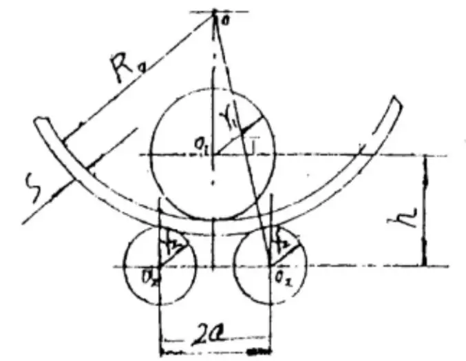
2. A graph algorithm for calculating “h” of a certain type of symmetric three roller plate bending machine, which can roll the common point graph under different thicknesses and curvature radii;
As known above, when a certain type of bending machine is given, its parameters a, R1 and R2 are fixed.
Then, if the relationship curve of R0 and h under different plate thickness is drawn in r0-h coordinate system, the common point graph of R0 and h of steel plate with different thicknesses on this type of rolling machine can be obtained.
It is very convenient to get the value of the main parameter “h” of the drum section on this type of plate bending machine under all different conditions.
The following is a common point diagram of a 70 × 4000 symmetrical three roller plate bending machine.
Known: r1 = 350mm, r2 = 330mm, a = 400mm
So:
Table 1 is the data table of calculation and drawing with s interval of 2mm.
According to practical experience, the thickness of the rolling machine is generally 6 ≤ s ≤ 40 (mm).
Generally, the radius of the rolling drum section is 400 ≤ R0 ≤ 200 (mm).
Therefore, this range is used as the calculation drawing range.
It can be seen from table 1 that the value of “n” is basically equivalent to the plate thickness s when a certain type of plate bending machine is used to roll a certain amount of R0.
The error between the actual value and the actual value is less than 0.05%.
However, when the copper plate is bent, there are both plastic deformation and elastic deformation.
Therefore, there will be a certain elastic recovery after unloading.
Therefore, in actual production, the value should be slightly less than the actual value.
In this way, if we use the law of equivalent change of the two, the drawing will be simplified and the elastic springback after actual bending can be compensated.
At the same time, the graph line can be reduced, and the “h” value corresponding to any S can be determined under a certain R0.
Conclusion
The former graph algorithm is universal, while the latter is for a certain type of plate bending machine, which type of plate bending machine corresponds to a special (k-R0-S) copoint graph.
The results of the two graph algorithms in teaching are very good and enlighten students greatly.
In particular, the latter method has certain practicability.
It is suggested that the manufacturer of plate bending machine should configure the common principal diagram of (n-R0-S) on the rolling machine or in the manual, which will bring great convenience to the actual production of the manufacturer.