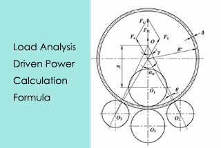
How to Calculate Motor Power for Plate Rolling Machines
Have you ever wondered how a massive steel plate is bent into shape? In this article, we explore the fascinating mechanics behind plate rolling machines, revealing the forces and calculations that make this complex process possible. Prepare to uncover the secrets of bending steel with precision and power!
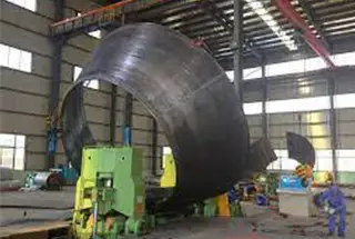
The construction and installation company of Laiwu Iron and Steel Co., Ltd. has decided to select a motor for the plate rolling machine in support of the bidding for the reconstruction and expansion of the 750 m3 blast furnace at the Laiwu Iron and Steel General Plant (Lai Steel). The plate rolling machine, which has been inactive for many years, will be utilized to prepare for the production of the blast furnace body and is capable of rolling 40mm thick steel plates.
By referring to the working principle of a multi-roll straightening machine and considering force and energy parameters, the working principle and calculation formulas of force and energy parameters for the plate rolling machine have been logically deduced.
The results of the test run indicate that the selected motor has enough driving power to meet the design capacity requirements of the plate rolling machine.
2. Bending process of steel plate on roller type plate rolling machine
The bending deformation of a steel plate on a plate rolling machine is a transverse bending process. As illustrated in Figure 1, under the influence of the bending moment M under an external load, the longitudinal fibers above the neutral layer experience compression, while the longitudinal fibers below the neutral layer undergo tensile deformation.
According to the magnitude of the external load torque, when the maximum stress on the surface layer of the steel plate is below the yield limit of the steel plate material, the longitudinal fibers in each layer are in an elastic deformation state. As the bending moment under the external load increases, the deformation of each layer of steel fibers continues.
When the external load reaches a certain point, the stress on the longitudinal fibers on the surface of the steel plate surpasses the yield limit of the material and the fibers undergo plastic deformation. The greater the load, the deeper the plastic deformation zone extends from the surface layer to the neutral layer.
When the stress on all the longitudinal fibers in the cross-section of the steel plate exceeds the yield limit of the material, all the fibers enter a plastic deformation state and the bending process is concluded.
The reverse bending ratio 1/ρ, which refers to the curvature of the steel plate after bending in one direction due to the action of the bending moment M.
The residual curvature 1/r, which refers to the curvature of the steel plate after elastic recovery under the influence of the elastic internal moment after the removal of the external load (r is the diameter of the rolled steel pipe).
The selection of the reverse bending ratio is critical in determining if the steel plate can achieve the desired bending outcome. In a three-roller plate roll, the reverse bending ratio is achieved by pressing down on the reduction roll.
Different residual curvatures can be obtained by adjusting the reduction to produce different diameters of rolled pipes.
4. Calculation of force and energy parameters of the plate rolling machine
The force and energy parameters of the plate rolling machine refer to the pressure (bending force) exerted on the roller, the bending torque, and the driving power of the motor of the plate rolling machine.
4.1 Pressure (bending force) acting on the roller of the plate bending machine
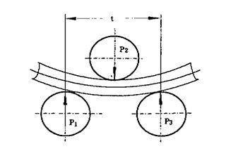
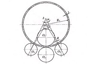
The pressure on the roller can be calculated based on the moment needed for bending the steel plate. In this case, the steel plate is considered a beam under a concentrated load. The load is the pressure exerted by each roller on the steel plate, as depicted in Figure 2.
Fig. 2 Pressure (bending force) acting on the roller
P1: Pressure of the first roller on the steel plate
P2: Pressure of the second roller on the steel plate
P3: Pressure of the third roller on the steel plate
t: Roll pitch
In the calculation, the bending moment of the steel plate under the second roll is assumed to be pure plastic bending moment Ms, that is, M2 = Ms (pure plastic bending moment M is the maximum bending moment that may be reached in elastic-plastic bending).
In the formula:
σs — yield limit of steel plate material, 250Mpa;
s — plastic section coefficient, which is bh2 / 4tb for steel plate;
In this way, P1, P2, P3 can be calculated according to the balance condition of external force on the steel plate under the second roller:
Total pressure:
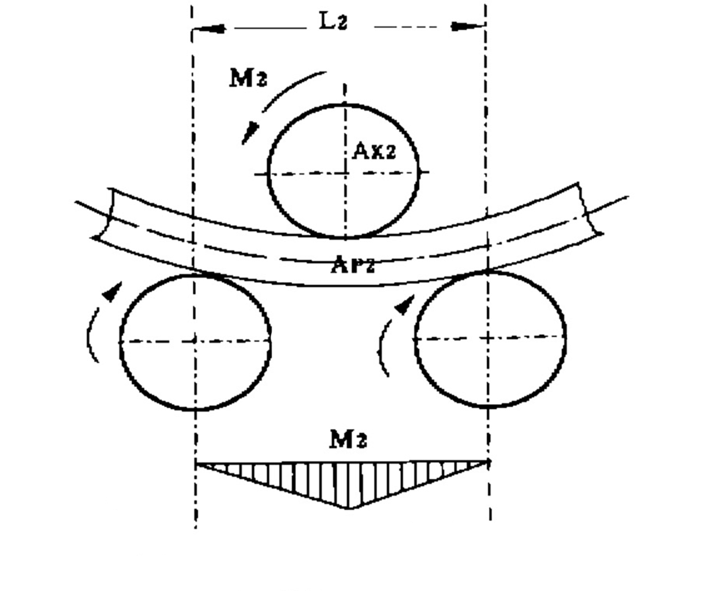
4.2 Bending torque acting on the roller of plate bending machine
The bending torque MK acting on the roller can be determined according to the principle of equal function.
The bending work AK produced by bending torque on the roller shall be equal to the work AP for plastic deformation of steel plate, i.e. Ap = Ak (shown in Fig. 3).
Fig. 3 Variation of bending moment along plate length
The plastic deformation work Ap2 of the steel plate under the second roll is:
In the formula:
M2 – bending moment of steel plate under the second roller;
1 / rp2 — plastic deformation curvature of steel plate under the second roller.
Bending work acting on the second roller:
Where D2 is the diameter of the work roll.
To make:
For the convenience of calculation, the following assumptions are made:
rp2 can be approximately equal to the diameter of the rolled tube;
The bending moment M2 of the steel plate under the second roll is equal to pure plastic bending moment Mk2.
Then the formula is as follows:
5. Calculation of motor driving power of plate rolling machine
The motor power can be calculated according to the following formula:
In the formula:
Mk — bending torque, kN.m;
P – the total pressure acting on the roller, kN;
d – rolling friction coefficient of roller and steel plate, the steel plate is 0.0008 m;
μ – friction coefficient of roller bearing, the sliding bearing is 0.05 ~ 0.07;
D – diameter of roller body, m;
v – Speed of roll body, V/S;
t – transmission efficiency, 0.65-0.80.
According to the above calculation formula, the motor driving power of 40 mm thick steel plate rolling machine is selected as follows:
It is known that: h = 40 mm, D = 420 mm, t = 900 mm, the maximum width of rolled steel plate b = 2500 mm, the minimum rolling diameter r = 1000 mm, d = 400 mm, v = 2 m/min.
Thus:
According to the above calculation, the motor driving power of the 40 mm steel plate rolling machine is selected as 25 kW.
As the founder of MachineMFG, I have dedicated over a decade of my career to the metalworking industry. My extensive experience has allowed me to become an expert in the fields of sheet metal fabrication, machining, mechanical engineering, and machine tools for metals. I am constantly thinking, reading, and writing about these subjects, constantly striving to stay at the forefront of my field. Let my knowledge and expertise be an asset to your business.
Imagine trying to bend a thick steel plate into a perfect cylinder—how much force would you need? This article dives into the critical calculations for determining the load and power…
Imagine transforming a flat sheet of metal into a complex curve with precision and efficiency. Roll bending machines, crucial in industries like shipbuilding and aerospace, achieve this through advanced technologies,…
Have you ever wondered how massive steel structures are shaped into perfect cylinders and cones? This article explores the fascinating world of plate rolling machines, essential tools in industries like…
Ever wondered how massive metal sheets transform into precise cylindrical shapes? This article unveils the fascinating mechanics behind four-roll plate bending machines, exploring their structure, working principles, and the critical…
Have you ever wondered how massive steel plates are transformed into perfectly curved shapes? In this captivating blog post, we'll dive into the fascinating world of 3-roll bending machines. Discover…
Have you ever wondered how a four-roller plate bending machine achieves such precise curves? This article explores the calculation of side roll position shifts, guided by an experienced mechanical engineer.…