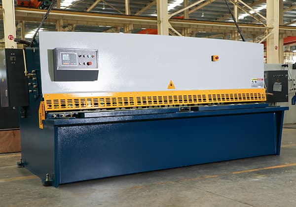
Hydraulic Shearing Machine: The Ultimate Guide
Have you ever wondered how those massive steel plates are cut with such precision? Enter the world of hydraulic shearing machines - the unsung heroes of the metal fabrication industry.…
How do you ensure precise cuts without damaging the material in hydraulic swing beam shears? This article delves into the critical factors of shear force calculation, shear angle, and shear gap adjustments in hydraulic swing beam shears. By understanding these key elements, readers will gain insights into optimizing shear quality and maintaining equipment efficiency, ultimately enhancing their metalworking operations.
Swing plate shears are widely used due to their simple structure, low failure rate, high cutting efficiency, and ability to prevent bowing, warping, and distortion of the plate after shearing, unlike ordinary plate shears. This is mainly because they mostly adopt an oblique cutting edge.
During the shearing process, the turret of the swing shear rotates, causing the angle and clearance of the blade to change. However, in the design process, the shear force calculation of the swing beam shear is often based on the shear force calculation formula of the blade support’s straight-line movement. This can lead to inaccurate calculations, deviation from the design size, and can further affect its normal performance.
The calculation of shear force in oblique-blade shearing machines that move the tool post in a straight line mostly utilizes the Nosari formula, which was proposed by scholars in the former Soviet Union.
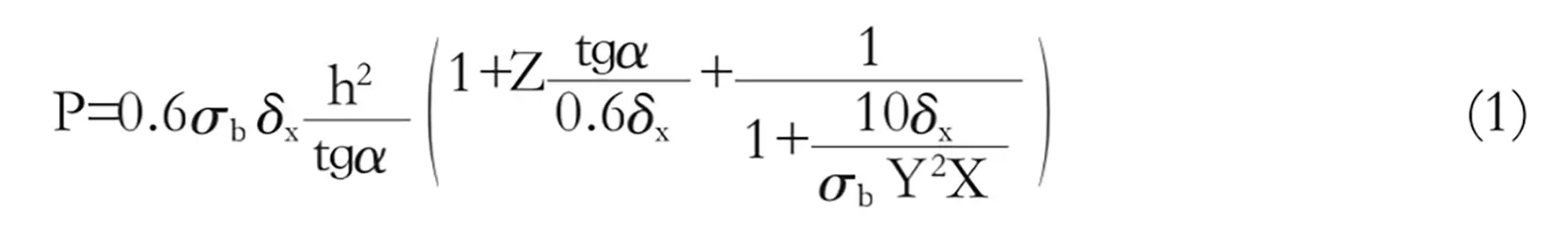
In the formula:
Clearly, formula (1) does not account for the shearing process after the shear angle changes, and the shear gap is also considered based on a one-time value. As a result, it is only suitable for the knife frame that performs linear motion shear.
In swing-type plate shears, in order to maintain a constant shear gap and shear angle during the shearing process, the blade mounting surface on the tool holder must be machined into a spiral surface in space.
However, in practice, to simplify the machining process and take into account the shape of the blade (which is generally rectangular with a flat back surface), the spiral surface is directly machined into a plane that is parallel to the axis of rotation of the tool holder.
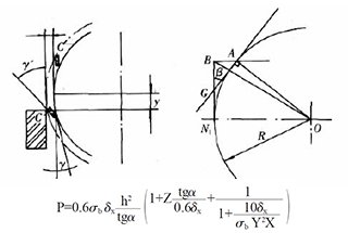
As shown in Figure 1, there is an ideal installation position at AA’ and an actual installation position at BB’ (where Ф represents the shear angle in the figure).
Since the tool is not installed according to the spiral surface, the current installation method involves making the blade tangential to the installation surface at a certain height.
This means that when the blade is mounted onto the tool holder at a certain shear angle Ф, the blade is always tangent to AA’ (as shown in Figure 1) due to the tightening of screws.
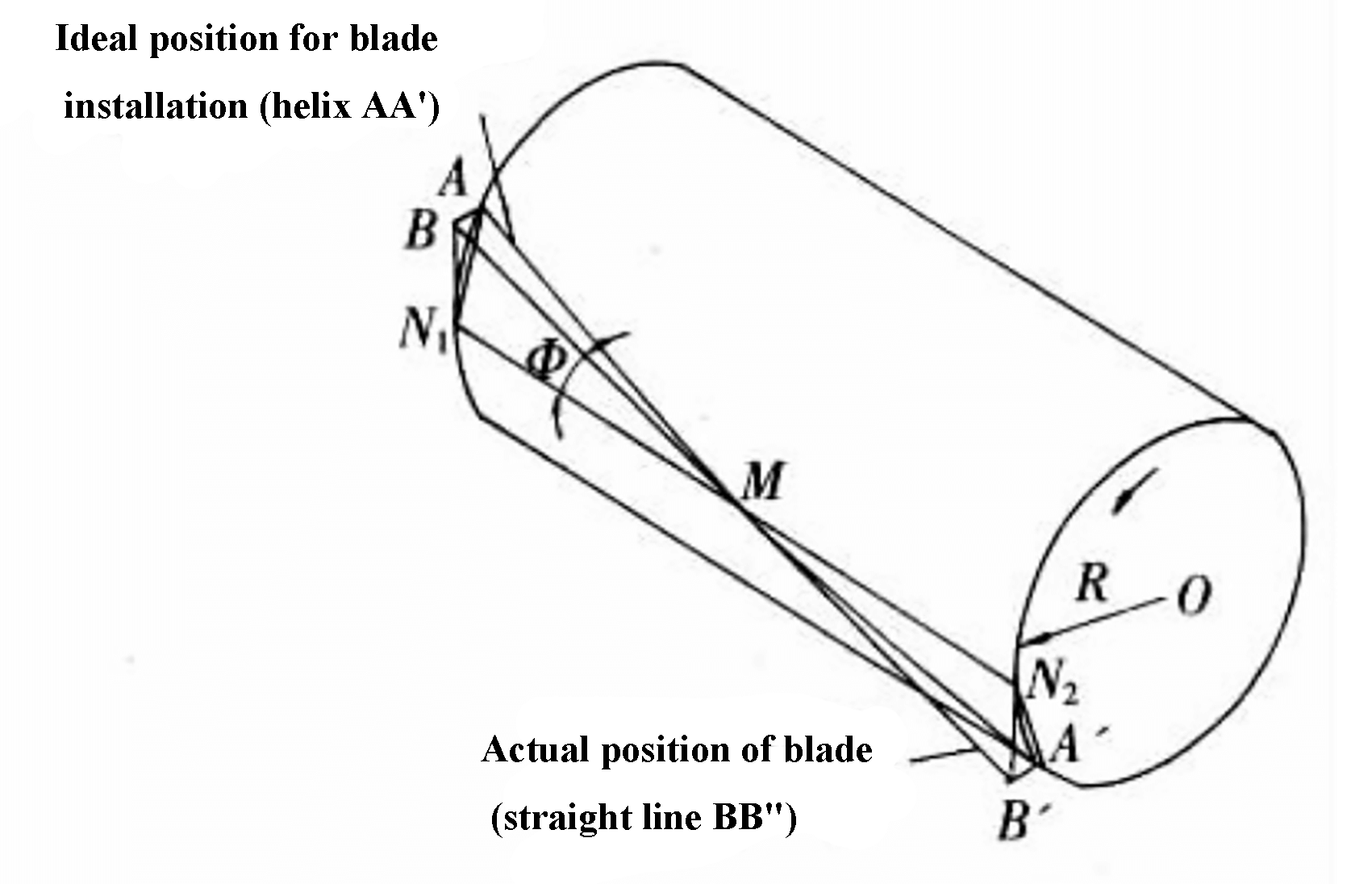
Fig. 1 Blade installation schematic in swing-type plate shears
To ensure the quality of the shear, the swing-type plate shear is raised above the y plane of the table’s rotary axis to maintain a constant clearance angle γ during the shearing process.
However, since the blade mounting plane is parallel to the rotation axis of the tool holder, a certain thickness and height of the blade can only be installed at BB’ or parallel to it.
As shown on the left side of Figure 1, the blade changes from the ideal position tangent to point A to the BN position tangent to point N. This results in a change in the shear angle as shown in Figure 2.
When the shear point is moved from point M to point B, the shear angle gradually changes from γ (which needs to be maintained at a constant value) to γ = γ’ + β.
When the shear point moves from point B to point M, γ’ = γ – β, as shown in Figure 2(a).
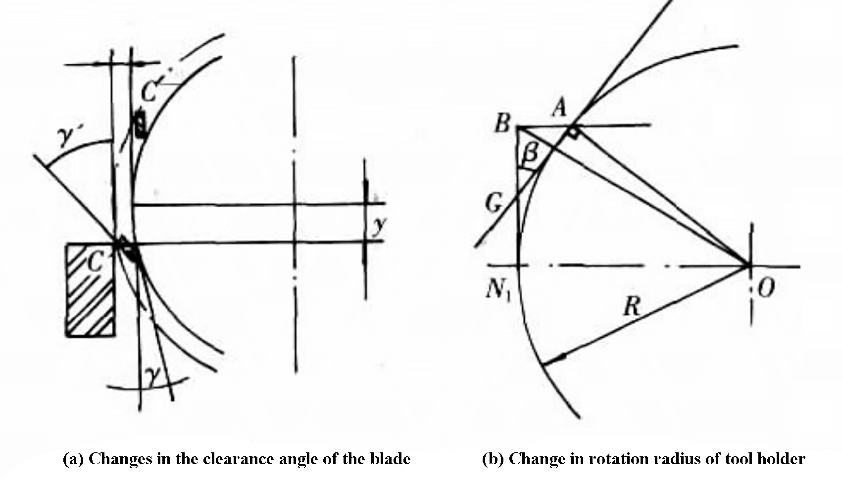
Fig. 2 Change in angle and rotation radius of the knife-edge in the swing-type plate shear processing
If the length of the shear blade is l, the shear angle is Ф, and the rotation radius of the blade is R, the geometric relationship shown in Figure 2b is obtained when the entire blade is used.

If n blades are used and the thickness is adjusted using adjustment shims, thus:

From the overall length, it can be observed that the range of the rear angle of the blade during cutting is γ ± β.
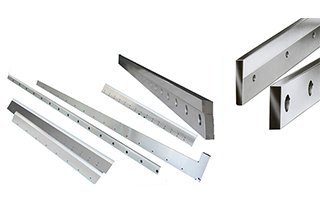
In order to facilitate installation and improve shear quality, swing-type plate shears generally use long blades.
When the blade is installed into the tool holder along the axis direction with a shear angle Ф, if the shear point moves from B’ to B (Figure 1) during the shearing process, the actual rotation radius of the tool holder will increase.
Assuming the rotation radius is R, the shear angle is Ф, and the length of the tool holder is l, the difference between the maximum rotation radius OB and R is shown in Figure 2(b):
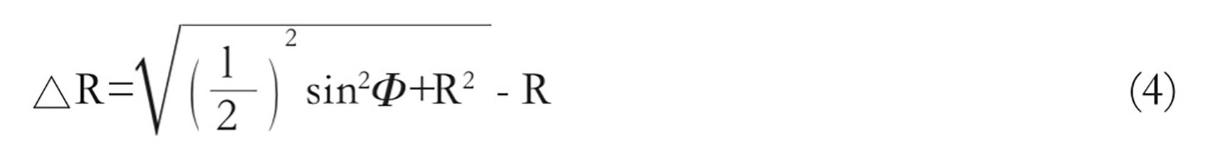
To ensure that the cutting edge does not damage the table during the shearing process, it is necessary to maintain a shear gap △ that is greater than △R.
Taking the QC12Y-6×200 swing-type plate shear as an example, with a rotation radius of R=469mm, a shear angle of Ф=1.5°, and a blade length of 1100mm with 3 pieces, substituting these values into formulas (3) and (4) gives β ≈ 5° and △R = 1.87mm, respectively.
During the plate shearing process, the quality and force of the shear are highly dependent on the shear gap. The shear and pull-off effects coexist during the process, and increasing the shear gap results in a larger proportion of pull-off, but at the same time, the shear quality worsens.
For thick plate shearing, the shear gap should generally be controlled within the range of 8% to 12% based on experience. However, the use of the simplified blade mounting surface technology of the swing-type plate shear makes it difficult to achieve this requirement.
When the shear gap exceeds the empirical value, it will inevitably lead to changes in the shear force. Equation (1) shows that an increase in the shear gap leads to an increase in the relative value of the shear blade lateral clearance, which ultimately results in an increase in the shear force required during the shearing process.
During the shearing process, the shearing action will increase the shear movement in two ways:
Firstly, it will increase the shear force, resulting in increased power loss.
Secondly, it will increase the plastic deformation of the plate, leading to increased friction between the blade and the sheared plate. This will increase the shear force required for shearing and reduce the tool life.
Therefore, for the swing-type plate shear, it is appropriate to choose a relatively larger value of the shear blade lateral clearance and blade wear coefficient when using formula (1) to calculate the shear force in order to compensate for the impact of the above factors.
To ensure the quality of shear and prevent plate friction between the blade and the back blade surface, the design of the swing-type plate shear requires that the angle between the back blade and the vertical surface of the table should be 1.5° to 2.0° during the shear process.
Based on the above analysis, the clearance angle change of the swing-type plate shear is γ ± β during the shearing process.
After calculating β ≈ 5° in the QC12Y-6×200 swing beam shear, it is difficult to ensure the design requirements of the rear angle. In the shearing process, even a negative rear angle can intensify blade wear and heat, and even produce extrusion, reducing the strength of the blade.
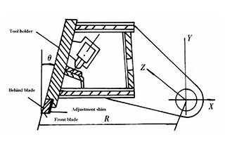
To avoid this situation, a fixed angle θ between the front of the blade and the vertical surface of the table is necessary in the tool carrier design of the swing-type plate shear (see Figure 3). As long as θ is established to be greater than or equal to -β, there will be no squeezing phenomenon between the blade and the plate. This angle is not described in some documents and is recommended to be 5° to 7°.
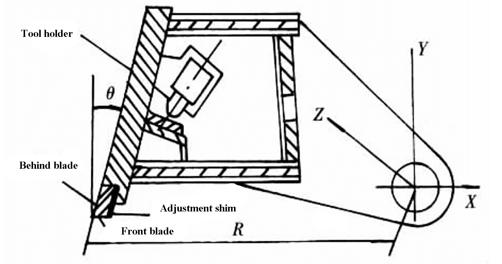
Fig. 3 Blade structure schematic diagram in hydraulic rotary shear
The calculation of shear force in swing-type plate shears is typically done using the tool carrier to achieve linear motion in the formula for oblique blade shearing.
While theoretically possible, the actual machining process involves simplifying the blade mounting surface from a spatial spiral surface to a plane. This results in changes to the shear clearance and shear rear angle during the shearing process.
Changes to the shear clearance can affect the shear force and decrease the quality of the shearing process. On the other hand, changes to the rear angle after shearing can cause wear and even extrusion between the blade and the plate, ultimately increasing the shear force.
Currently, the simplified process is commonly used in manufacturing the blade mounting surface of swing-type plate shears. Therefore, it is essential to consider the influence of shear clearance and the change in rear angle when calculating the shear force.

As the founder of MachineMFG, I have dedicated over a decade of my career to the metalworking industry. My extensive experience has allowed me to become an expert in the fields of sheet metal fabrication, machining, mechanical engineering, and machine tools for metals. I am constantly thinking, reading, and writing about these subjects, constantly striving to stay at the forefront of my field. Let my knowledge and expertise be an asset to your business.