Long Shaft Machining: Minimizing Bending Deformation
Ever wondered why long, slender shafts bend during machining? This article reveals the hidden forces at play and offers practical solutions to enhance precision. Learn how to minimize deformation and improve your machining techniques for optimal results.
During the machining process, many shaft-like parts have a length-to-diameter ratio (L/d) greater than 25.
Under the combined effects of cutting forces, gravity, and tip-clamping forces, a horizontally oriented, long and thin shaft is prone to bending or even instability.
Therefore, when turning such shafts, it is necessary to improve their stress distribution.
Machining method: Reverse-feed turning is employed along with a series of effective measures such as selecting appropriate tool geometry, cutting parameters, clamping devices, and using a steady rest to support the shaft.
1. Analysis of factors causing bending deformation during turning of long and thin shafts
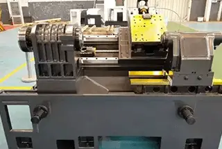
There are two main traditional clamping methods for turning long and thin shafts on a lathe: one is using one tip and one center, and the other is using two tips.
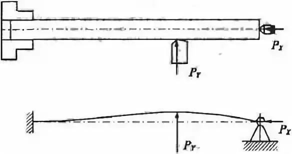
Here, we mainly analyze the one-tip-and-one-center clamping method, as shown in Figure 1.
Figure 1. One-tip-and-one-center clamping method and force analysis.
Through practical machining analysis, the main reasons for the bending deformation of long and thin shafts during turning are:
(1) Deformation caused by cutting forces
During the turning process, the cutting forces generated can be decomposed into axial cutting force PX, radial cutting force PY, and tangential cutting force PZ. Different cutting forces have different effects on the bending deformation of long and thin shafts during turning.
1)Effect of radial cutting force PY
Radial cutting force is applied perpendicular to the plane passing through the axis of the long and thin shaft. Due to the poor rigidity of the long and thin shaft, the radial force will bend the shaft, causing it to deform in the horizontal plane. The effect of radial cutting force on the bending deformation of the long and thin shaft is shown in Figure 1.
2)Effect of axial cutting force PX
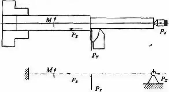
Axial cutting force is applied parallel to the axis of the long and thin shaft, creating a bending moment on the workpiece. For general turning processes, the effect of axial cutting force on the bending deformation of the workpiece is not significant and can be ignored. However, due to the poor rigidity and stability of the long and thin shaft, when the axial cutting force exceeds a certain value, the shaft will bend longitudinally and cause deformation. This is shown in Figure 2.
(2) Effect of cutting heat
The cutting heat generated during machining can cause thermal deformation and elongation of the workpiece. During turning, the chuck and tailstock center are fixed and the distance between them remains constant.
As a result, the axial elongation of the long and thin shaft is limited by the fixed distance, leading to axial compression and bending deformation of the shaft when it undergoes thermal expansion.
Therefore, improving the machining precision of long and thin shafts is essentially a matter of controlling the forces and thermal deformation in the process.
2. Measures to improve machining accuracy of long and thin shafts
To improve the machining accuracy of long and thin shafts, different measures should be taken according to different production conditions.
(1) Choosing the appropriate clamping method
Of the two traditional clamping methods used for turning long and thin shafts on a lathe, using a double-center-point clamping method ensures accurate workpiece positioning and coaxiality.
However, this method is not suitable for long and thin shafts with poor rigidity, high bending deformation, and vibration, and is only suitable for workpieces with low length-to-diameter ratios, small machining allowances, and high coaxiality requirements.
For machining long and thin shafts, a one-tip-and-one-center clamping method is commonly used.
However, if the tailstock center is tightened too much, it may not only bend the long and thin shaft but also hinder its thermal elongation during turning, causing axial compression and bending deformation.
In addition, the chuck clamping surface and the center hole of the tailstock may not be coaxial, causing over-positioning after clamping and resulting in bending deformation of the long and thin shaft.
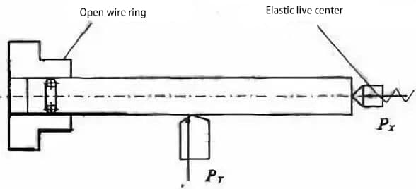
Therefore, when using the one-tip-and-one-center clamping method, an elastic top should be used to allow the long and thin shaft to elongate freely due to thermal expansion, reducing thermal bending deformation.
At the same time, an open wire ring can be inserted between the chuck and the long and thin shaft to reduce the axial contact length between them, eliminate over-positioning during installation, and reduce bending deformation, as shown in Figure 3.
(2) Directly reducing stress deformation of long and thin shafts
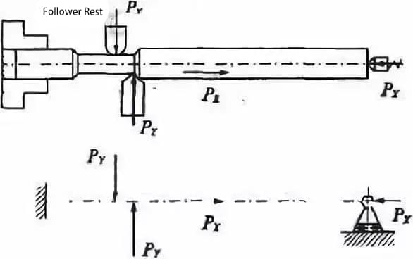
1)Using a steady rest and center rest
When turning long and thin shafts using a one-tip-and-one-center clamping method, to reduce the influence of radial cutting force on bending deformation, a steady rest and center rest are traditionally used.
This adds support to the long and thin shaft, increasing its stiffness and effectively reducing the impact of radial cutting force.
2)Using axial clamping method to turn long and thin shafts
While using a steady rest and center rest can increase the stiffness of the workpiece and eliminate the impact of radial cutting force, it cannot solve the problem of axial cutting force bending the workpiece, especially for long and thin shafts with large length-to-diameter ratios, where bending deformation is more obvious.
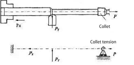
Therefore, an axial clamping method can be used to turn long and thin shafts. Axial clamping turning refers to a process in which one end of the long and thin shaft is clamped by a chuck, and the other end is clamped by a specially designed collet chuck that applies axial tension to the shaft, as shown in Figure 4.
During the turning process, the long and thin shaft is constantly subjected to axial tension, which solves the problem of axial cutting force bending the workpiece.
Under the action of axial tension, the degree of bending deformation caused by radial cutting force is reduced, and the axial elongation caused by cutting heat is compensated, improving the stiffness and machining accuracy of the long and thin shaft.
3)Using reverse cutting method to turn long and thin shafts
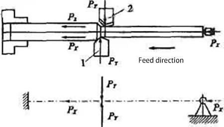
Reverse cutting method refers to a process in which the cutting tool feeds towards the tailstock direction from the spindle chuck during the turning process of the long and thin shaft, as shown in Figure 5.
This way, the axial cutting force generated during the machining process makes the long and thin shaft under tension, eliminating the bending deformation caused by axial cutting force.
At the same time, using an elastic tailstock center can effectively compensate for the compression deformation and thermal elongation of the workpiece from the cutting tool to the tailstock end, avoiding bending deformation of the workpiece.
Using a dual-tool approach to turn long and thin shafts on a modified lathe bed with an added rear tool post, both the front and rear cutting tools can be used simultaneously, as shown in Figure 6.
Two turning tools are positioned radially opposite each other, with the front tool installed in the correct orientation and the rear tool installed in reverse.
The radial cutting forces generated during turning with the two tools cancel each other out, resulting in minimal workpiece deformation and vibration and high machining accuracy, making it suitable for batch production.
4)Magnetic cutting is used for turning slender shafts.
The principle of magnetic cutting is similar to that of reverse cutting. During turning, the slender shaft is stretched by magnetic force, reducing its bending deformation and improving its machining accuracy.
(3) Control the cutting amount reasonably.
The selection of cutting amount has an impact on the size of cutting forces and the amount of cutting heat generated during the cutting process. Therefore, it also affects the deformation caused when turning slender shafts.
1)Cutting depth (t)
Assuming the stiffness of the machining system is determined, as the cutting depth increases, the cutting forces and the amount of cutting heat generated during turning also increase. This leads to an increase in the deformation caused by the forces and heat applied to the slender shaft.
Therefore, when turning slender shafts, it is recommended to minimize the cutting depth as much as possible.
2)Feed rate (f)
Increasing the feed rate will increase the cutting thickness and cutting forces, but the increase in cutting forces is not directly proportional to the increase in feed rate.
Thus, the deformation coefficient caused by the forces applied to the slender shaft will decrease. From the perspective of improving cutting efficiency, increasing the feed rate is more beneficial than increasing the cutting depth.
3)Cutting speed (v)
Increasing the cutting speed helps to reduce the cutting forces. This is because as the cutting speed increases, the cutting temperature rises, the frictional force between the tool and workpiece decreases, and the deformation caused by forces applied to the slender shaft is reduced.
However, excessive cutting speed may cause the slender shaft to bend due to centrifugal forces, which can disrupt the smoothness of the cutting process.
Therefore, the cutting speed should be controlled within a certain range, and for workpieces with a large length-to-diameter ratio, the cutting speed should be appropriately reduced.
To reduce the bending deformation of slender shafts during turning, it is important to minimize the cutting forces generated during turning.
Among the geometric angles of the tool, the rake angle, principal inclination angle, and inclination angle have the greatest influence on cutting forces.
1)Rake angle (γ)
The rake angle (γ) directly affects cutting forces, cutting temperature, and cutting power.
Increasing the rake angle can reduce the plastic deformation of the metal layer being cut, resulting in a significant reduction in cutting forces.
Therefore, when turning slender shafts, it is recommended to increase the rake angle of the tool as much as possible, within the constraint of ensuring that the tool has sufficient strength. The rake angle is generally taken as γ=13°-17°.
2)Principal inclination angle (kr)
The principal inclination angle (kr) affects the size and proportion of the three cutting forces. As the principal inclination angle increases, the radial cutting force decreases significantly, while the tangential cutting force increases between 60°-90°.
The proportion of the three cutting forces is most reasonable in the range of 60°-75°. When turning slender shafts, a principal inclination angle greater than 60° is generally used.
3)Inclination angle (λs)
The inclination angle (λs) affects the flow direction of chips during turning, the strength of the tool tip, and the proportion of the three cutting forces.
As the inclination angle increases, the radial cutting force decreases significantly, but the axial and tangential cutting forces increase.
The proportion of the three cutting forces is most reasonable within the range of -10° to +10°. When turning slender shafts, a positive inclination angle of 0° to +10° is commonly used to make the chips flow towards the surface to be machined.
3. Conclusion:
Due to the poor rigidity of slender shafts, large deformation caused by forces and heat during turning makes it difficult to ensure the machining quality requirements of slender shafts.
However, by using appropriate clamping methods and advanced machining methods, selecting reasonable tool angles and cutting amounts, and other measures, the machining quality requirements of slender shafts can be guaranteed.
As the founder of MachineMFG, I have dedicated over a decade of my career to the metalworking industry. My extensive experience has allowed me to become an expert in the fields of sheet metal fabrication, machining, mechanical engineering, and machine tools for metals. I am constantly thinking, reading, and writing about these subjects, constantly striving to stay at the forefront of my field. Let my knowledge and expertise be an asset to your business.
Why do CNC machine tools sometimes fail to deliver precise results? From tool wear to improper machine calibration, various factors can impact accuracy. This article dives into nine common issues…
Ever wondered what powers the precision and efficiency of modern manufacturing? In this article, we explore the top CNC milling machine manufacturers, highlighting their innovations and contributions. You'll learn about…
Have you ever wondered which companies lead the milling machine industry? This article unveils the top 10 milling machine manufacturers of 2024, highlighting their innovations, global impact, and contributions to…
How does modern manufacturing achieve nearly perfect precision? Ultra-precision machining techniques enable astonishing accuracy, reaching sub-micron and nanometer levels. This article explores methods like ultra-precision cutting, grinding, lapping, and special…
Have you ever wondered how complex metal parts are precisely crafted? CNC machining is the answer. This article explains how computer-controlled tools shape materials like metal into intricate components with…
Are you in the market for a lathe machine but overwhelmed by the options? In this blog post, we'll explore the key factors to consider when choosing a lathe manufacturer.…
Imagine having the perfect tool for every unique challenge in mold making. From intricate free-form surfaces to high-precision requirements, selecting the right cutting tools for CNC milling can dramatically influence…
Ever wondered why your CNC milling machine vibrates and ruins your precision? This article explores twelve expert tips to minimize cutting vibrations, from using sharp inserts to optimizing cutting parameters.…
What makes hobs so crucial in gear manufacturing? This article explores nine different types of hobs, detailing their unique features and applications in machining. From gear hobs to specialized tooth…