01
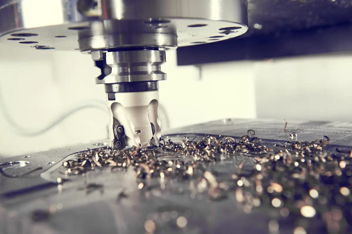
Sharp inserts can be used to decrease the cutting force of CNC milling machines.
Clamped inserts come in coated and uncoated varieties. Uncoated inserts are typically sharper than coated inserts because if the inserts are to be coated, the edges must be passivated (ER-treated) first.
This is because a sharp edge can weaken the bond strength of the coating at the edge.
02
When cutting to a specific depth, using a small tip radius can significantly reduce cutting forces, particularly radial forces.
The radial cutting force is the primary cause of vibrations in slender rod tools or workpieces.
Regardless of whether it’s bumping or milling, the larger the radius of the tip arc, the greater the tendency for slender shanks to vibrate at the same cutting depth.
03
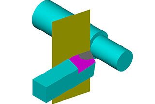
When selecting the depth of cut, it should be avoided that the depth of cut is equal to the arc radius of the tool tip.
04
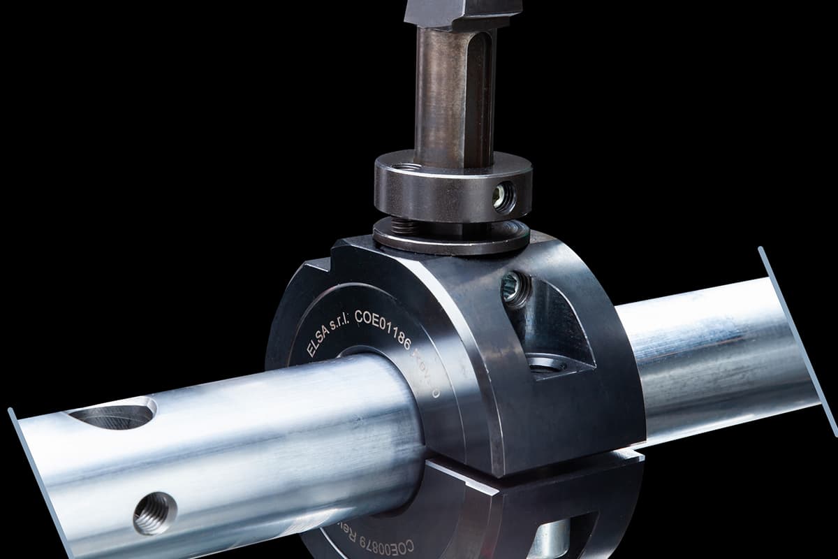
For key cutting of slender knife shanks or external turning of slender shafts, using a tool with a 90° primary tilt is beneficial in reducing vibrations.
Whether it’s an external turning tool turning a slender shaft or a keyhole in a slender tool holder, a 90° tool with the main offset angle generates the lowest radial cutting force while producing the highest axial force at the blade edge.
05
For milling cutters with slender rods, round insert cutters are most effective in reducing vibrations.
Milling cutters are the opposite of agitating cutters.
The closer the main tilt angle is to 90°, the greater the radial cutting force and the more the shank will vibrate.
06
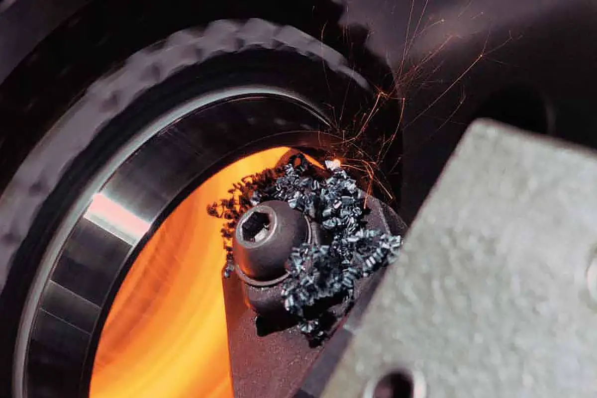
When CNC milling machines use slender rod end mills to mill deep cavities, plunge milling is often employed. Insertion milling refers to the axial feeding of a tool similar to a drill when milling deep cavities.
For a long bar with an overhang greater than 3 times its diameter, it is recommended to use axial feed insertion milling.
However, the end mill insert has a radial cutting edge of a certain width.
The tool supplier has technical data that indicates the maximum width of the tool when using insertion milling.
07
In milling thin-walled workpieces, the cause of vibrations is solely from the workpiece, also known as a box or bowl part.
Since the vibration originates from the workpiece itself, the primary focus when handling the milling of such parts is to enhance the clamping of the workpiece.
08
When boring inner holes, the smaller the blade edge angle, the better.
This is because the secondary tilt becomes very large, reducing the chatter contact area between the secondary cutting edge and the surface being machined, making it harder for chatter to turn into vibration.
Additionally, the likelihood of the secondary cutting edge compressing a chip is also low.
09
If a face milling cutter employs a sparse-toothed unequal pitch milling cutter, milling vibrations can be reduced.
The term “tooth” refers to the blade.
For instance, a 100mm diameter face mill with a 5-blade cutter must generate 50% less milling force compared to a 10-blade cutter if they both cut all three elements equally.
10
Employ front and large rear corners of the blade with a light-hearted chip breaker slot.
Such inserts have the smallest cutting wedge angle during filing or milling, resulting in lighter and faster cutting.
11
Fine-tune the cutting parameters, which can be effective only if the cutting vibration is not severe.
The general adjustment method involves reducing the tool or workpiece rotation speed, decreasing the depth of cut, and increasing the tool’s feed per revolution or abusive tooth travel.
In case of vibration during the internal thread turning, the feed step to finish the thread turning can be reduced by 1 or 2 cuts.
12
Rationalize the process path of the blade. Proper routing of the process is very important for milling operations.
There is a distinction between straight and reverse milling, and traditional milling theory suggests that reverse milling reduces milling vibration. However, this is only effective in suppressing vibrations generated by screw clearance.
With most modern milling machines fitted with ball or roller screws, reverse milling’s damping effect is minimal.
Whether it’s down milling or up milling, as long as the direction of the milling force is consistent with the clamping direction of the workpiece, it can help eliminate vibrations in bent plate parts.